
First, this is my first official DIY. I was planning on doing a few others, but i accidentally deleted the pictures of my fuse block relocate and custom a/c condenser stuff.
Ok, lets get started. This project took me an afternoon. It is not that difficult, just time consuming. Total cost about $35. What we are doing is adding LED lights on top of the printed circuit board.
Materials:
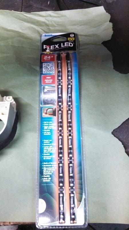
-LED Strip, Autozone part number 060071 or 77422b, 24" red flexible LED
-roll of 24 gauge speaker wire or equivalent
-Light duty solder gun or pencil, suggest 25 or 35 watt
-Flux (Radio Shack)
-Solder
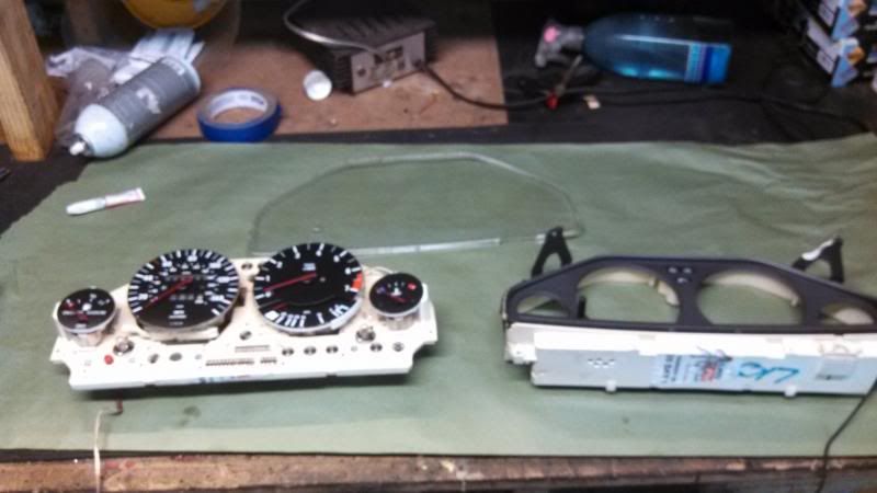
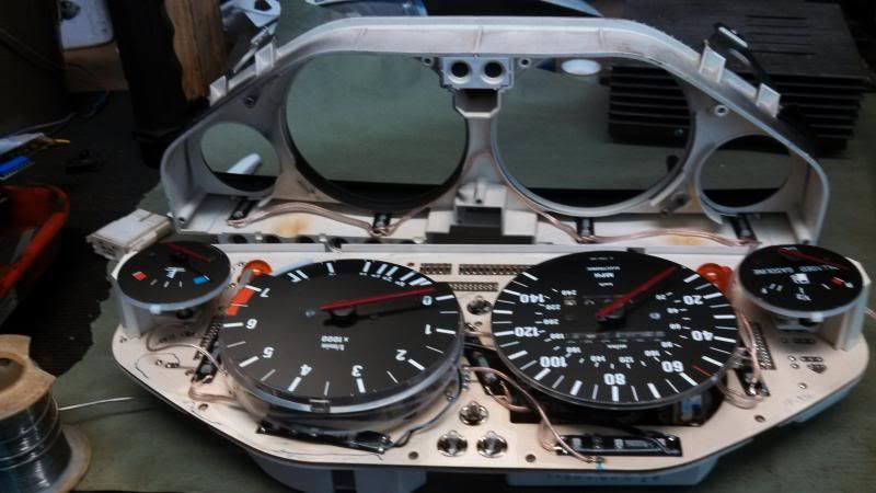
1. First remove the cluster and disassemble. You do not have to remove the clear cover. I had to re-glue mine.
2. Remove the LED strip and prepare to cut it into pieces. There are specific places that you need to cut it. The package comes in 2 12" pieces.
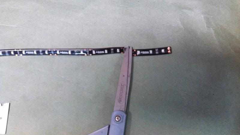
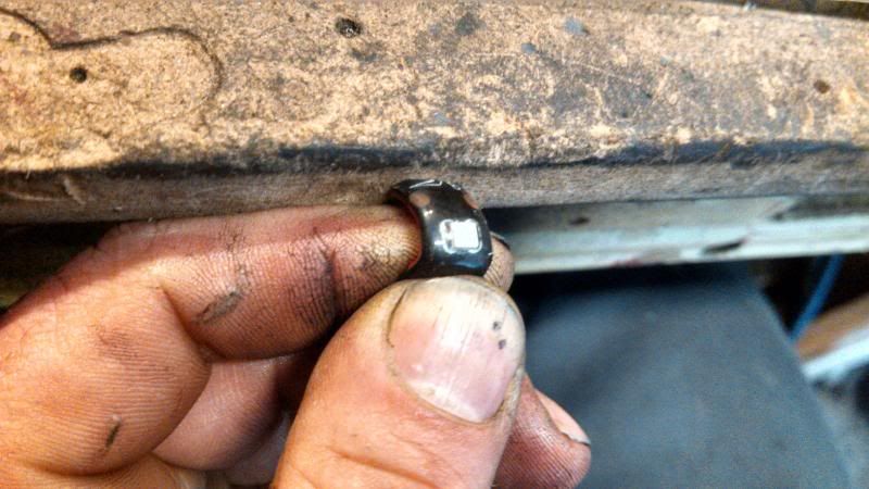
3. You need to cut it in specific places. You must be between the copper circles so you can attach the wires to link then together. I tried to experiment with them and i can tell you 100% that you must keep the entire section with all 3 LED's together to get them to work. If you do not need to link the rear of the set, than you can cut it just passed the last diode.
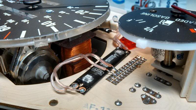
4.This is what you need to get it to look like to solder the wires to the strip.
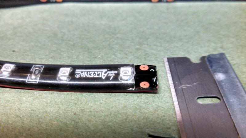
I found the easiest way to do this is to bend the strip and put pressure on the outer rubber layer and slowly slice with a new razor blade. When it gets low, you can just tear the layer of rubber off with your fingernail.
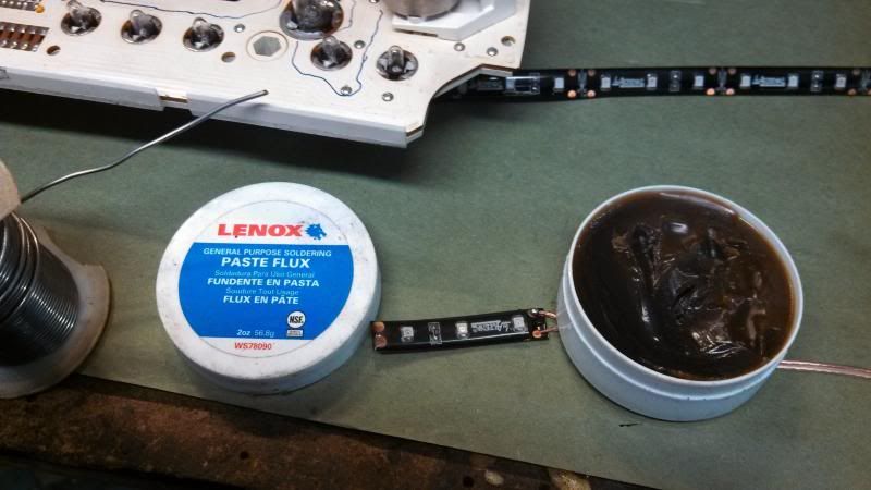
5.Now, I am not an electrical engineer, but I consider myself good around electricity. I dont really ever use flux, but i didnt want to ruin the LED by over heating the strip. Flux with enable the solder to join alot easier, thus cutting down on the heating time. This is the way that i do it. As someone pointed out below, this is not the number one choice for flux. It can cause corrosion problems over time. A lot of people have no problems after years of using this. Use at you own risk. You can get better flux at Radio Shack Or use good rosin core solder. I used rosin core, but liked using flux more. You can decide for your self after doing research.
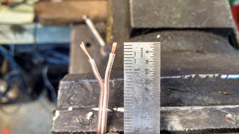
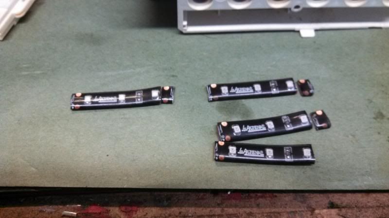
5a. Strip the wire, not too much. The pic below shows 2 wires. the one on the right is what I prefer for a single connection. The example on the left is what i would prefer for a double connection and placing this one on the bottom, or underneath the second wire. If they are left too long, they will have a better chance shorting when closing the case.
5b. Once stripped properly, i dip the wire in the flux.
5c. Touch the soldering iron/pencil to the solder.
5d. Touch the wire to the soldering pencil, tinning the copper strands.
5e. Touch the pencil to the solder again
5f. Touch the wire to the flux again and place it on the copper spot on the LED strip.
5g. Finally you can touch the pencil to the wire and circle. they should join easily.
I blow on the joint then check for strength. Things to keep in mind are to not over heat it. Better to try more flux and a few light dabs with the pencil, than to just hold the pencil until it all melts.
6.Lay out the LED where you would like them. You must pay attention to screw holes and bulb surrounds. You will be really sorry if you mess that up.
Things to keep in mind regarding this step. You must pay attention and make sure the polarity is right. LED's only operate with one direction of flow. If you get it backwards, no big deal just switch the wires. No harm done. Also the electricity must flow in the direction of the words. It will not run backwards Take your time and get the wire cut to the exact length you want it. there is not a lot of room in there.
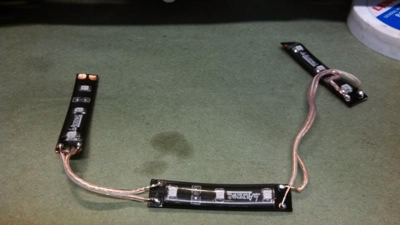
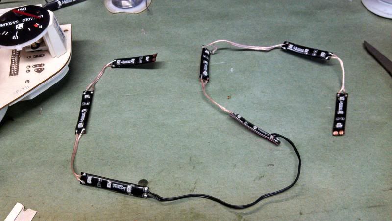
7. This is what i made for the circuit board. 7 LED sets wired in series. I suggest checking your work as you go. i used an external 12v power source, but i think you can use any battery from 9v rectangle battery to a cordless drill battery.
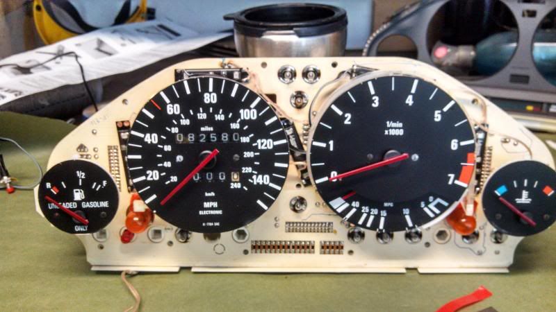
8. Here is where I placed them. 2 are hidden in the pic. They are on the bottom edge of the speedo and tach.
9. This is where you hook up the power and ground for the LED's. Its the factory dash wiring for lighting. The ground is the terminal number 24 on the C2. On the plug, it is a brown/black wire. It will be the 3rd one down the row, on the inside. The power hook up is pin 23 grey/red on the plug, and the next one down obviously.
10. Ok now we are done with that. This will be sufficient for the most part but i eliminated the amber fiber optic "flood lights" as well. I have mixed thoughts about the following steps. I am not sure it is needed. Maybe try out what we already did before you proceed with the last steps.
It looks great when it is turned down on the dimmer all the way, but then the rest on the Dash is a little too dim. I didnt have any spray tint here at the house or at Autozone. I think that will take care of it and make it even better.
Ok, on with the show. Cut 4 strips as short as possible. Place them centered on the window for the flood light.
11. I dont have a pic of the mock up of the last 4 strips, but i built them out of the surround and then placed them on the surround when I was done soldering them. I then ran a pigtail off the the top on the first LED and piggy backed off of that connection.
12. No picture of this step, but it is a precaution. I hot glued the wires to the board and surround. I also glued around the solder joint to prevent cracking down the road and to insulate to prevent shorts. You would be surprised how handy a hot glue gun can be.
12. Seal up the cluster. If you have the lens off, than i suggest to leave it off so you can tint the 4 flood lights to be more easy on the eyes.
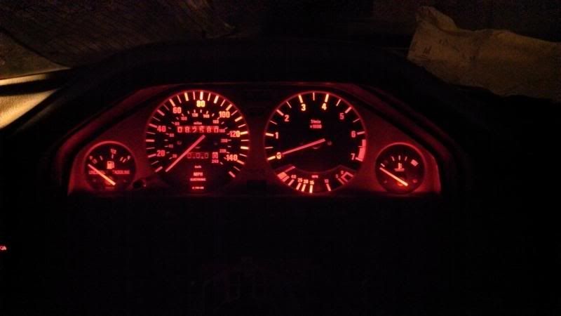
I scraped the paint off my needles because i didnt like it at night. the following pic is at full blast dimmer, the latter is turned down all the way.
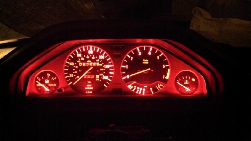
So in hindsight, I would do the 4 in the front, but tint them with spray tint. Painted needles sucks. LED's are the Shit. Obviously, i hold no responsibility of how you melt your car or catch it on fire. I performed this on a 87 325es
Ok, lets get started. This project took me an afternoon. It is not that difficult, just time consuming. Total cost about $35. What we are doing is adding LED lights on top of the printed circuit board.
Materials:
-LED Strip, Autozone part number 060071 or 77422b, 24" red flexible LED
-roll of 24 gauge speaker wire or equivalent
-Light duty solder gun or pencil, suggest 25 or 35 watt
-Flux (Radio Shack)
-Solder
1. First remove the cluster and disassemble. You do not have to remove the clear cover. I had to re-glue mine.
2. Remove the LED strip and prepare to cut it into pieces. There are specific places that you need to cut it. The package comes in 2 12" pieces.
3. You need to cut it in specific places. You must be between the copper circles so you can attach the wires to link then together. I tried to experiment with them and i can tell you 100% that you must keep the entire section with all 3 LED's together to get them to work. If you do not need to link the rear of the set, than you can cut it just passed the last diode.
4.This is what you need to get it to look like to solder the wires to the strip.
I found the easiest way to do this is to bend the strip and put pressure on the outer rubber layer and slowly slice with a new razor blade. When it gets low, you can just tear the layer of rubber off with your fingernail.
5.Now, I am not an electrical engineer, but I consider myself good around electricity. I dont really ever use flux, but i didnt want to ruin the LED by over heating the strip. Flux with enable the solder to join alot easier, thus cutting down on the heating time. This is the way that i do it. As someone pointed out below, this is not the number one choice for flux. It can cause corrosion problems over time. A lot of people have no problems after years of using this. Use at you own risk. You can get better flux at Radio Shack Or use good rosin core solder. I used rosin core, but liked using flux more. You can decide for your self after doing research.
5a. Strip the wire, not too much. The pic below shows 2 wires. the one on the right is what I prefer for a single connection. The example on the left is what i would prefer for a double connection and placing this one on the bottom, or underneath the second wire. If they are left too long, they will have a better chance shorting when closing the case.
5b. Once stripped properly, i dip the wire in the flux.
5c. Touch the soldering iron/pencil to the solder.
5d. Touch the wire to the soldering pencil, tinning the copper strands.
5e. Touch the pencil to the solder again
5f. Touch the wire to the flux again and place it on the copper spot on the LED strip.
5g. Finally you can touch the pencil to the wire and circle. they should join easily.
I blow on the joint then check for strength. Things to keep in mind are to not over heat it. Better to try more flux and a few light dabs with the pencil, than to just hold the pencil until it all melts.
6.Lay out the LED where you would like them. You must pay attention to screw holes and bulb surrounds. You will be really sorry if you mess that up.
Things to keep in mind regarding this step. You must pay attention and make sure the polarity is right. LED's only operate with one direction of flow. If you get it backwards, no big deal just switch the wires. No harm done. Also the electricity must flow in the direction of the words. It will not run backwards Take your time and get the wire cut to the exact length you want it. there is not a lot of room in there.
7. This is what i made for the circuit board. 7 LED sets wired in series. I suggest checking your work as you go. i used an external 12v power source, but i think you can use any battery from 9v rectangle battery to a cordless drill battery.
8. Here is where I placed them. 2 are hidden in the pic. They are on the bottom edge of the speedo and tach.
9. This is where you hook up the power and ground for the LED's. Its the factory dash wiring for lighting. The ground is the terminal number 24 on the C2. On the plug, it is a brown/black wire. It will be the 3rd one down the row, on the inside. The power hook up is pin 23 grey/red on the plug, and the next one down obviously.
10. Ok now we are done with that. This will be sufficient for the most part but i eliminated the amber fiber optic "flood lights" as well. I have mixed thoughts about the following steps. I am not sure it is needed. Maybe try out what we already did before you proceed with the last steps.
It looks great when it is turned down on the dimmer all the way, but then the rest on the Dash is a little too dim. I didnt have any spray tint here at the house or at Autozone. I think that will take care of it and make it even better.
Ok, on with the show. Cut 4 strips as short as possible. Place them centered on the window for the flood light.
11. I dont have a pic of the mock up of the last 4 strips, but i built them out of the surround and then placed them on the surround when I was done soldering them. I then ran a pigtail off the the top on the first LED and piggy backed off of that connection.
12. No picture of this step, but it is a precaution. I hot glued the wires to the board and surround. I also glued around the solder joint to prevent cracking down the road and to insulate to prevent shorts. You would be surprised how handy a hot glue gun can be.
12. Seal up the cluster. If you have the lens off, than i suggest to leave it off so you can tint the 4 flood lights to be more easy on the eyes.
I scraped the paint off my needles because i didnt like it at night. the following pic is at full blast dimmer, the latter is turned down all the way.
So in hindsight, I would do the 4 in the front, but tint them with spray tint. Painted needles sucks. LED's are the Shit. Obviously, i hold no responsibility of how you melt your car or catch it on fire. I performed this on a 87 325es


Comment