
I know we have some experts in here when it comes to precision machining and machine assembly, so hopefully one of you drops in here to set me straight.
Boring backstory:
I picked up a Delta 70-200 drill press on CraigsList last week. The unit had some significant surface rust from a life in a basement in the Santa Cruz Mountains, and there was enough spindle runout that I didn't need a dial indicator to detect it...BUT, it was nothing that a couple of weekends of TLC and some new bearings couldn't fix. This was a nice but not high-end machine when it was new in the mid/late 1990's, but it is still built better than anything new I can see on the market today for under about $2000. So, as with most of the larger machines in my workshop, I figured an older unit in need of some work would end up being the better buy versus some new China-made unit even with the used one being the same cost or a little more after refurb.
I tore the machine down to the very last screw to thoroughly clean and de-rust it, and I removed all the old bearings since they were nasty. I have new FAG bearings coming this week from Motion Industries. Proper installation of radial ball bearings is fairly straightforward, but the lower bearings between the spindle and quill are of what seems to be a sort of uncommon configuration. Basically everything I can find online for consumer-level drill presses like this shows upper and lower radial bearings, but none with a thrust bearing stacked in there like mine.
The questions:
A) First, what is the right order of operations here?
My assumption is to do it in this order:
1) Press 6206 onto spindle
2) Press tighter race of 2906 onto spindle
3) Drop ball cage and loose race of 2906 onto the spindle
4) Press the spindle+bearing assembly into the quill
5) Press the 6204 in to the top by both races, supporting the assembly by the bottom of the spindle
Step 4 leads to the second question, which I think is the really important one. Also, the spindle has threads which take a locknut above the 6204, which I guess ensures that there is no axial play in the inner races after final assembly.
B) How do I set the proper pre-load on the 2906 while pressing in the 6206? Also, how to keep good concentricity between the races of the 2906?
Screwing that part of the assembly process up seems like it would make the entire effort pointless since it would either ruin the bearings immediately, or lead to a very short, hot and noisy service life. The spindle+bearing assembly has to be pressed in by the outer race of the 6206 since the tighter press fit seemed to be between its OD and the quill based on what I observed during disassembly. But, pressing it in by the outer race also means it will be easy to overload the inner race against the 2906.
I am OK with paying a competent machine shop to do this for me since I only have basic tools for pressing bearings, but I feel like that will cost me more than the drill press did lol.
Bonus question: This design seems sort of overconstrained and wonky. Is this a common setup on any other mills or drill presses?
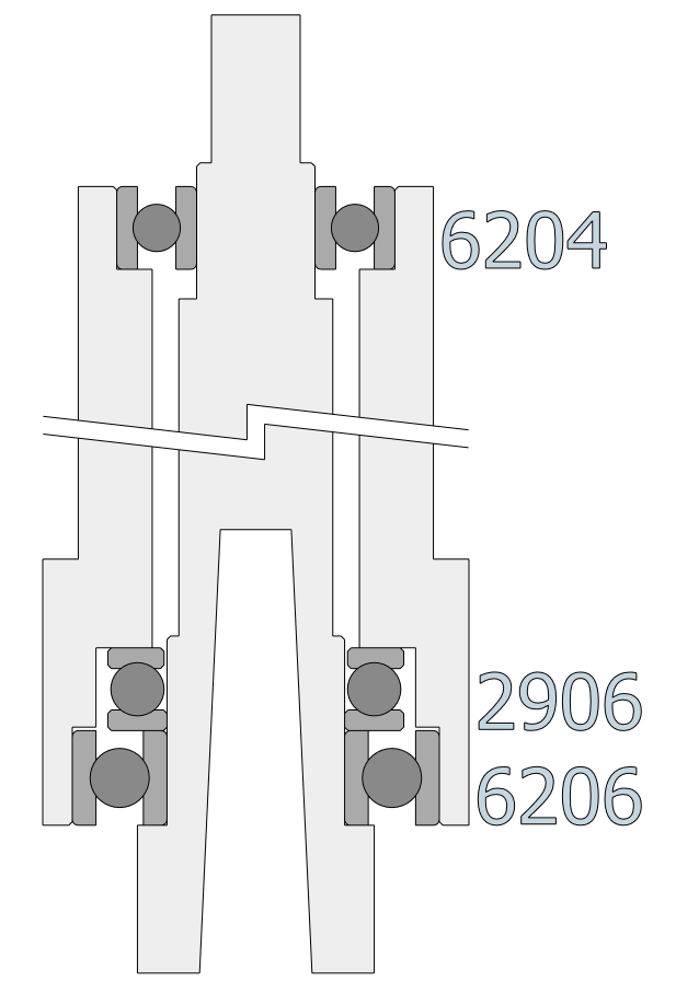
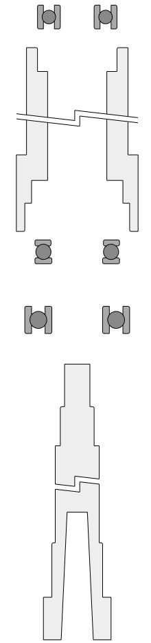
Here is a quick diagram of the assembly I am describing. Things are to-scale in the dimensions that count.
Boring backstory:
I picked up a Delta 70-200 drill press on CraigsList last week. The unit had some significant surface rust from a life in a basement in the Santa Cruz Mountains, and there was enough spindle runout that I didn't need a dial indicator to detect it...BUT, it was nothing that a couple of weekends of TLC and some new bearings couldn't fix. This was a nice but not high-end machine when it was new in the mid/late 1990's, but it is still built better than anything new I can see on the market today for under about $2000. So, as with most of the larger machines in my workshop, I figured an older unit in need of some work would end up being the better buy versus some new China-made unit even with the used one being the same cost or a little more after refurb.
I tore the machine down to the very last screw to thoroughly clean and de-rust it, and I removed all the old bearings since they were nasty. I have new FAG bearings coming this week from Motion Industries. Proper installation of radial ball bearings is fairly straightforward, but the lower bearings between the spindle and quill are of what seems to be a sort of uncommon configuration. Basically everything I can find online for consumer-level drill presses like this shows upper and lower radial bearings, but none with a thrust bearing stacked in there like mine.
The questions:
A) First, what is the right order of operations here?
My assumption is to do it in this order:
1) Press 6206 onto spindle
2) Press tighter race of 2906 onto spindle
3) Drop ball cage and loose race of 2906 onto the spindle
4) Press the spindle+bearing assembly into the quill
5) Press the 6204 in to the top by both races, supporting the assembly by the bottom of the spindle
Step 4 leads to the second question, which I think is the really important one. Also, the spindle has threads which take a locknut above the 6204, which I guess ensures that there is no axial play in the inner races after final assembly.
B) How do I set the proper pre-load on the 2906 while pressing in the 6206? Also, how to keep good concentricity between the races of the 2906?
Screwing that part of the assembly process up seems like it would make the entire effort pointless since it would either ruin the bearings immediately, or lead to a very short, hot and noisy service life. The spindle+bearing assembly has to be pressed in by the outer race of the 6206 since the tighter press fit seemed to be between its OD and the quill based on what I observed during disassembly. But, pressing it in by the outer race also means it will be easy to overload the inner race against the 2906.
I am OK with paying a competent machine shop to do this for me since I only have basic tools for pressing bearings, but I feel like that will cost me more than the drill press did lol.
Bonus question: This design seems sort of overconstrained and wonky. Is this a common setup on any other mills or drill presses?
Here is a quick diagram of the assembly I am describing. Things are to-scale in the dimensions that count.

Comment