
NOTE:
I no longer recommend the use of the Innovate LC-1/2 product. It's a long story, but I don't trust the accuracy or quality of the product anymore after using one for many years. It could just be my experience since MANY people run these and seem to be fine, so don't take my opinion as absolute truth.
OK, I finally condensed years of messing around with one of these wide band sensor setups into a few images. There is really ONE right way to install & configure this thing, and a large number of wrong ways (many of which I discovered over the years lol).
OK, so first you need to physically install the thing. The cable that comes with the Bosch LSU4.2 sensor is a bit short, and the best place I have found for the controller is under the battery tray with zip ties. I stuck them through the various screw holes & holes where the old O2 sensor connector clipped (it will either be cut-off or moved).
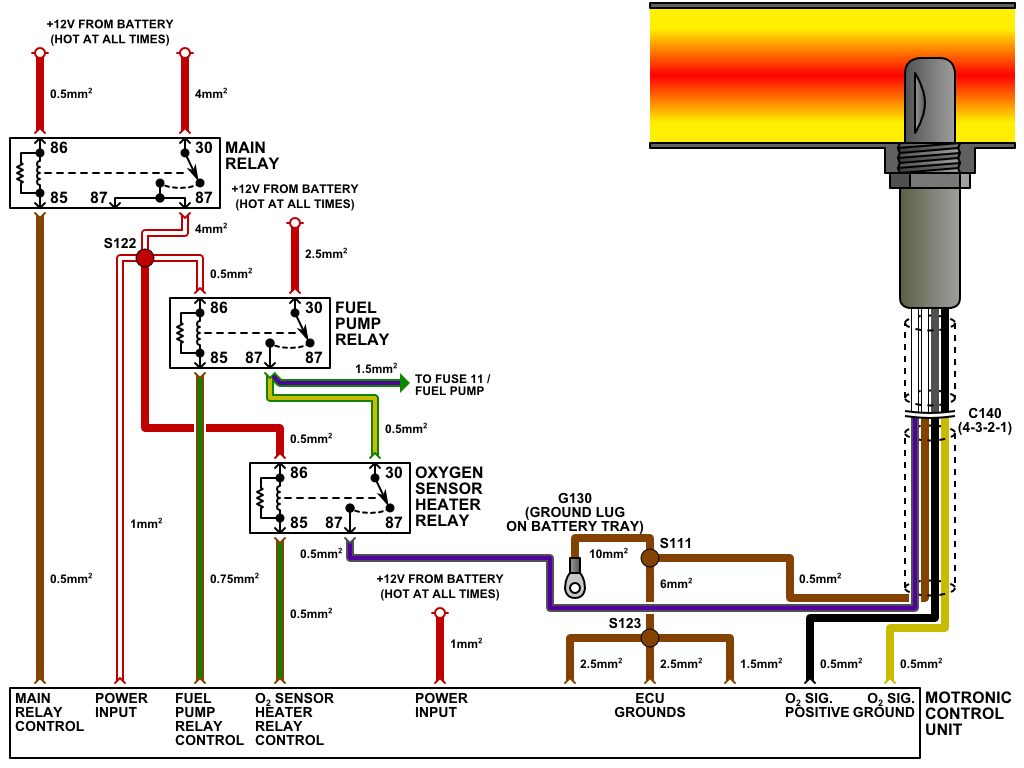
OK, so here is the stock wiring that is related to the O2 sensor in the 318iS.
To wire in the LC-1, you will have to do a fair amount of cutting & splicing. All of the needed connections are shown in the second diagram. I opted to run the LC-1 cable into the glove box, as well as the remnants of the stock O2 sensor harness. All connections were made with fully insulated spade connectors, and while you CAN use butt crimps, I would advise the use of something that you can easily service/disconnect.
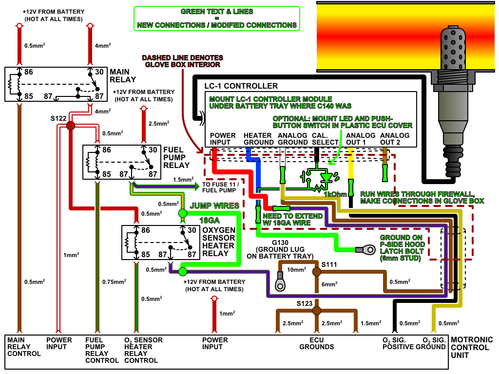
The installation of the LED and push-button is optional. I did it because I want to be able to re-calibrate the sensor easily and be able to see the device's status. I did this by getting a momentary push button, LED and resistor at Radio Shack, mounting them in some holes that I drilled in the plastic ECU cover in the glove box, and soldering them together.
Please note that the heater ground from the LC-1 is NOT, and SHOULD NOT be grounded by the ECU. I tried this originally and it caused a 100mV DC offset at the ground which really screwed things up. Buy a 1/4" ring terminal and run the heater ground to the hood latch bracket, or some other chassis ground if you prefer. Just don't use the lug where the ECU is grounded. The analog ground MUST be connected to both the stock O2 sensor ground AND the ECU's O2 signal ground lines. This is critical.
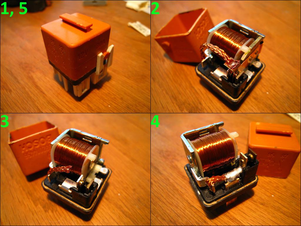
As far as jumping the O2 sensor relay goes, that is not optional either. The ECU cuts power to the O2 sensor under full throttle, which isn't good for the sensor, and a problem if you plan to actually USE it! The easy way to do it is to just jump the wires by cutting them and joining them with a butt splice or insulated spade connectors. There is a better way though. Bust open the relay and modify it! It's clean, and you won't get any check engine lights. I sealed the cover back on with some plain old super glue. If you are bad with a soldering iron, then just cut & splice the wires externally.
Anyway, with it all wired in you will need to calibrate it. I recommend doing this with the sensor not installed in the exhaust yet. If it is, you can unplug the fuel injectors, press the gas pedal all the way down and run the starter for 5-10 seconds to get fresh air into the system.
With it wired the way that it is, the LC-1 is not powered when the key is in the accessory position (and for good reason). Use a piece of wire to jump Fuse 10 to the slot for terminal 87 of the O2 sensor relay, put the car in accessory mode and run the calibration. When done, remove the wire & put the relay back. You do not want to do this with the car running because a) the sensor will be in exhaust gas, and b) the LC-1 stops its output when being programmed, which makes the ECU angry.
The last order of business is setting up the output. If you are using this with a stock ECU, you will need to make adjustments. The thing comes programmed as follows:
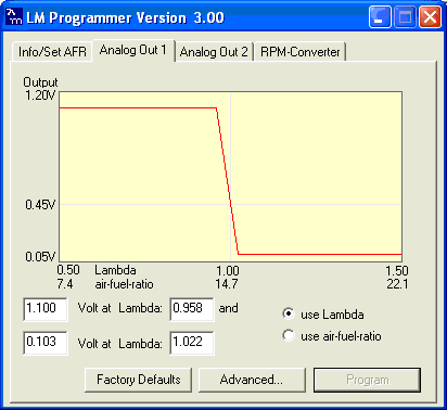
This won't work well with the Motronic. The Motronic expects a ~100mV - ~900mV input from the sensor, and will toss a CEL if it sees too high of a voltage. Set up the LC-1 so that it matches the shot below.

That's it. It is a lot of work to install one properly, I won't lie. There are tougher projects out there, but this one involves a very critical part of the engine controls and MUST be done properly. If it isn't, you will get bad mileage, reduced power and CELs.
I no longer recommend the use of the Innovate LC-1/2 product. It's a long story, but I don't trust the accuracy or quality of the product anymore after using one for many years. It could just be my experience since MANY people run these and seem to be fine, so don't take my opinion as absolute truth.
OK, I finally condensed years of messing around with one of these wide band sensor setups into a few images. There is really ONE right way to install & configure this thing, and a large number of wrong ways (many of which I discovered over the years lol).
OK, so first you need to physically install the thing. The cable that comes with the Bosch LSU4.2 sensor is a bit short, and the best place I have found for the controller is under the battery tray with zip ties. I stuck them through the various screw holes & holes where the old O2 sensor connector clipped (it will either be cut-off or moved).
OK, so here is the stock wiring that is related to the O2 sensor in the 318iS.
To wire in the LC-1, you will have to do a fair amount of cutting & splicing. All of the needed connections are shown in the second diagram. I opted to run the LC-1 cable into the glove box, as well as the remnants of the stock O2 sensor harness. All connections were made with fully insulated spade connectors, and while you CAN use butt crimps, I would advise the use of something that you can easily service/disconnect.
The installation of the LED and push-button is optional. I did it because I want to be able to re-calibrate the sensor easily and be able to see the device's status. I did this by getting a momentary push button, LED and resistor at Radio Shack, mounting them in some holes that I drilled in the plastic ECU cover in the glove box, and soldering them together.
Please note that the heater ground from the LC-1 is NOT, and SHOULD NOT be grounded by the ECU. I tried this originally and it caused a 100mV DC offset at the ground which really screwed things up. Buy a 1/4" ring terminal and run the heater ground to the hood latch bracket, or some other chassis ground if you prefer. Just don't use the lug where the ECU is grounded. The analog ground MUST be connected to both the stock O2 sensor ground AND the ECU's O2 signal ground lines. This is critical.
As far as jumping the O2 sensor relay goes, that is not optional either. The ECU cuts power to the O2 sensor under full throttle, which isn't good for the sensor, and a problem if you plan to actually USE it! The easy way to do it is to just jump the wires by cutting them and joining them with a butt splice or insulated spade connectors. There is a better way though. Bust open the relay and modify it! It's clean, and you won't get any check engine lights. I sealed the cover back on with some plain old super glue. If you are bad with a soldering iron, then just cut & splice the wires externally.
Anyway, with it all wired in you will need to calibrate it. I recommend doing this with the sensor not installed in the exhaust yet. If it is, you can unplug the fuel injectors, press the gas pedal all the way down and run the starter for 5-10 seconds to get fresh air into the system.
With it wired the way that it is, the LC-1 is not powered when the key is in the accessory position (and for good reason). Use a piece of wire to jump Fuse 10 to the slot for terminal 87 of the O2 sensor relay, put the car in accessory mode and run the calibration. When done, remove the wire & put the relay back. You do not want to do this with the car running because a) the sensor will be in exhaust gas, and b) the LC-1 stops its output when being programmed, which makes the ECU angry.
The last order of business is setting up the output. If you are using this with a stock ECU, you will need to make adjustments. The thing comes programmed as follows:
This won't work well with the Motronic. The Motronic expects a ~100mV - ~900mV input from the sensor, and will toss a CEL if it sees too high of a voltage. Set up the LC-1 so that it matches the shot below.
That's it. It is a lot of work to install one properly, I won't lie. There are tougher projects out there, but this one involves a very critical part of the engine controls and MUST be done properly. If it isn't, you will get bad mileage, reduced power and CELs.


Comment