These two sites aren't mentioned THAT much in this 24v forum. They should be, considering how useful they are.
Basic FAQ:
How difficult is the swap?
On a scale of 1-10, 1 being an oil change and 10 being rebuilding a transmission, I’d give this somewhere around a 5 or 6, depending on how you go about it.
How much will it cost?
This can and will vary greatly from person to person. It’s possible to do this swap for $500 or less, or you can spend upwards of $10,000. I’d say count on $2k for a basic m50 swap and $5k for a well done s52 swap. These are very rough estimates. It can be done much cheaper or at a much higher cost. It depends if you buy new or used parts, do the labor yourself, etc…
What are the major basic required parts?
Engine: m50, m52, s50, s52, complete with wire harness, ECU, accessories.
E34 525i oil pan, oil pump, dipstick
E36 engine mount arms
E28 motor mounts
E34 throttle cable
E21 brake booster
These are only the basics, and some may be substituted for other parts. People find cheaper/better parts to use all the time, but the above listed are the common parts that the majority of people use.
What needs fabricated/custom made/modified?
If you use an e30 325 transmission (Getrag 260), you’ll need to modify the transmission cross member and the shift linkage. Some welding experience is required for this, or you can purchase these parts from members of the r3vlimited.com forum who currently (as of 8/2009) produce them.
The e21 brake booster needs to have the shaft modified. It basically needs shortened, thinned down, and threaded. There are other ways to get the job done though.
Radiator hoses aren’t always a direct fit.
The wiring harness on the engine will need spliced into the body harness at the connector near the firewall.
How involved is the wiring?
It's important to understand what wiring is involved. There is the chassis and all of it's wiring, then your engine and all of it's wiring. There are many sensors and power/ground connections on the engine, and all of those wires are contained with an engine harness, which connects to the ECU and a connector at the firewall, which is where it interfaces with the chassis wiring. That connector (called C101 on e30's, called x20 on e36/e34 cars) is what needs modified, as the wiring is different.
There are about 15 wires that need connected. The best way to do this is look at the schematics and create a pin out chart. This process takes time and research, but isn’t physically hard to do. You don’t want to mess it up though, as you can heavily damage the wiring and components, or even start a fire. There are several companies that sell harness adaptors if you don’t want to mess with the wiring.
Most people get a spare body side plug from an e36/e34, as well as a spare engine side plug from an e30, and then splice these two parts together. This way, you aren’t hacking your cars harness or your engine harness.
__________________________________________________
How to read the wire diagrams:
Go here:
Find the manual for your car or engine, whatever side you are doing pinouts for.
Open the manual, and skip to the section that starts talking about power distribution and various under hood parts.
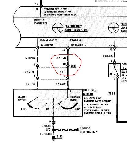
This is what it will look like:

You want to look for any instance of either c101 or x20, such as what is circled. C101 is the e30 engine connector, x20 is the e36/e34 connector. So if you are looking at an e30 manual, just look for c101. When you look at the e36/e34 manual, look for x20.
The c101 connector is the big round connector on your firewall. It has 20 or so pins on it (it’s a square connector with less pins if you have an 84-85 model). Each pin will be drawn out in this manual. Here, in the example, we are looking at pin 10 (see the 10 next to where it says c101).
The curved lines show which way the signal is coming through the connector. In this example, you see it’s coming FROM the oil level sensor, TO the engine oil fault indicator (the oil level light in your car).
The VI/GN and BU/WT are the colors of the wires. The wire between the sensor and the connector is blue with a white stripe, the wire between the connector and the warning light is Violet with a green stripe.
The .5 next to the color is the wire size. Apparently this is in millimeters squared. .5 will be a little wire, .75 medium, 1 is big. (I think).
You now know what color the wire is on the engine side, what color it is on the body side, what pin it is in the connector, and what its function is.
The schematics are generally laid out as power (+12 volts) from the top of the pages, to ground at the bottom of the pages. Further details of what various symbols mean can be found in the beginning pages of the manuals.
Basic FAQ:
How difficult is the swap?
On a scale of 1-10, 1 being an oil change and 10 being rebuilding a transmission, I’d give this somewhere around a 5 or 6, depending on how you go about it.
How much will it cost?
This can and will vary greatly from person to person. It’s possible to do this swap for $500 or less, or you can spend upwards of $10,000. I’d say count on $2k for a basic m50 swap and $5k for a well done s52 swap. These are very rough estimates. It can be done much cheaper or at a much higher cost. It depends if you buy new or used parts, do the labor yourself, etc…
What are the major basic required parts?
Engine: m50, m52, s50, s52, complete with wire harness, ECU, accessories.
E34 525i oil pan, oil pump, dipstick
E36 engine mount arms
E28 motor mounts
E34 throttle cable
E21 brake booster
These are only the basics, and some may be substituted for other parts. People find cheaper/better parts to use all the time, but the above listed are the common parts that the majority of people use.
What needs fabricated/custom made/modified?
If you use an e30 325 transmission (Getrag 260), you’ll need to modify the transmission cross member and the shift linkage. Some welding experience is required for this, or you can purchase these parts from members of the r3vlimited.com forum who currently (as of 8/2009) produce them.
The e21 brake booster needs to have the shaft modified. It basically needs shortened, thinned down, and threaded. There are other ways to get the job done though.
Radiator hoses aren’t always a direct fit.
The wiring harness on the engine will need spliced into the body harness at the connector near the firewall.
How involved is the wiring?
It's important to understand what wiring is involved. There is the chassis and all of it's wiring, then your engine and all of it's wiring. There are many sensors and power/ground connections on the engine, and all of those wires are contained with an engine harness, which connects to the ECU and a connector at the firewall, which is where it interfaces with the chassis wiring. That connector (called C101 on e30's, called x20 on e36/e34 cars) is what needs modified, as the wiring is different.
There are about 15 wires that need connected. The best way to do this is look at the schematics and create a pin out chart. This process takes time and research, but isn’t physically hard to do. You don’t want to mess it up though, as you can heavily damage the wiring and components, or even start a fire. There are several companies that sell harness adaptors if you don’t want to mess with the wiring.
Most people get a spare body side plug from an e36/e34, as well as a spare engine side plug from an e30, and then splice these two parts together. This way, you aren’t hacking your cars harness or your engine harness.
__________________________________________________
How to read the wire diagrams:
Go here:
Find the manual for your car or engine, whatever side you are doing pinouts for.
Open the manual, and skip to the section that starts talking about power distribution and various under hood parts.
This is what it will look like:

You want to look for any instance of either c101 or x20, such as what is circled. C101 is the e30 engine connector, x20 is the e36/e34 connector. So if you are looking at an e30 manual, just look for c101. When you look at the e36/e34 manual, look for x20.
The c101 connector is the big round connector on your firewall. It has 20 or so pins on it (it’s a square connector with less pins if you have an 84-85 model). Each pin will be drawn out in this manual. Here, in the example, we are looking at pin 10 (see the 10 next to where it says c101).
The curved lines show which way the signal is coming through the connector. In this example, you see it’s coming FROM the oil level sensor, TO the engine oil fault indicator (the oil level light in your car).
The VI/GN and BU/WT are the colors of the wires. The wire between the sensor and the connector is blue with a white stripe, the wire between the connector and the warning light is Violet with a green stripe.
The .5 next to the color is the wire size. Apparently this is in millimeters squared. .5 will be a little wire, .75 medium, 1 is big. (I think).
You now know what color the wire is on the engine side, what color it is on the body side, what pin it is in the connector, and what its function is.
The schematics are generally laid out as power (+12 volts) from the top of the pages, to ground at the bottom of the pages. Further details of what various symbols mean can be found in the beginning pages of the manuals.


Comment