

BK/Blue is high speed +12 and brn is ground yes.
And as for the temp switch, yes assuming you have a fan switch between them.
-
-
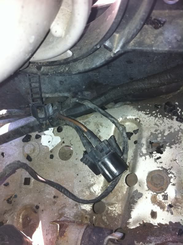
Is this the Stock fan wiring? It's three wires, brown, blue black, and black green..not sure what to do cause it's not what OP saidLeave a comment:
-
yeah, most decent aftermarket fans move more air and use less power. my flexalite S-blade fan uses 15 amps and moves 2000cfm. It's also far quieter.Leave a comment:
-
The stock fan will pull damn near 30 amps on high speed, esp when its old and dying :DLeave a comment:
-
wired up also...Got a fan from Jegs,doesnt pull alot of current,so was able to use stock wiring and fuses....knock on wood...been a year nowLeave a comment:
-
LOL - you know, I never even bothered to check to be honest. :roll:
*Edit - No I don't have it on....I figured I wouldn't have.Last edited by giantkeeper; 06-07-2011, 03:13 PM.Leave a comment:
-
Got it.
328ijunkie's directions for a single fan (pusher or puller)
herlsy's schematic for a dual fan system (for those who want/need it)Leave a comment:
-
If yours comes on when keyed then you have some other issues, your snowflake button on? You need to test and make sure the relays arent firing on "on" position
And i edited my original post with the picture from pelican parts
Unless youre talking about running dual fans (which isnt necessary in my optionin unless youre running a POS m42 radiator) the stock pusher is already relayed
its basically to either rewire the stock pusher, replace the stock pusher with another fan or put a puller in place of the pusher. This isnt to run dual fans. Dual fans arent necessary if youre using a real radiator.Leave a comment:
-
Sorry yeah i should re-edit it. It looked good in ms paint then photobucket screwed it.
The schematic is adding a puller fan, single speed, keeping the stock AUX fan. Either wired from the High Speed or Normal Speed relay circuits.
The box between 12v and the relay is the fuse. I put 30amp, but this could be decreased depending on how much power the fan draws.Leave a comment:
-
herlsy - couple of clarification questions.
1 - Is your schematic adding a second (puller) fan to the system, replacing the mechanical fan and keeping the current A/C pusher fan working as normal? Or is this to replace both mechanical and A/C pusher fans with one (puller) fan?
2 - what is in the box between the 12v and the relay? Isn't readable on my computer screen, even when I zoom in. I'm guessing 30 amp fuse?Leave a comment:
-
thank you, this always drove me nuts. it's so simple, and people make it really complicated.Leave a comment:
-
This might help some people that want to add a puller fan utilizing the stock circuit:

Leave a comment:
-
Perhaps this should be also moved (or copied?) to the FAQ section???
afterall, it does apply to more than just swaps.Leave a comment:

Leave a comment: