
In the home stretch of my restoration / swap project. Basically an E30 M3 with S50B32. Wouldn’t have been able to do it without the resources on this site. So I thought I might give something back or at least entertain a bit. :)
I know it is a lengthy post. Hey, I don’t post often but when I do… :popcorn:
I am not a composite expert or automotive engineer so keep that in mind. The following is self-taught. All of the composite materials can be easily purchased on line. I used Aircraft Spruce. Good selection and very knowledgeable staff. This could also be done similarly with fiberglass to keep costs down.
The goals:
1) make any mods bolt-on so I could go back to original anytime (S14 and dog-leg trans are in storage)
2) keep brake system / ABS OEM (didn’t want to drill the firewall, loose the booster)
3) keep OEM S50B32 trumpet length (happy with original tune / output)
4) keep an OEM look in the engine bay
5) play with composites
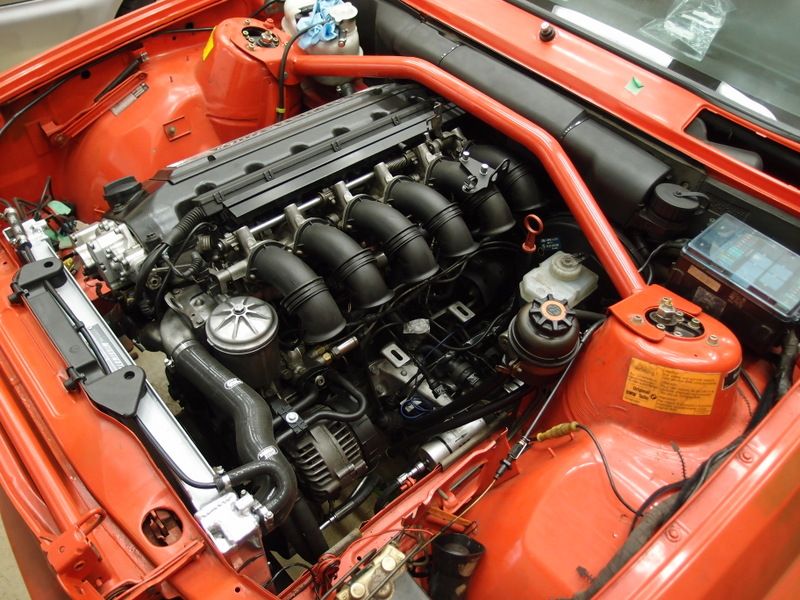
Obviously, the S50B32 plenum won’t fit with the OEM brake booster. However the trumpets do clear the booster with space for air flow. Better clearance is possible if the trumpet ends on the 5 and 6 cylinders are rotated forward a bit.

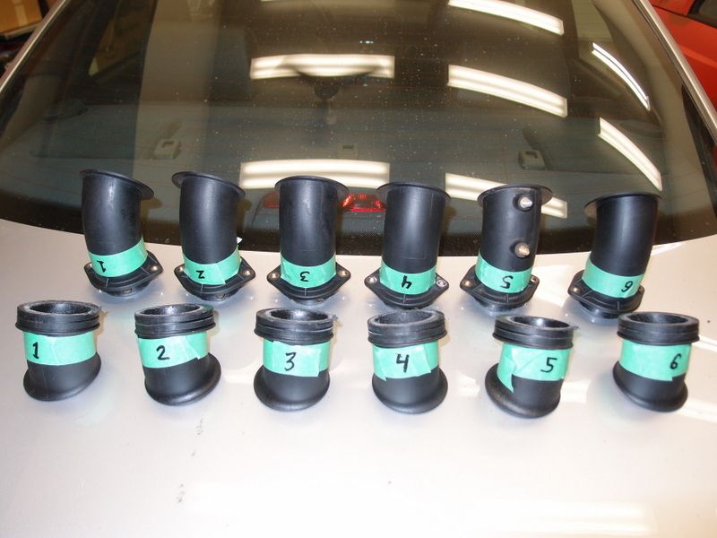
“Rotating” the trumpet ends involves cutting them at the mid section. All 6 were cut as this would be needed for the final assembly.
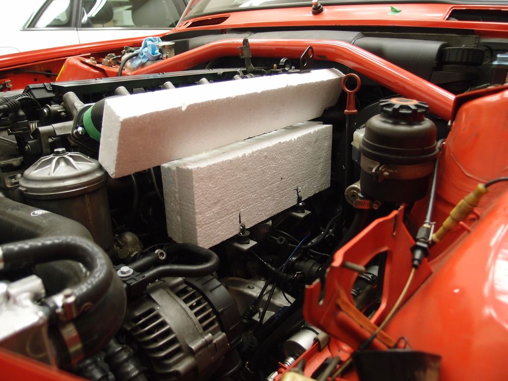
The most time consuming part was creating a 3D model of the intake. This would then be used to create a “negative” mold needed for the CF layup.
The model was made from Styrofoam, spray glue (3M), household plaster and latex paint.
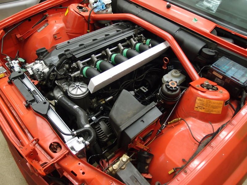
Using OEM plenum bracket with rubber mounts.
Needed to clear brake booster/fluid reservoir, PS reservoir, oil filter housing, dipstick, strut bar, and hood when closed as well as have air space around alternator for cooling. Also need to plan spots for the MAF connection, ICV, intake temp sensor, oil rebreather, oil return to pan (not all visible here).
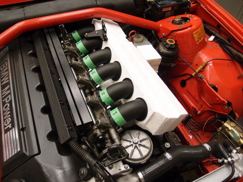
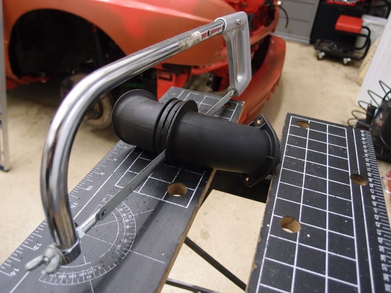
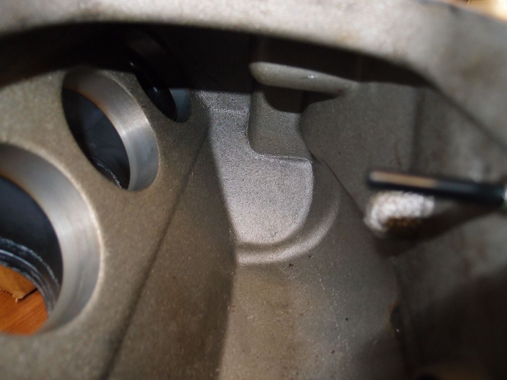
The volume of the intake is bigger than the original but the trumpets and opening to the MAF are basically unchanged. Not expecting any HP gains and hopefully no loss either. The inside space and distance of the trumpet openings to the inside walls are very close to the original. This is important to keep the air pressure waves as close to the OEM tuning as possible. It is hard to show with pictures. Here is the end of the trumpet opening and inside space of the OEM S50B32 plenum.
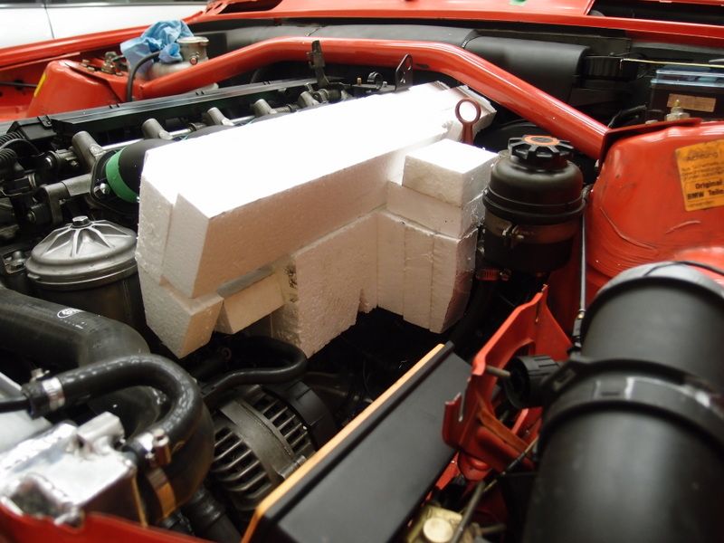
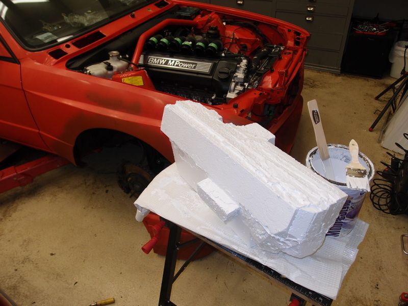
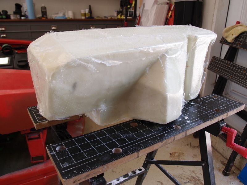
The styrafoam is painted with latex paint to make surface finishing easier. The styrafoam keeps showering snowflakes otherwise. Looks very crude now.
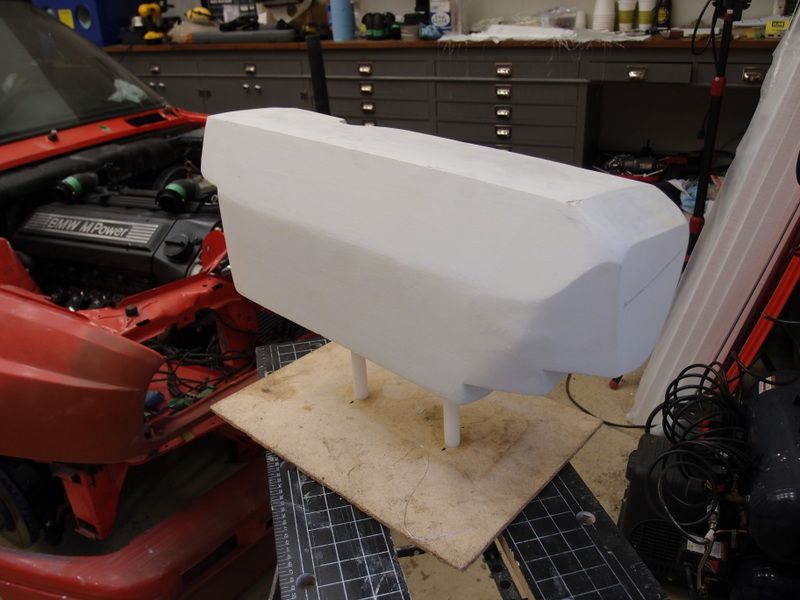
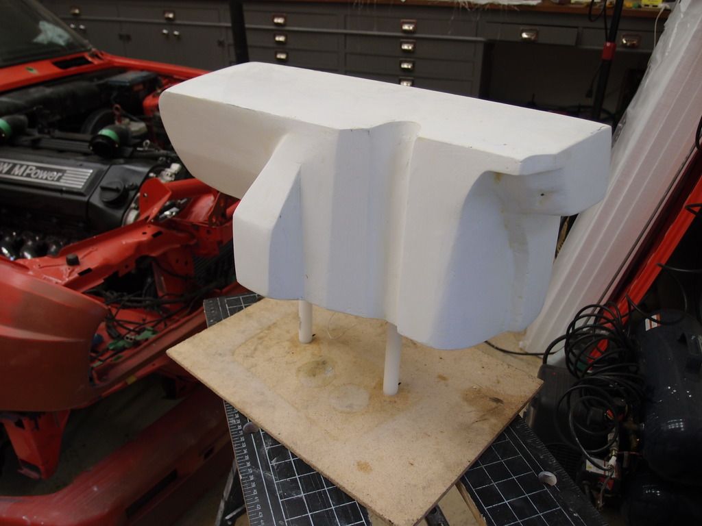
After several rounds of plaster, sanding, test fitting and one last coat of latex paint I ended up with this…
A mold release wax was applied in several coats to make sure the negative mold separated from the model. (http://www.aircraftspruce.ca/catalog...dRelease15.php)
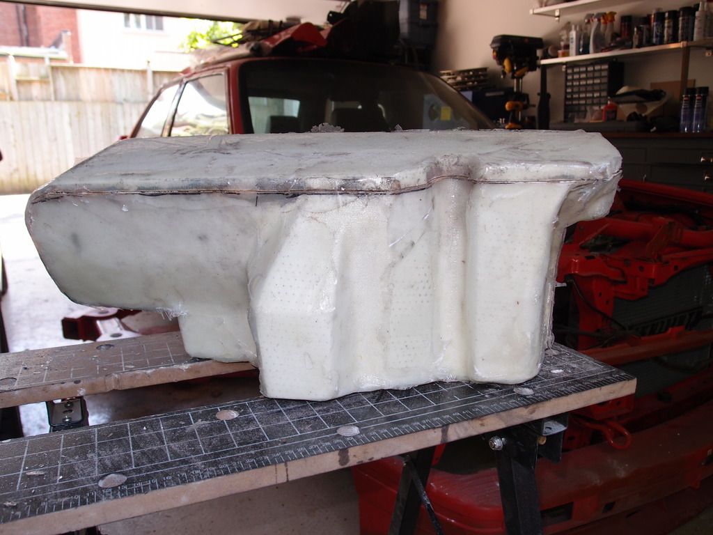
The negative mold was made out of fiberglass. Cheap and strong enough for this bit. Basically glass mat and resin. Sorry no pic of the in progress. Here is the cured product with the model still trapped inside.
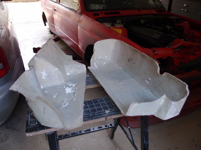
Given the tight curves in some sections the negative and model are actually locked together physically. One could make the mold in sections that separate to deal with this. Since this was a one-off project I used a destructive approach (parts of the model would be broken once the mold was done). A dremel is used to cut the fiberglass layer into two halves.
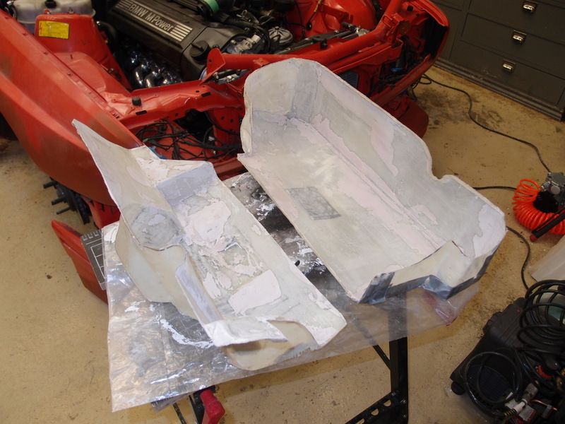
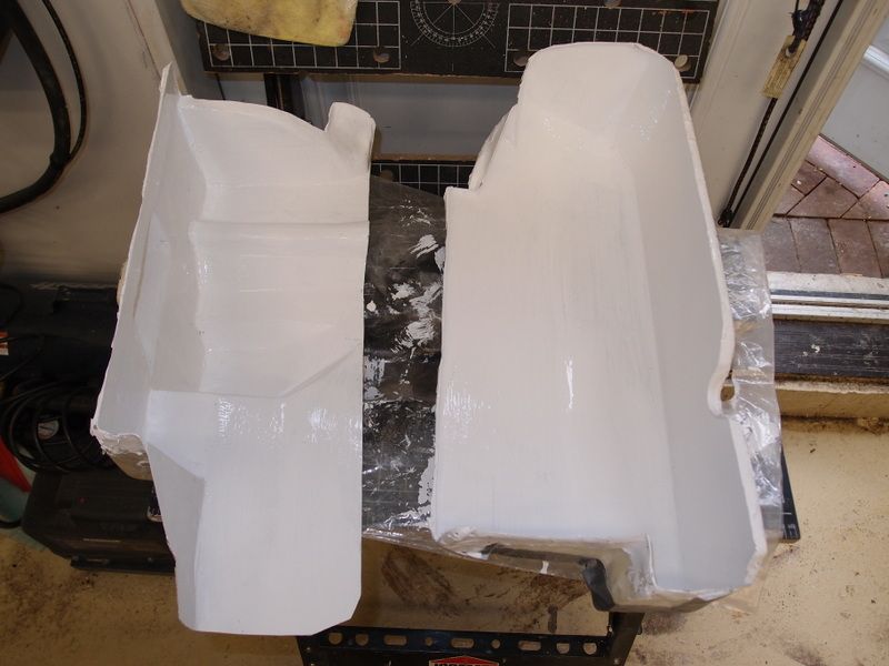
There were some voids in the negative. Repaired with plaster, final sanding and a good coat of latex paint. The paint helps find any imperfections and can help in separating the mold from the final CF intake. If you are going to have visible weave in the final product then the surface has to be as smooth as possible. Otherwise a lot of wet sanding will be needed for the CF part. I had other plans as shown below so even small brush strokes wouldn’t be a problem.
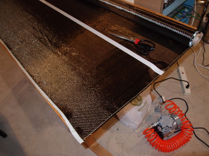
Now the fun part… mmm carbon fiber! I used a 5.8oz 2x2 weave fabric as it would be easy to work with and fold / layer into the mold and have enough strength (http://www.aircraftspruce.ca/catalog...bigraphite.php). Use masking tape where you cut the fabric. Without this the weave will unravel very easily and damage the fabric.
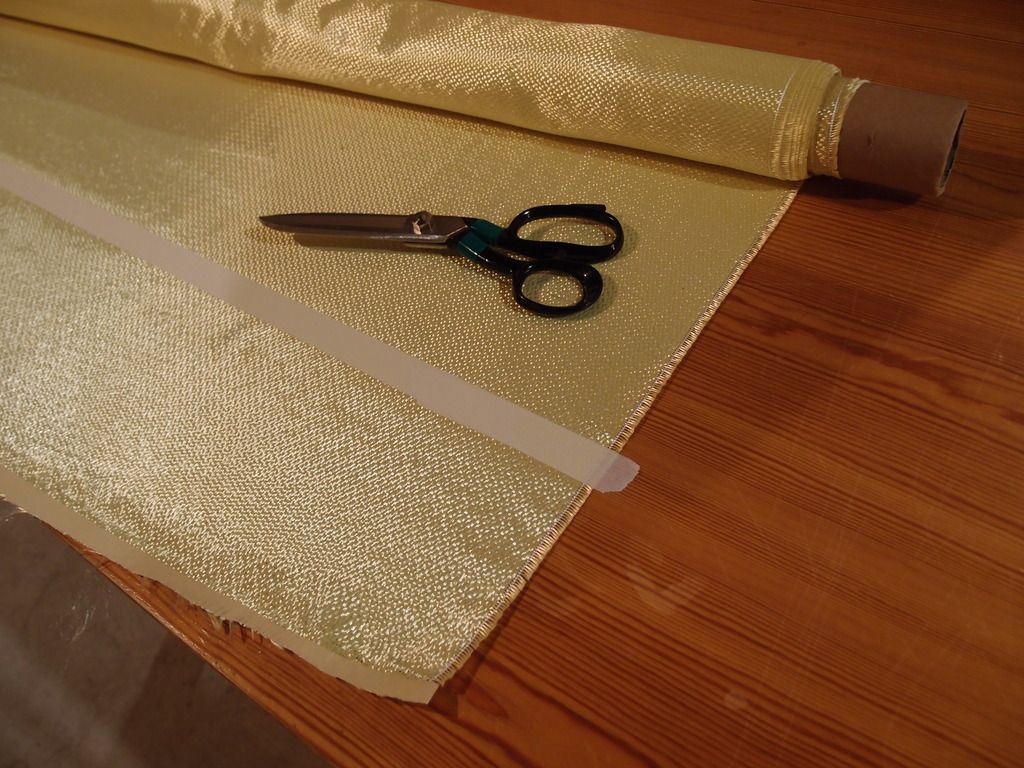
I also used some Kevlar in the build for its sound qualities. A CF intake make a great racecar sound at WOT. However I don’t want to wear ear plugs or fail the sound check at the track. This is where Kevlar helps. It deadens the sound and takes that “turn it to 11 sound” down a notch. Can’t really comment on the difference it makes as I did not build another intake without it to compare. I would probably need more of it than used here to make a big difference though. As an FYI Kevlar needs to be cut with special scissors.
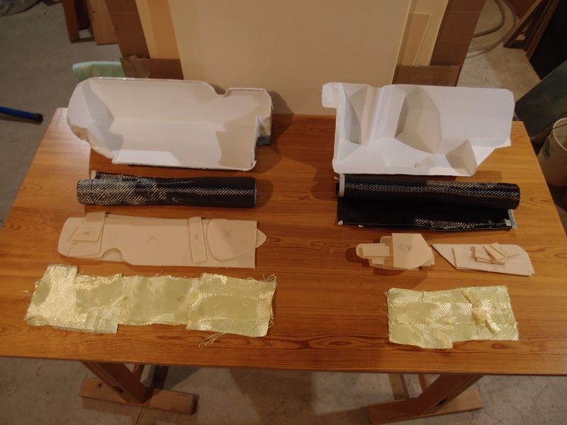
Planning all the bits and having everything precut is important before even getting close to mixing the resin. I used a sandwich build: CF fabric – foam core – CF – Kevlar. This is strong enough for an intake. You would need to build up a CF body panel differently (e.g. more layers oriented in different directions).
The foam core is very light and gives much more strength than simply adding more CF layers, and it is cheaper too. It is a divinylcell PVC foam, 1/8 inch thick, high compression strength, fire resistant and can be vacuum formed. Also important is that it is compatible with the resin being used or it might just melt away on contact. (http://www.aircraftspruce.ca/catalog...nycellfoam.php)
The resin used was Poly-Poxy (http://www.aircraftspruce.ca/pages/c.../polyepoxy.php). Good physical properties and very easy to use in a layup.
Steps:
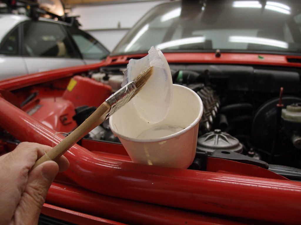
1) prep the mold with mold release wax
2) mix resin in small batches as per instructions
3) brush resin onto waxed mold
4) layup the first CF layer using a brush to wet out the fabric (don’t create pools)
5) add the foam core and wet it as well
6) add the inside CF layer and wet out again
7) add Kevlar and wet out
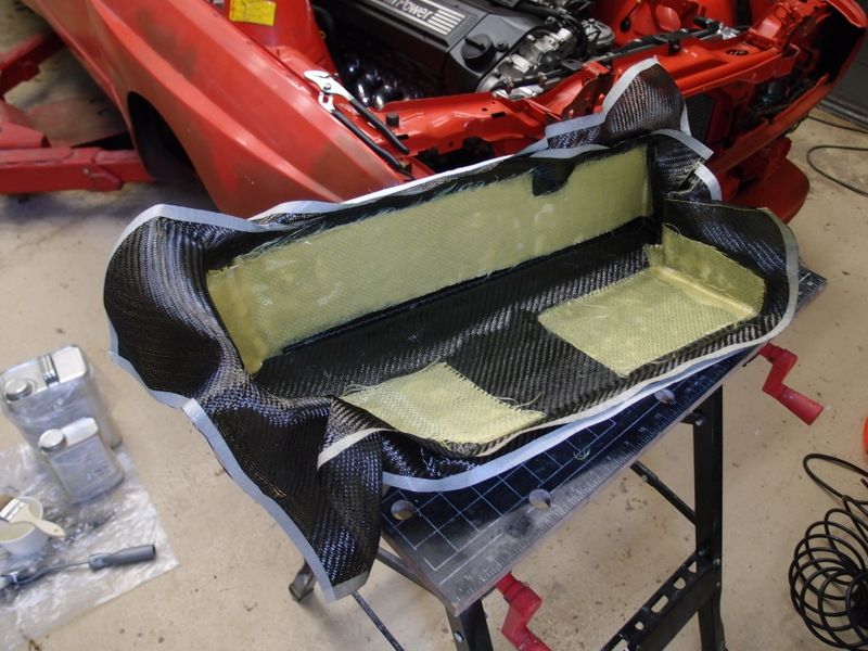
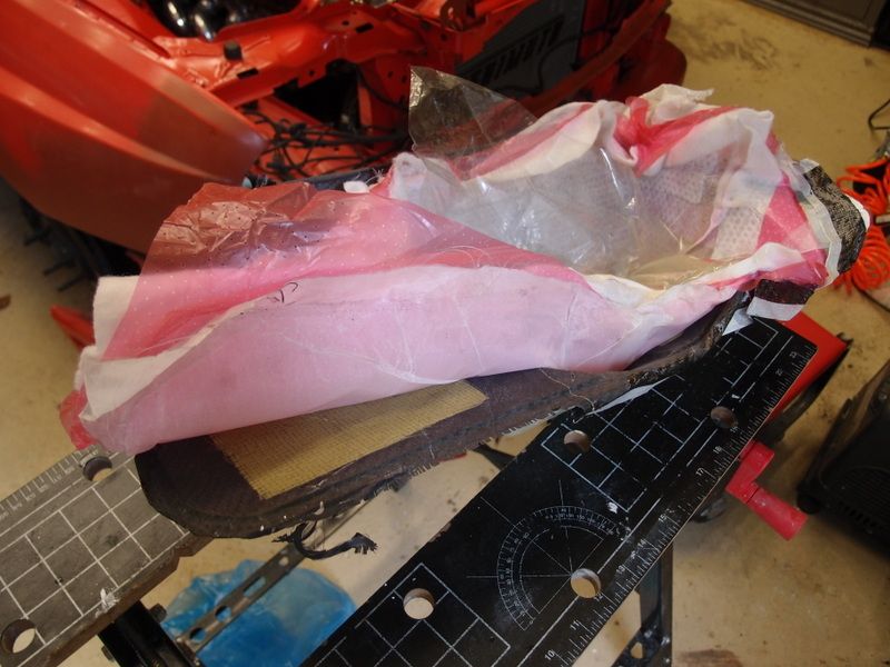
This is after step 7. You will need some excess fabric and trim it later. Due to the compound curves and fabric folding some sections have more than just the 2 layers of CF. Note resin in background.
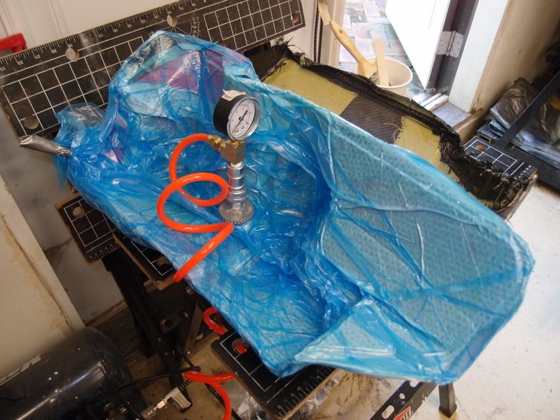
The next part involves vacuum bagging. It is almost a must with 3D shapes and tight corners. It makes the part fit the mold without voids / distortion, gets rid of excess resin, and increases the strength to weight ratio for the part. Too much or too little resin makes the part weaker and/or heavier.
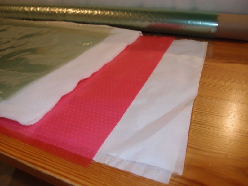
The layers:
1) peel ply – placed against part and separates easily from the cured resin
2) perforated sheet – allows air and resin to escape
3) breather ply – basically a fluffy layer that lets the vacuum spread throughout the part
4) vacuum bag – fancy sheets or a large plastic bag that will fit the part
Layer 1 on bottom.
Under vacuum…
Wait for the cure time. It will depend on the resin, ambient temperature, etc. Check that the leftover resin has cured. Mine need about 24 hours…
Now peel it apart…
Now make the cut outs for the trumpets, MAF, ICV, etc. For the trumpets the hole should be the exact size of the inside diameter. The cut outs will leave rough edges and expose the foam core. This is really a problem at the trumpets as it would create turbulent flow. I coated the raw edges with resin, let it cure and sanded smooth.
The inside and outside trumpet halves are now epoxied to their respective positions (inside /outside for cylinders 1 – 6). JB weld worked well with this resin. Use the marine version as it is more resistant to the elements. I scavenged the various connectors from the OEM S50B32 plenum. I epoxied the appropriate metric nuts so the connectors / sensors could be removed as needed. The ugly epoxy excess is sanded away. The 2 intake halves are trimmed and epoxied together and the excess sanded away. Careful not to sand to hard over the CF or you could easily get down to the bare CF fabric.
As if I did not already sink enough time into this project… I decided to make the “BMW M Power” lettering in 3D on the intake to match the valve cover. So yet another mold and layup…
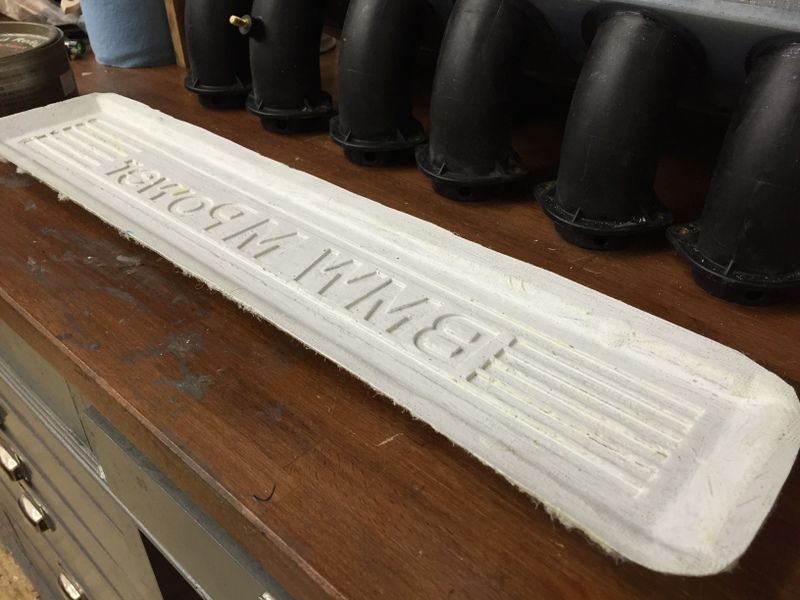
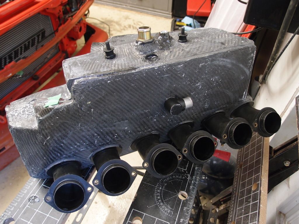
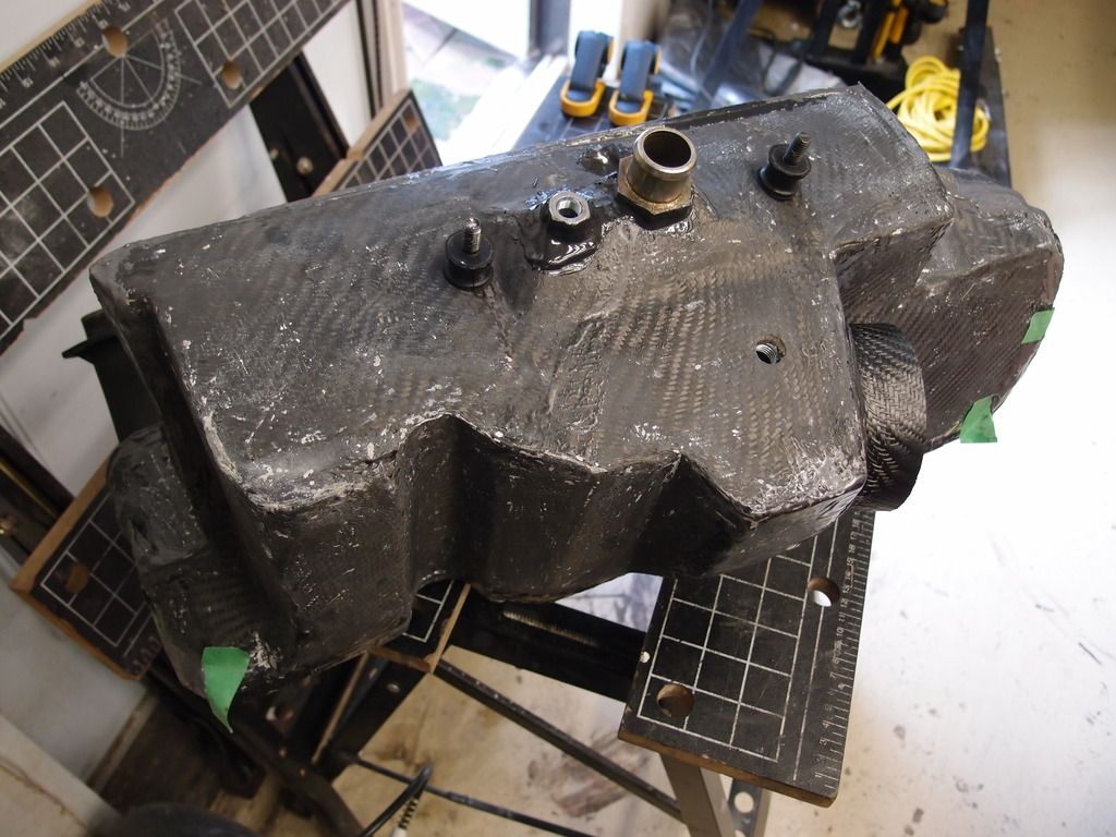
This was simply epoxied onto the top of the intake. Then everything was primed, painted with “hammered paint” (has a cast metal texture when dry) and then painted with black crinkle paint. This gave it a look / feel like the OEM valve cover. The letters were masked off and later painted with an aluminum colour.
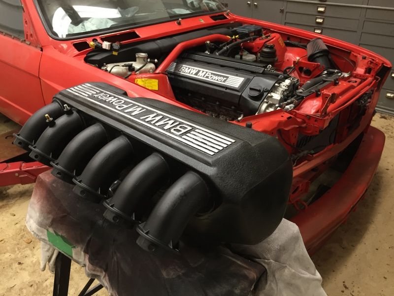
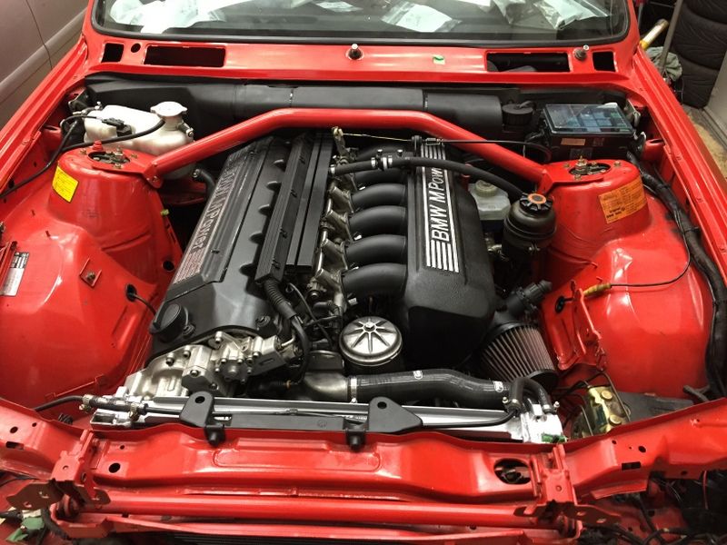
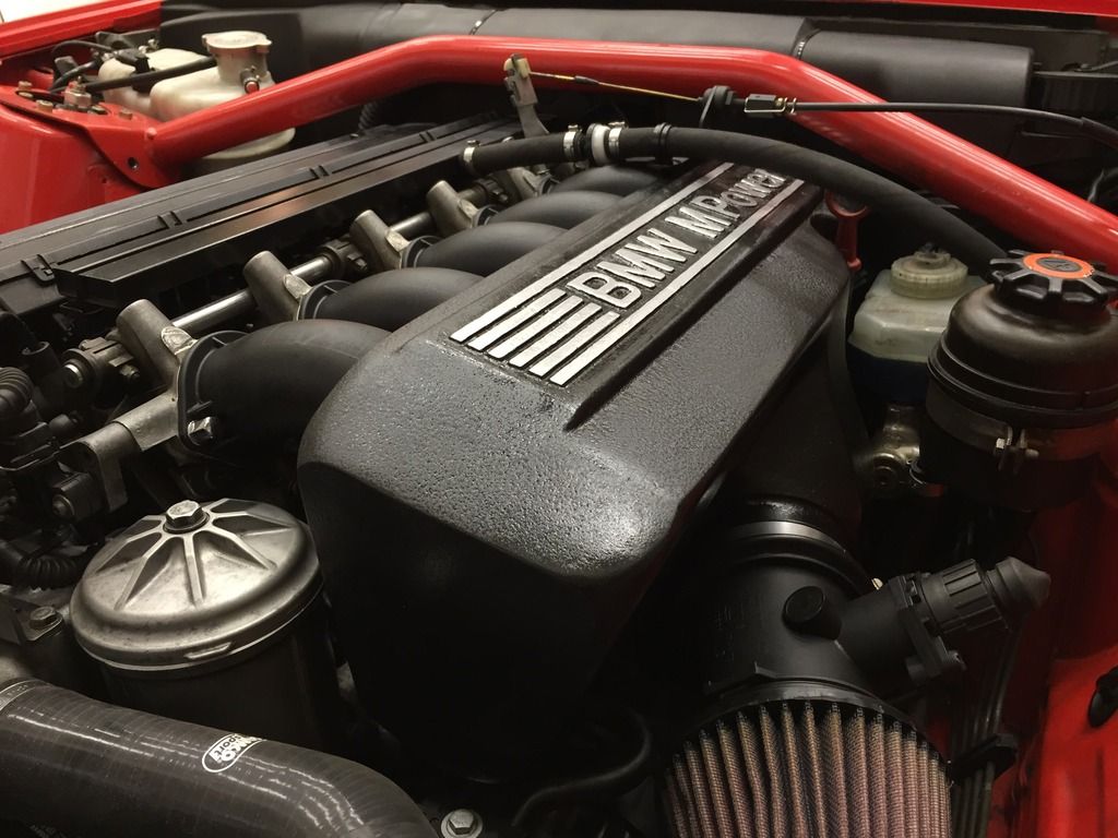
The air filter is temporary. Planning on a CF enclosure to include the E30 headlight cover. That’s it for now!
I know it is a lengthy post. Hey, I don’t post often but when I do… :popcorn:
I am not a composite expert or automotive engineer so keep that in mind. The following is self-taught. All of the composite materials can be easily purchased on line. I used Aircraft Spruce. Good selection and very knowledgeable staff. This could also be done similarly with fiberglass to keep costs down.
The goals:
1) make any mods bolt-on so I could go back to original anytime (S14 and dog-leg trans are in storage)
2) keep brake system / ABS OEM (didn’t want to drill the firewall, loose the booster)
3) keep OEM S50B32 trumpet length (happy with original tune / output)
4) keep an OEM look in the engine bay
5) play with composites
Obviously, the S50B32 plenum won’t fit with the OEM brake booster. However the trumpets do clear the booster with space for air flow. Better clearance is possible if the trumpet ends on the 5 and 6 cylinders are rotated forward a bit.
“Rotating” the trumpet ends involves cutting them at the mid section. All 6 were cut as this would be needed for the final assembly.
The most time consuming part was creating a 3D model of the intake. This would then be used to create a “negative” mold needed for the CF layup.
The model was made from Styrofoam, spray glue (3M), household plaster and latex paint.
Using OEM plenum bracket with rubber mounts.
Needed to clear brake booster/fluid reservoir, PS reservoir, oil filter housing, dipstick, strut bar, and hood when closed as well as have air space around alternator for cooling. Also need to plan spots for the MAF connection, ICV, intake temp sensor, oil rebreather, oil return to pan (not all visible here).
The volume of the intake is bigger than the original but the trumpets and opening to the MAF are basically unchanged. Not expecting any HP gains and hopefully no loss either. The inside space and distance of the trumpet openings to the inside walls are very close to the original. This is important to keep the air pressure waves as close to the OEM tuning as possible. It is hard to show with pictures. Here is the end of the trumpet opening and inside space of the OEM S50B32 plenum.
The styrafoam is painted with latex paint to make surface finishing easier. The styrafoam keeps showering snowflakes otherwise. Looks very crude now.
After several rounds of plaster, sanding, test fitting and one last coat of latex paint I ended up with this…
A mold release wax was applied in several coats to make sure the negative mold separated from the model. (http://www.aircraftspruce.ca/catalog...dRelease15.php)
The negative mold was made out of fiberglass. Cheap and strong enough for this bit. Basically glass mat and resin. Sorry no pic of the in progress. Here is the cured product with the model still trapped inside.
Given the tight curves in some sections the negative and model are actually locked together physically. One could make the mold in sections that separate to deal with this. Since this was a one-off project I used a destructive approach (parts of the model would be broken once the mold was done). A dremel is used to cut the fiberglass layer into two halves.
There were some voids in the negative. Repaired with plaster, final sanding and a good coat of latex paint. The paint helps find any imperfections and can help in separating the mold from the final CF intake. If you are going to have visible weave in the final product then the surface has to be as smooth as possible. Otherwise a lot of wet sanding will be needed for the CF part. I had other plans as shown below so even small brush strokes wouldn’t be a problem.
Now the fun part… mmm carbon fiber! I used a 5.8oz 2x2 weave fabric as it would be easy to work with and fold / layer into the mold and have enough strength (http://www.aircraftspruce.ca/catalog...bigraphite.php). Use masking tape where you cut the fabric. Without this the weave will unravel very easily and damage the fabric.
I also used some Kevlar in the build for its sound qualities. A CF intake make a great racecar sound at WOT. However I don’t want to wear ear plugs or fail the sound check at the track. This is where Kevlar helps. It deadens the sound and takes that “turn it to 11 sound” down a notch. Can’t really comment on the difference it makes as I did not build another intake without it to compare. I would probably need more of it than used here to make a big difference though. As an FYI Kevlar needs to be cut with special scissors.
Planning all the bits and having everything precut is important before even getting close to mixing the resin. I used a sandwich build: CF fabric – foam core – CF – Kevlar. This is strong enough for an intake. You would need to build up a CF body panel differently (e.g. more layers oriented in different directions).
The foam core is very light and gives much more strength than simply adding more CF layers, and it is cheaper too. It is a divinylcell PVC foam, 1/8 inch thick, high compression strength, fire resistant and can be vacuum formed. Also important is that it is compatible with the resin being used or it might just melt away on contact. (http://www.aircraftspruce.ca/catalog...nycellfoam.php)
The resin used was Poly-Poxy (http://www.aircraftspruce.ca/pages/c.../polyepoxy.php). Good physical properties and very easy to use in a layup.
Steps:
1) prep the mold with mold release wax
2) mix resin in small batches as per instructions
3) brush resin onto waxed mold
4) layup the first CF layer using a brush to wet out the fabric (don’t create pools)
5) add the foam core and wet it as well
6) add the inside CF layer and wet out again
7) add Kevlar and wet out
This is after step 7. You will need some excess fabric and trim it later. Due to the compound curves and fabric folding some sections have more than just the 2 layers of CF. Note resin in background.
The next part involves vacuum bagging. It is almost a must with 3D shapes and tight corners. It makes the part fit the mold without voids / distortion, gets rid of excess resin, and increases the strength to weight ratio for the part. Too much or too little resin makes the part weaker and/or heavier.
The layers:
1) peel ply – placed against part and separates easily from the cured resin
2) perforated sheet – allows air and resin to escape
3) breather ply – basically a fluffy layer that lets the vacuum spread throughout the part
4) vacuum bag – fancy sheets or a large plastic bag that will fit the part
Layer 1 on bottom.
Under vacuum…
Wait for the cure time. It will depend on the resin, ambient temperature, etc. Check that the leftover resin has cured. Mine need about 24 hours…
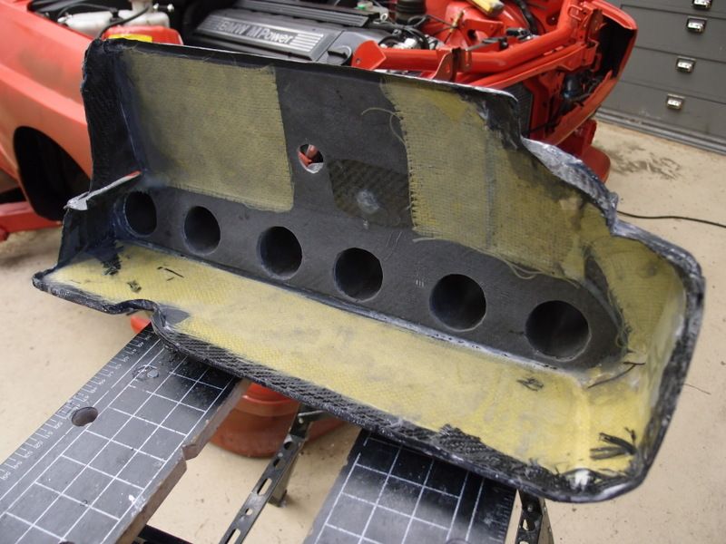
Now peel it apart…
Now make the cut outs for the trumpets, MAF, ICV, etc. For the trumpets the hole should be the exact size of the inside diameter. The cut outs will leave rough edges and expose the foam core. This is really a problem at the trumpets as it would create turbulent flow. I coated the raw edges with resin, let it cure and sanded smooth.
The inside and outside trumpet halves are now epoxied to their respective positions (inside /outside for cylinders 1 – 6). JB weld worked well with this resin. Use the marine version as it is more resistant to the elements. I scavenged the various connectors from the OEM S50B32 plenum. I epoxied the appropriate metric nuts so the connectors / sensors could be removed as needed. The ugly epoxy excess is sanded away. The 2 intake halves are trimmed and epoxied together and the excess sanded away. Careful not to sand to hard over the CF or you could easily get down to the bare CF fabric.
As if I did not already sink enough time into this project… I decided to make the “BMW M Power” lettering in 3D on the intake to match the valve cover. So yet another mold and layup…
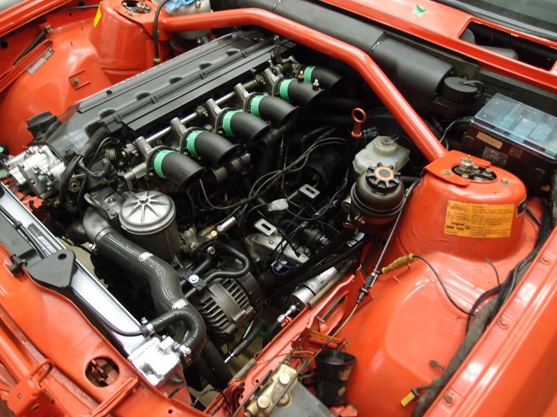
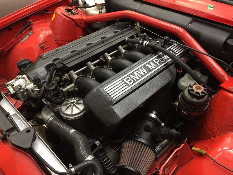
This was simply epoxied onto the top of the intake. Then everything was primed, painted with “hammered paint” (has a cast metal texture when dry) and then painted with black crinkle paint. This gave it a look / feel like the OEM valve cover. The letters were masked off and later painted with an aluminum colour.
The air filter is temporary. Planning on a CF enclosure to include the E30 headlight cover. That’s it for now!
 Incredible! That almost looks factory.


Comment