Announcement

Collapse
No announcement yet.

N52 Swap Discussion

Collapse
X
 
  • Filter
  • Time
  • Show
Clear All
new posts

    Pre-warning on exhaust work for CNC bending, these typically have bends very close together which requires specialized tooling. My advice to you is that if you want an affordable piece to leave as much space as possible between bends. The larger the tube diameter the more space required.

    ​​​​
    Your signature picture has been removed since it contained the Photobucket "upgrade your account" image.

    Originally posted by TimKninja
    Im more afraid of this thread turning into one of those classic R3v moments, where Pizza gets delivered.

    Comment


      Originally posted by hubcapboy View Post
      RIP your inbox when hoveringuy finds out about you. He might already be in his truck eastbound.

      My plan for the engine arms is to make them very similar to the factory m20 steel arms... flat pieces that define the geometry. I'm expecting to end up with a fixture for assembling pieces in the future (probably something that'll mount to my spare block) so there'll be an opportunity to reproduce the geometry with tube, but I don't see it being cost effective for this first pass.

      What I'm very interested in with regard to a CNC tube bender is building downpipes. My plan has been to take factory N52 exhaust manifolds, hack them off below the collector (retaining the near-port O2), and V-band to a downpipe to connect to the factory e30 center section location. Someone was selling these for e90's at one point without much success as cat elimination (one of the attachments). I spent about 5 minutes confirming that my (I think e60) manifolds are a hopeless misfit for the chassis. There's some european factory manifold (the only attachment with cats) which has a little bit more of an equal length collector section, but certainly at the expense of space, and v-banding at the larger collector cross section would be an extra challenge. I've thrown an image of the supersprint type headers, which a few different companies sell. I'm not completely sure how these are supposed to work, because they move the near-port O2 sensor waaaaaaaay down and I'm not sure how that can work for engine management... It's a mystery to me whether the near port O2 sensors are near the ports for better sampling, or because the cats need to be closer to the ports to heat up as quickly as possible and that's the only place to put a pre-cat sensor...

      All that being a preamble to say... If you have the capability to scan and bend what will undoubtedly be a hideous attempt at a pair of downpipes when I'm done, that'll be one of the hurdles I anticipate crossed off, and we'll end up with CAD documentation of the pieces so they can be duplicated going forward. I expect the pieces will look very similar to the e90 downtubes, but with no O2 bung (correct me if I'm wrong, Nando, just the near port O2 will be needed with the cat delete) and a V-band at the top instead of a weld to the manifold.
      Why not fabricate those mounts out of aluminum and eliminate the differing metals issue altogether?

      Anyway, I can adjust the DME for the different O2 sensor position. I've already done so on several cars.I basically just copy the settings from MSS70, where the S54 manifolds have a similar distance from the ports to the N52 SS headers. Works like a charm. The MSS70/MSV70 feedback loops are actually highly complex, fast, and adjust quickly to feedback from the widebands.

      BTW, the N52 doesn't need a MAF because of this (it was designed without it, and added later for emissions). It can run purely on the O2 feedback, even with headers (with the above adjustments). I haven't run a MAF since like 2016.

      I owe some people responses - buys trying to meet a deadline. I don't even go outside right now. :(
      Build thread

      Bimmerlabs

      Comment


        MIG welding mild steel is like hot glue compared to aluminum (to me anyway). I've already got the equipment and I'm fairly confident in my ability to eyeball weld strength. Aluminum would be a far better choice if I had a different skillset, and I expect the cad and fixtures I'll end up with will be useful for that in the future.

        Comment


          so, ive been staring intently at subframes on the internet for the better part of two days. My latest thought was to make a dual tube subframe. Move one tube out in front of the steering rack (larger diameter) and a second tube behind the steering rack (smaller diameter). The front tube would provide the majority of the strength to the subframe, the rear tube would be used primarily to mount the steering rack and provide some extra rigidity near the balljoints. The sway bar would have to flip to mount in front to clear the engine. The outer ends of the subframe would be boxed to mount the balljoint and the engine mounts could be relocated to use the stock z4 arms.

          turns out that a simiilar design exists (though for lots of money) from bmp conversions: https://bmpconversions.com/product/b...ud-engine-bed/

          Looks like they had to make some minor changes to the pan, would be easier with a steel pan. You can forget about getting that steering rack out, but that honestly isnt a big concern for me.

          those who have already mounted the engine, did you use the e30 round hole or the slotted hole in the subframe. I think back when i did an s52 swap i used the slotted hole for the mount because it was wider, if this is the case i think you could get an inch toward the rear and not interfere with the balljoint.
          Your signature picture has been removed since it contained the Photobucket "upgrade your account" image.

          Originally posted by TimKninja
          Im more afraid of this thread turning into one of those classic R3v moments, where Pizza gets delivered.

          Comment


            I'd definitely seen the BMP kit before I started in on all this, but at that point it was one or two very blurry pictures on a facebook post. I don't think they'd finished the first car yet. Dont forget that the BMP kit is based on the M5x engine block and pan, which means even after all that modification to the subframe, relocating the sway bar, and re-mounting the steering rack (and modifying the oil pan) you still have to fix the "where does the engine go" problem to build engine arms out to the motor mounts.

            I'm honestly not sure that modifying the oil pan *is* easier than building one from scratch once the work is done once, although like you say starting with a steel pan makes it much easier. My concern is that it isn't particularly reproducible (that is, IF I finish this and say "ok go for it guys. it totally works" my best guidance is "ok kinda chop 4" by 3" out here near where the blob is and add about 6" here."

            Since this thread started there's a youtube channel that's done (I think it's done anyway) an N54 install. Nando mentioned he worked with him above:

            https://www.r3vlimited.com/board/for...t-garageaholic

            As much as I respect this guy for the amount of work he put into it, and as much as I recognize that he's vastly more knowledgeable than me... and it looks like his documentation of the N54>e36 is incredibly detailed and I expect the e30 version will be as well... I don't see how this guide can be anything more than a documentation of how he completed a one-off (still immensely helpful if you want to reproduce it). He definitely had to move the steering rack (an option if you want to leave the sump unmodified), and his subframe is hand-fitted to the car. It's an extraordinary accomplishment, but not a huge step towards buying a kit and dropping a junkyard engine in over a few weekends like you can with an M5x. Frank (if you end up here, hi Frank) is just building a completely custom car, although there's a TON to learn from it for this application as well.

            Comment


              Here's an aluminum tube for extending the oil pickup tube.

              I finally took the oil pan off today. Then I unfastened the bolts holding the oil pickup along with a couple others. I then relocated the pickup tube to the holes toward the rear of the bedplate. Had to swap some screws around because of different lengths. Then I held the oil pan back up to the block and there was an interference that didn't allow the pan to sit flush by about 3/16". I determined it was the bottom of the pickup tube. I trimmed roughly 3/8" off the bottom and reinstalled everything. Seems to fit fine with no interference detected. Once I reach the point where I'm ready to cut into the pan, I'll see what kind of clearance remains between the pan and the bottom of the tube.

              So anyways.... The distance between the bolts for the pickup tube is 91mm. (Coincidentally that's the same distance between the bolts that hold the intake manifold on the head.) By moving the tube assembly over by one set of holes, I needed a tube to make up that difference. I just modeled the end of the plastic piece and took a couple measurements of the oil pump bore. (30mm dia.) Here's a print of the part. I haven't machined it yet. Could be awhile because of.....

              I also have been working on a spacer for the mismatch between the N54 manifold and the N52 head. The spacer is 3/8" thick (10mm) and longer 60mm bolts will be needed to make this work. I couldn't find any 7mmx60 studs anywhere,
              so bolts are the 'only' choice. Not sure if this piece is really necessary, but I have the parts and the time, so I ended up with this.


              Click image for larger version  Name:	20200707_151257 (2).jpg Views:	0 Size:	87.4 KB ID:	9937239 Click image for larger version  Name:	20200707_151449 (2).jpg Views:	0 Size:	72.3 KB ID:	9937240 Click image for larger version  Name:	20200707_151513 (2).jpg Views:	0 Size:	68.2 KB ID:	9937241 Click image for larger version  Name:	20200706_164025 (2).jpg Views:	0 Size:	84.3 KB ID:	9937242
              Attached Files
              Last edited by LukeJ; 07-08-2020, 09:31 AM. Reason: Removed pdf for update/correction.

              Comment


                It's not a coincidence - the cylinder spacing of every BMW "small" 6 since the M20 is 91mm. :)

                What are you making the spacer out of? I need to make something similar for my S54 throttles..
                Build thread

                Bimmerlabs

                Comment


                  Originally posted by nando View Post
                  It's not a coincidence - the cylinder spacing of every BMW "small" 6 since the M20 is 91mm. :) .
                  They couldn't get an even 90mm huh? ;-)

                  I plan to make the spacer out of aluminum plate. If you look closely at the mock-up.... The dashed lines represent the 'o-ring' groove on the back side. OEM gaskets will fit there. I 'smoothed' the transition between N54 and N52 with a 10 degree draft angle. That way it could be machined with 'off the shelf' tools and not need 3D machining. Just a 10 degree tapered endmill.

                  Comment


                    We should share CAD files for the intake ports to facilitate cheap adapters. I made one a long time ago for N52/S54, but never tried to do a prototype.

                    the ports on the S54 are only a couple mm bigger, but the bolt pattern is much different, plus the OFH interferes with a bolt on cylinder #1. With a tapered adapter, I think it would both serve to make the stacks longer (already anyway, since part of the manifold is built into the head), and reduce the section area to keep velocity up
                    Build thread

                    Bimmerlabs

                    Comment


                      I was originally going to design it to be thinner. But 55mm length bolts are not a 'normal' thing. The other factor was the off the shelf tooling and the 10 degrees is perfect for the difference in profile over the 3/8" distance.

                      The N52 head port is a little less narrow on the top and bottom compared to the N54 manifold. About 1mm per side. There would be a step, and the air would 'tumble' I believe. Perhaps insignificantly. I just thought 'smoother' would be better.

                      I think the velocity may decrease slightly because the N52 opening has a bit more surface area. Perhaps by smoothing the transition, the 'negative' effects are reduced or nullified?

                      PM me about the CAD stuff. I'd be willing to help out.
                      Last edited by LukeJ; 07-07-2020, 11:06 PM.

                      Comment


                        Trying to find my CAD file. Looking at my S54 throttle pics again makes me want to try a little harder. :p
                        Build thread

                        Bimmerlabs

                        Comment


                          I found an error with the pdf I posted yesterday. I previously made the part 91mm OAL. But it needed to be 91mm from the o-ring end to the bottom of the counterbore on the opposite side.

                          Things like this are why there are usually more than one person in an engineering team. Also, why I'm reluctant to share this stuff until I've tried it out for myself.

                          Here's the corrected pdf. I edited the above post and changed the pdf there too. I just didn't want any confusion.
                          Attached Files

                          Comment


                            Can anyone point me towards some concise information about adapting wiring harness' and how to wire the C101 for an engine swap?


                            Thanks!!

                            Comment


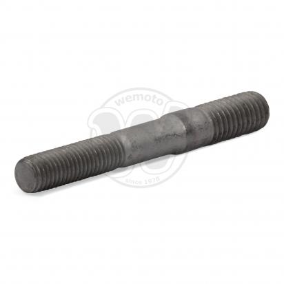
                              RE: M7 x 60mm studs
                              would something like these M7 to M8 studs work? May need to increase the hole size in the manifold

                              Looking for Exhaust Stud M8x60mm to M7 Pitch 1mm for your motorbike? At Wemoto UK we have what you need. Visit our online store today!
                              Your signature picture has been removed since it contained the Photobucket "upgrade your account" image.

                              Originally posted by TimKninja
                              Im more afraid of this thread turning into one of those classic R3v moments, where Pizza gets delivered.

                              Comment


                                Originally posted by hubcapboy View Post
                                (the capacity coming from the pretensioning of the bolts pressing the surfaces together and never engaging the bolt in shear)
                                This is how EVERY bolted joint works.

                                Comment

                                Working...
                                X