
-
Small update, but I was able to shoehorn the micro-USB bulkhead adapter into my enclosure despite all of the prototyped circuits I have taking up space with my own use-case:
Leave a comment:
-
-
See my nearly simultaneous post, short answer: yes.
Longer answer: how you need to do it depends on your exact setup, but as things sit right now it shouldn't be difficult. For example, I have my wideband O2 wired to my Megasquirt 2, and the MS2 sends the AFR via CAN to the PCB pictured above; I push the "AFR" button on the simulated 13-button OBC, and it brings up a VDO AFR gauge that uses the data coming from the Megasquirt. If you're running a stock ECU, the difference would be that you wire the wideband's analog output directly to my PCB and read it in that way, rather than via CAN (might need to build a simple voltage divider to ensure the wideband's analog output never exceeds the 3.3V limit of the Teensy analog input pins, or configure output curve via wideband software).
That's exactly what I do with oil and fuel pressure, I have analog sensors installed whose outputs are wired to a couple of the PCB's analog inputs. Coding for reading these values and sending them to the display can be done in Arduino IDE, and is basically copy-paste of what I have already done. The display has its own GUI editor software, which if you can handle Arduino stuff is a breeze.Leave a comment:
-
For now, PM me if you're interested. Things are still in a bit of a testing phase but I can get a kit out to you relatively quickly if you're interested. As such, I'd like to discuss your desired implementation to make sure it's a good fit for this stage of the project (the hardware you have, your project scope, and your programming skill level).
At some point there may be totally plug-and-play versions for common vehicle setups, but this is really intended as a moderately DIY, highly modular system that can be adapted to work for more than just e30+Megasquirt (like my use case). Think e30 + swapped engine with CAN (e.g. S52/S54, etc.), non-e30/BMW, and different locations and sizes of touchscreen (or no touchscreen at all). In exchange for that modularity and high level of adaptability comes some DIY. The closer you are to e30+Megasquirt the more I can help you with a nearly turnkey solution, and the simpler your project scope (e.g. just displaying gauges and not controlling anything) the easier it will be.Leave a comment:
-
That 13 button OBC screen is awesome retro look! An add-on board that can sit in the engine bay and communicate back over CAN would be cool as well.
Any options for stock ECUs and adding additional sensors to display on the screen (wideband O2, additional coolant temp, oil temp/pressure).Leave a comment:
-
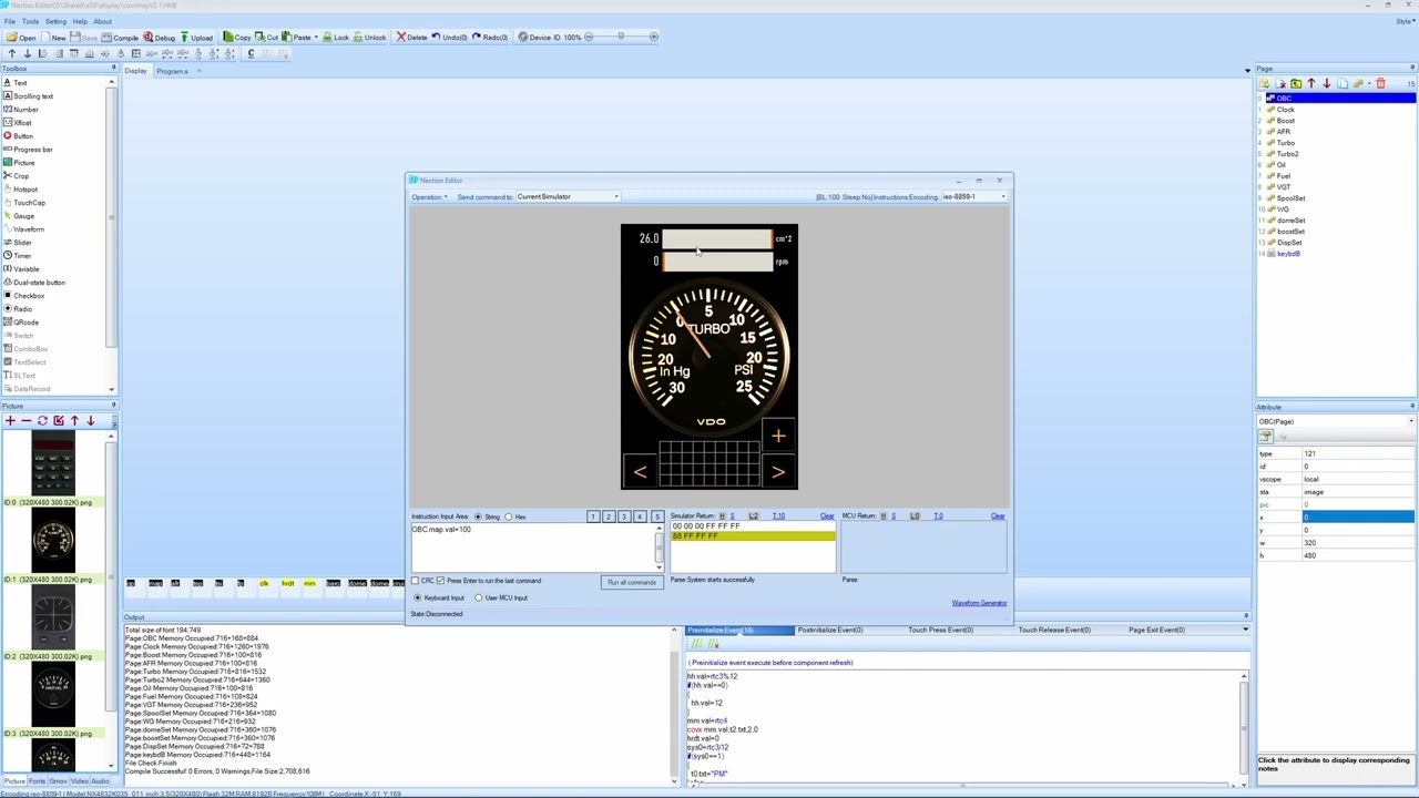
Installed and running! Here are a couple sample screens, there are 12+ visualizations. The OBC "buttons" are soft buttons that take you to the relevant gauge when pressed, and there are some tuning pages as well, such as wastegate control PID parameters, boost control modes, etc. I'll do a more detailed writeup and probably a video in the future.
Actual display subassembly, drop-in replacement for stock OBC (other than wiring). Yes, it clears the fan speed switch and AC/recirc switch (barely - the 3.5" screen's control PCB is larger than the "pocket" that the stock OBC fits into so it was very tricky getting this to go together).
Custom PCB running Teensy 4.0, for interfacing between CANbus, any desired sensor inputs, switchable outputs, touchscreen display, etc.
In my case I've configured the board via jumper wires to:- run the display (power it, send data, receive user inputs)
- read 4 pressure sensors (two of which I've wired up low-pass filters in the built-in prototyping/breadboard area, cleans up noisy signals)
- run the stock econometer (low-side MOSFET switch built into board with 12V pullup circuit prototyped on the board)
- control two boost control solenoids (low-side MOSFET switches built into the board)
- trigger a relay that powers my VGT turbo's actuator (low-side MOSFET switch built into the board)
- read real time data from MS2 via CAN (built-in CAN transceiver, CAN controller is built into Teensy 4.0)
- send real time data to MS2 via CAN
- control VGT turbo via CAN
- read real time data from VGT turbo via CAN
- read turbo shaft speed sensor (VR sensor signal conditioner is built into the board)
- read EGT probe (amplifier built into the PCB so probe wires directly to it)
I'm also considering designing an "add-on" board that would be dedicated to analog inputs, running a separate Teensy 4.0 and communicating to this one via CAN. Expanding like this would allow a whole lot more analog inputs, and I would include pressure transducers directly on the board so you "wire" in vacuum/pressure lines rather than locating pressure sensors throughout the engine bay and needing to run wires everywhere. This would also possibly include optional digitally-configurable low-pass/antialiasing filters in the signal paths to ensure clean signals for any use case. For example, I read my wastegate's dome pressure into a inner and outer PID control loop to get close-loop dome pressure boost control using onboard compressed air - due to the operating frequency of the solenoids that feed/vent the wastegate dome, there's a lot of oscillation in the signal sometimes - low-pass filtering this signal gives much better performance. Likewise with pre-turbo exhaust manifold pressure, it can be a pretty noisy signal due to the extremely transient nature of the pressure in the manifold, low-pass filter cleans up the signal so it's easier to understand what's going on.
Last edited by mikey.antonakakis; 05-07-2024, 08:16 AM.Leave a comment:
-
Here's the main update: managed to at least physically fit a much larger touchscreen display in the stock OBC location - higher resolution, too: now 480x320 vs. 320x240. Also managed to match the stock plastic texture pretty well - the sheen is a little too glossy, but a light coat of flat back paint will get it close to perfect.,
Still need to test out the new PCBs and new display in my own car, will happen soon.
Leave a comment:
-
Mildly exciting updates coming soon... assuming it all works out after some brief testing.Leave a comment:
-
Leave a comment: