
So, having taken a (more than a year now...) long break from my instrument cluster design due to the chip shortage, I am back - with a check panel replacement. I actually started this project about a year ago but quite literally 80% of the BOM (aside from passives) went out of stock between beginning the design and getting ready to order the bare PCB, so I said fuck it and decided to focus on getting the car out to the track. The reason I have decided to revist this while leaving the cluster project on hold is mostly to feel out where things are at in terms of component availability, this board is relatively simple and not that much of a time sink if I can't make it work. The industry is still quite rough in some spots but other areas are starting to see improvement, so I am optimistic I can return to semi-hobby prototyping of some of my E30 schemes.
Anyway, I have completely refreshed the design, including moving to a significantly more expensive, overkill and less popular processor, and I should have bare boards in hand for the first prototype in about a week (they just left China). I have all the critical parts aside from the desired GPS module sitting on my desk right now.
3D render of the prototype PCB:

This project is being designed in two stages - the first stage that has already been kicked off is the quick and dirty prototype. This is being done using relatively easy to deal with parts, all signals are being exposed on the outer layers, and I can 'easily' fiddle and rework things by hand here on the bench as I validate basic mechanical and electrical functionality. I expect there to be a few weeks and weekends of tinkering before actually ordering phase two:

Whoa! The same thing, but in white!
Not really - here is a snapshot of the backside of the two boards:


As you can hopefully see, there are some minor differences aside from the colour. These primarily come down to signal integrity, automated assembly support, and lots of other details that I am happy to get into if anyone is interested in but otherwise I will save you all from being bored to death. Long story short the R1 board (white) is much, much more difficult to debug but should be much more robust as a device in the car. The R1 board will likely also undergo some minor changes before being actually ordered, but this will be based on testing done on the R0 board that I should have in hand shortly.
Note that the big ugly grey thing in the above front renders is actually a display - it should look something more like this (I just don't have a nice 3D model, screen image just taken from display manufacturers website and beautifully 'shopped into place):

The hardware feature list, as designed:
Anyway, I hope to be building the prototype up next weekend at the latest - I will update this thread sometime around then.
Anyway, I have completely refreshed the design, including moving to a significantly more expensive, overkill and less popular processor, and I should have bare boards in hand for the first prototype in about a week (they just left China). I have all the critical parts aside from the desired GPS module sitting on my desk right now.
3D render of the prototype PCB:
This project is being designed in two stages - the first stage that has already been kicked off is the quick and dirty prototype. This is being done using relatively easy to deal with parts, all signals are being exposed on the outer layers, and I can 'easily' fiddle and rework things by hand here on the bench as I validate basic mechanical and electrical functionality. I expect there to be a few weeks and weekends of tinkering before actually ordering phase two:
Whoa! The same thing, but in white!
Not really - here is a snapshot of the backside of the two boards:
As you can hopefully see, there are some minor differences aside from the colour. These primarily come down to signal integrity, automated assembly support, and lots of other details that I am happy to get into if anyone is interested in but otherwise I will save you all from being bored to death. Long story short the R1 board (white) is much, much more difficult to debug but should be much more robust as a device in the car. The R1 board will likely also undergo some minor changes before being actually ordered, but this will be based on testing done on the R0 board that I should have in hand shortly.
Note that the big ugly grey thing in the above front renders is actually a display - it should look something more like this (I just don't have a nice 3D model, screen image just taken from display manufacturers website and beautifully 'shopped into place):
The hardware feature list, as designed:
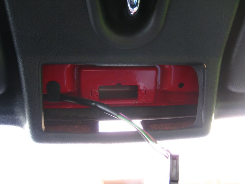
- Full E30 check panel functionality - reads all the same factory signals and can turn on the 'CHECK' lamp in the instrument cluster.
- Intended to mate with factory E30 check panel connector (well, from a 325is - the 318/models without the full wiring harness will need an adapter and obviously won't be able to get all the 325i functionality).
- 9 1 watt high brightness R/G/B fully programmable LEDs.
- 7 2 position toggle switches. These can either be a less expensive (but still very solid feeling, I have some on my desk) easy to flip switch such as SW609 or a locking toggle that is not something you can accidentally flip (the other 6 switches).
- 2 12 position rotary knobs.
- A 1.8" high brightness touchscreen (no multi-touch but works with any driving/racing gloves).
- A USB-C connector on the front panel.
- Light intensity sensors on both the front and back panels, these can ideally be used to monitor cabin brightness and possibly sun-in-your-face and adjust light dimming accordingly.
- A temperature sensor, so you know can better guess exactly how much you are sweating your balls off while ripping around the track.
- An integrated micro-SD card.
- An integrated 10 or 30Hz GPS (A separate antenna will need to be routed all of 3 inches to the windshield). Note that the 30Hz GPS, when I can fucking buy them without a 52 week lead time, is a drop in compatible part that also has an accelerometer and dead-reckoning capabilities.
- CANbus integration - either using the header on the back of the board (J204) or you can solder-jumper the PCB and reuse the factory oil pan level sensor wires. I would generally recommend running new twisted pair all the way to your aftermarket ECU, but I figure plenty of people running an aftermarket ECU probably dumped the basically useless oil pan sensor, and these wires are already in the harness, so it might make life easier having the option.
- A small handful of spare I/O - two analog inputs and two outputs.
Anyway, I hope to be building the prototype up next weekend at the latest - I will update this thread sometime around then.


Comment