
Some of you saw my brainstorming thread about putting a CD43 faceplate onto a newer, somewhat more capable head unit.
Well, I have selected a HU and am actually working on the technical aspects of this now. I'll be posting progress in here, as I make it. The HU is a JVC KD-HDR60.
Right now, I have figured out one half of the electrical / programming side. It took some snooping around to get the data sheets for the LCD controller in the JVC HU, but once I did that it was a fairly simple matter of figuring out which data bit corresponded to which LCD segment (195 segments, 195 1's or 0's to turn each one on/off). I did this with my favorite microcontroller in the world, the PIC12F683. The windows UI was done in Visual Basic.
Pictures are more fun, so I'll toss some in. Here's the setup I was working with to debug this. The LCD was being manipulated through this simple little guy...a PIC12F683 uC, a 5V regulator & a DS275+ RS232-TTL level converter (so the PIC can talk to the PC). The LCD controller just uses a simple 3-wire SPI interface.
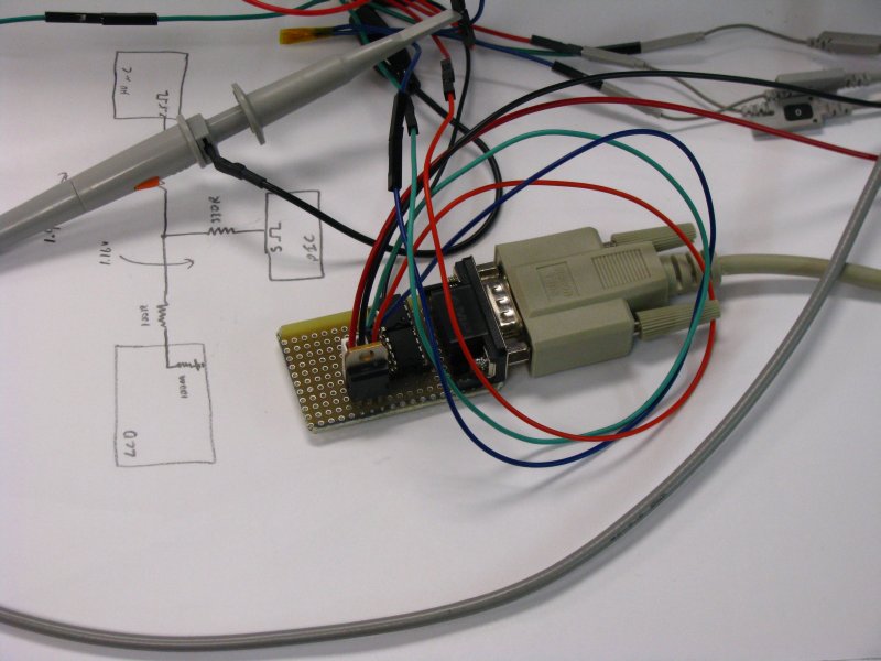
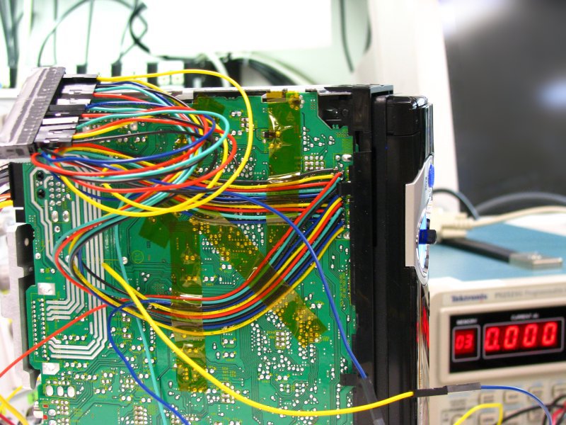
I soldered leads onto EVERY pin of the faceplate connector just in case I needed to check power-on timing or anything. Really though, I just needed the 3 SPI pins & a ground.
Just in case anyone wants "proof" of my nefarious plan to hack crappy car electronics for purposes of world domination...:p
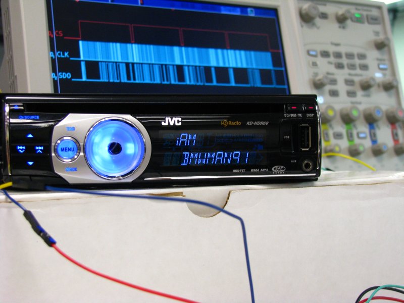
As glamorous as that may seem, it took a solid 90 minutes of hitting the space bar & some arrow keys, and clicking the same button in a windows app to get enough information to do that. I printed out part of the service manual with the LCD section displayed (how convenient!) and checked every single segment. "But bmwman91, why are you messing with the JVC LCD? You wanted to put the CD43 LCD on there right?" Correct. I need to have the display data that comes from the JVC motherboard 100% understood first so I can translate it for the CD43.

This is a screenshot of the UI I made to debug the LCD.

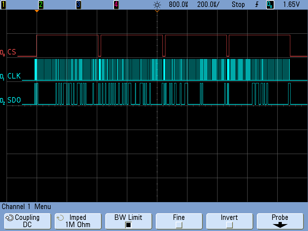
A gratuitous scope shot...
This is the data packet my PIC sent the HDR60 to display "iAM BMWMAN91". The top trace is the chip select line (set it high when you want to tell the LCD controller, "hey I am sending info"), the middle is the clock & the bottom is the data line (the clock signals the controller to read a 1 or 0 at that time). The controller takes 256 bits in, 204 of which are for switching LCD segments and the rest are either for control purposes or unused. It is done in 4 64b sections with an address byte in between. Why? Who knows. It seems a little more complicated than necessary to me.
I'll do my very best not to get more technical than this since it won't really add anything to the story. If anyone wants more of the gory details, I'll be happy to post them (time permitting). My turkey day break is over tomorrow, so progress will probably slow down a bit since I'll be back at work.

Well, I have selected a HU and am actually working on the technical aspects of this now. I'll be posting progress in here, as I make it. The HU is a JVC KD-HDR60.
Right now, I have figured out one half of the electrical / programming side. It took some snooping around to get the data sheets for the LCD controller in the JVC HU, but once I did that it was a fairly simple matter of figuring out which data bit corresponded to which LCD segment (195 segments, 195 1's or 0's to turn each one on/off). I did this with my favorite microcontroller in the world, the PIC12F683. The windows UI was done in Visual Basic.
Pictures are more fun, so I'll toss some in. Here's the setup I was working with to debug this. The LCD was being manipulated through this simple little guy...a PIC12F683 uC, a 5V regulator & a DS275+ RS232-TTL level converter (so the PIC can talk to the PC). The LCD controller just uses a simple 3-wire SPI interface.
I soldered leads onto EVERY pin of the faceplate connector just in case I needed to check power-on timing or anything. Really though, I just needed the 3 SPI pins & a ground.
Just in case anyone wants "proof" of my nefarious plan to hack crappy car electronics for purposes of world domination...:p
As glamorous as that may seem, it took a solid 90 minutes of hitting the space bar & some arrow keys, and clicking the same button in a windows app to get enough information to do that. I printed out part of the service manual with the LCD section displayed (how convenient!) and checked every single segment. "But bmwman91, why are you messing with the JVC LCD? You wanted to put the CD43 LCD on there right?" Correct. I need to have the display data that comes from the JVC motherboard 100% understood first so I can translate it for the CD43.
This is a screenshot of the UI I made to debug the LCD.
A gratuitous scope shot...
This is the data packet my PIC sent the HDR60 to display "iAM BMWMAN91". The top trace is the chip select line (set it high when you want to tell the LCD controller, "hey I am sending info"), the middle is the clock & the bottom is the data line (the clock signals the controller to read a 1 or 0 at that time). The controller takes 256 bits in, 204 of which are for switching LCD segments and the rest are either for control purposes or unused. It is done in 4 64b sections with an address byte in between. Why? Who knows. It seems a little more complicated than necessary to me.
I'll do my very best not to get more technical than this since it won't really add anything to the story. If anyone wants more of the gory details, I'll be happy to post them (time permitting). My turkey day break is over tomorrow, so progress will probably slow down a bit since I'll be back at work.


Comment