-

Closing SOON!"LAST CHANCE FOR G.A.S." DEAL IS ON NOW
Luke AT germanaudiospecialties DOT com or text 425-761-6450, or for quickest answers, call me at the shop 360-669-0398
Thanks for 10 years of fun! -
Would these be the splices.. Neither of them come off of the fader wires. They both connect to the wires that go directly to the back of the radio. The blue on also doesn't seem like it's two wires in. Looks like one wire that the other wire is spliced intoAttached Files(OO=[][]=OO)Comment
-
-
All of the wires where behind the radio. Didn't have to run anything. The grounds were not spliced off of the fade switch. They were spliced off of the radio wires. Very simple once I realized that. I was so concentrated on the fader that I over looked the rest of the wires.
Yellow/red+ driver front
Yellow/brown - driver front
Yellow/black+ driver rear
Yellow/brown - driver rear
Blue/black + pass rear
Blue/brown- pass rear
Blue/red+ pass front
Blue/brown- pass front(OO=[][]=OO)Comment
-
Comment
-
I'm another person trying to figure out the hack job done by a previous owner.
1987 325is (Premium sound)
So I took out the gauge cluster (I had to do it for something else anyways) and stripped back the wiring a bit and found nine wires.
1. Brown/Black - Ground?
2. Red/Green - 12V unswitched
3. Gray/Purple - 12V accessory
4. Yellow/Red - Front Left
5. Blue/Red - Front Right
6. Yellow/Black - Rear Left
7. Blue/Black - Rear Right
8. Gray/Red - not sure
9. Brown - Another ground?
10. White - not sure
I've stripped enough back that I'm now behind the gauge cluster so I don't think going further is going to find me these twisted pairs that everyone has.
I then went to the back of the car and checked and the amp is still there. I have the following wires running into it.
1. Black/Purple - LR speaker+
2. Gray/Brown - RF speaker+
3. Gray/White - RF speaker-
4. Black/Brown - RR speaker+
5. Black/White - RR speaker-
6. X
7. Black/Brown - LR speaker-
8. X
9. X
10. Brown - Ground
11. Black/Red - Power input
12. X
13. White - Power input
14. Yellow/Black - Fader Left (from front of car)
15. Yellow/Red - Fader Left (from front of car)
16. Gray/Purple - LF speaker+
17. Gray/Red - LF speaker-
18. Black/Brown - Ground
19. Blue/Black - Fader Right (from front of car)
20. Blue/Red - Fader Right (from front of car)
So where do I go from here? Do I not use any grounds? Do I have to run new lines? I'm not sure where to go since I'm not seeing the twisted pairs.
As added incentive- if I do get this figured out then I'll write up exactly what I did with pictures so that others can benefit from it.Last edited by MrDomino; 03-25-2013, 05:35 AM.Comment
-
I'm having a problem identifying what else I need to hook up for my car. I have an '88 325i convertible with what I think is premium sound (based on what PO told me), but I don't know for sure. The car does have a fader in the dash. I've stripped harness back about a foot from the fader as instructed in other threads, and found all of the wires as someone else listed below:
CD player colors ......... BMW wiring colors
Yellow (12V battery) ......... Green/Red (12V unswitched)
Red (12V ignition) ......... Purple/White (12V accessory)
Black (Ground) ......... Black/Brown (Ground)
Green (Left rear positive) ......... Yellow/Black (Left rear)
Purple (Right rear positive) ......... Blue/Black (Right rear)
White (Left front positive) ......... Yellow/Red (Left front)
Gray (Right front positive) ......... Blue/Red (Right front)
Blue/White (Amp turn on +12V)
My problem is that the speaker wires (far right colored wires in the pic) aren't in twisted pairs. The only speaker wires that exist in the harness are the colored positive ones listed above. There are two BRN/BLK wires; one goes from the factory deck to the fader, and there is one additional BRN/BLK wire that goes into the harness along with the speaker wires. I have no idea which wires, if any, are the ground wires for the speaker wires. I could strip and hook this up in minutes if I only knew how to ground the speakers.
Also, I assume the big thick WHI wire coming out of the left end of the stereo opening goes to the factory amp? I don't plan on hooking that up to anything based on what I've read so far.Attached FilesLast edited by 6670charger; 03-27-2013, 02:08 PM.Comment
-
-
If I understand you correctly, it sounds like I should be able to just connect the 4 speaker positives to the speaker pos/neg wires from the JVC deck. I'm not sure what you mean by grounding the brown/black wire. I have what appears to be three of them. One is thicker, and what I believe to be the main ground wire. The other runs from the deck to the fader, and the third from the fader out to the harness and runs along with the speaker wires. It may just be an extension of the fader to deck wire.
Also, I have two white wires. One is thinner and plugs directly into the radio via a tiny prong connector. The second is thicker and runs independently of any of the other wires. If memory serves, it connects inside of a thick rubber sleeve to a second white wire coming out of the deck somewhere. Are they both to the antenna? If so, do they both connect to the blue antenna wire from the JVC?
Thanks.Comment
-
OK, first, cut all your wires off that fader plug and buy a blank pate, it is gone forever.
Second, unwrap the harness (I think you already did!) to the point where all the wires are the same length and one at a time, cut them all the same.
Now, use blue/red and blue/black, yellow/red and yellow/black as speaker positives, connect them to the decks speaker positives...DO NOT CONNECT THE DECKS NEGATIVES AT ALL...just tape up the ends of the 4 x/black wires.
Soon as you connect the rest of the deck including the white wires, you should be up and running
Closing SOON!"LAST CHANCE FOR G.A.S." DEAL IS ON NOW
Luke AT germanaudiospecialties DOT com or text 425-761-6450, or for quickest answers, call me at the shop 360-669-0398
Thanks for 10 years of fun!Comment
-
Connected everything up today and it works great! Thanks for the great instructions. Took me about 20 min once I finally worked up the nerve to start cutting the factory wires. Only issue I had for a few minutes initially was that I didn't have any sound. I wasn't exactly sure how to connect both the white wires as one was amp and the other the antenna. I had connected the antenna wire, and decided to try touching the other white wire to the screw top on the connector; that kicked in the factory amp and also the sound. Balance and fader all work fine, and a lot better sound quality with the EQ settings on the new deck.
Thanks again everyone!Comment
-
Here is the story, which has been covered about 1100 times: there are only 5 wires from the deck to the amp in a fader equipped Premium Sound car.
Let me say this again: THERE ARE ONLY 5 WIRES, YOU NEED 8!
So IF you plan on bypassing your factory amp AND your car came with a fader, you have 2 choices: Run 4 pairs of wires from the deck to the trunk OR re-purpose the 4 input wires as rears and run new wire to the front speakers.
NO MATTER WHAT, IF YOU BYPASS THE AMP, YOU NEED TO RUN WIRES.
So, what this means is a you need to make a choice. If you KNOW you are gonna do a real stereo SOON and not just deck power, don't bother bypassing, just deal with the shitty stock amp until you finally get the time/money/balls to upgrade.
If you have a properly functioning stock amp, you will not have crackles and noises. You may have a little "hiss", but no bad/shitty noises. Assuming, of course, that you followed my wiring instructions properly.
I hope it is obvious that it is easiest to work with the stock amp/speaker wiring intact when installing an amp, right? It means that all 4 corners of speaker wires are already in one place, so it is as simple as running RCAs and power wires at that point.
Hope this helps, man...hard to watch some obviously intelligent people struggle with what is a fairly simple job. I know it is only a case of overthinking, just relax and understand what the electronics want to see.
Luke
Closing SOON!"LAST CHANCE FOR G.A.S." DEAL IS ON NOW
Luke AT germanaudiospecialties DOT com or text 425-761-6450, or for quickest answers, call me at the shop 360-669-0398
Thanks for 10 years of fun!Comment
-
Checked the wiring diagrams in the manual I downloaded from wedophones.com. I doesn't really tell me much. The diagram that shows the premium sound system with the amp doesn't show any wiring for the speakers from the amp. The other diagram without the premium system shows the speakers, but only as they're wired from the fader. What I need is the wiring from the amp to the speakers. I think I found that as posted in my previous reply. I hope this is correct, but, I'm still not certain what I'll find with regard to wiring back there since my deck is only connected with positive wires. Do the speakers connect to those wires using the positives only also?Comment
-
1987 325e (10-1986 build date)
-NO tweeters
-NO amp in the trunk
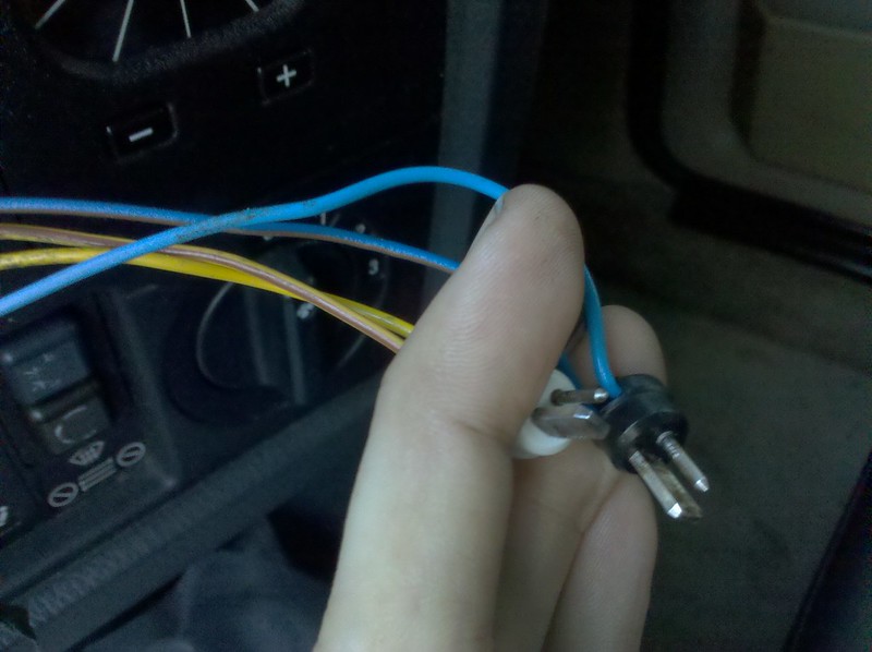
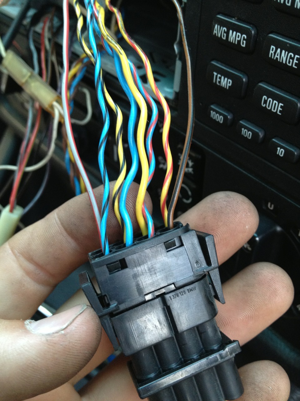
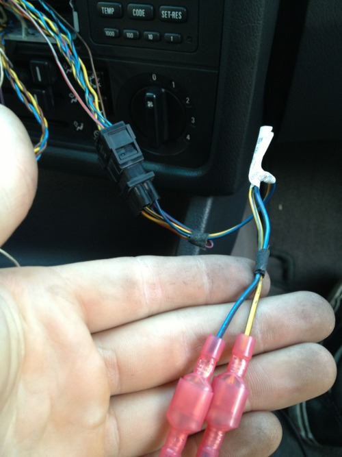
-Fader switch in the dash***
***Fader does NOT have twisted pairs along the wiring path AT ALL. Fader wires DO NOT change colors, there are NO additional wires in the bundle. I followed them all the way behind the speedo to make sure. There's only the 4 striped and 2 solid wires going to the fader switch.
Photos of my head unit, fader switch and wiring to the head unit:
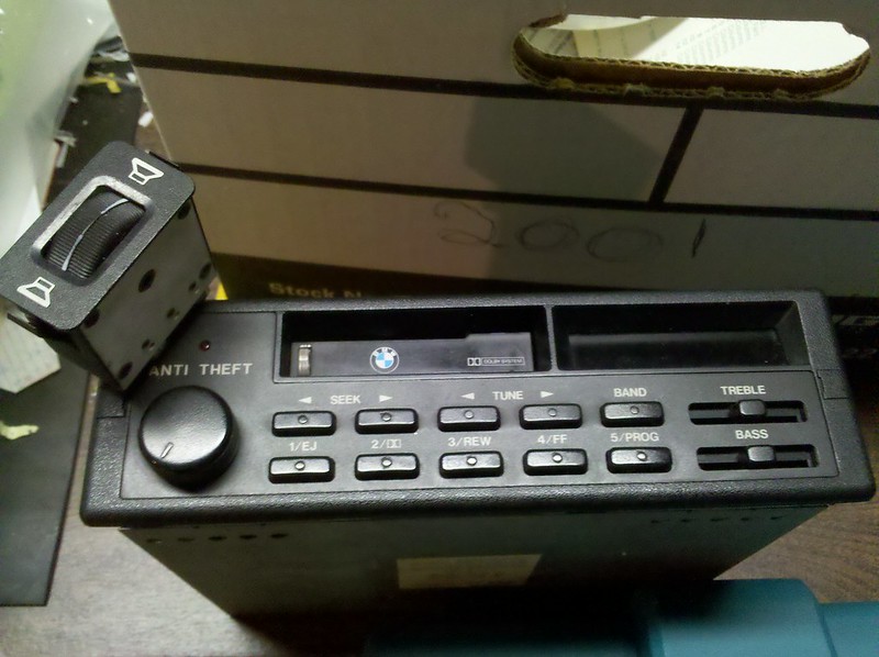
IMG_20130210_103441 by Spyke e36/e30, on Flickr

IMG_20130210_092643 by Spyke e36/e30, on Flickr

IMG_20130210_092814 by Spyke e36/e30, on Flickr
IMG_20130210_092929 by Spyke e36/e30, on Flickr
Got all my new radio wiring done, this might help Early model guys. I was super confused at how the OEM wiring was done, but once I had it all out the rewiring made perfect sense. I re-purposed all the OEM wire as it's in good shape, retained the previous wiring colors as to not confuse anyone else who MIGHT get the car after me and as mentioned in here very good quality high copper content.
I now have a permanent e36 female plug so that wiring will never have to be messed with again in the future, easy upgrades. This is for my 87 ETA, fader in dash, no amp in trunk, standard speakers. Wiring colors followed a fairly consistent pattern to my surprise. Here's what I did:
e30 ETA OEM wiring <> e36 female radio plug <> Metra 70-8590 plug
12v ignition/acc
Violet/Grey <> Violet/(White) <> Red
12v batt/constant
Red/Green <> Red/(White) <> Yellow
Ground
Brown <> Brown <> Black
Power antenna
(White) <> (White) <> Blue
Illumination
Red/Grey <> Red/Grey <> Orange
Right Front +
Blue/Red <> Blue/Red <> Grey
Right Front -
Blue/Brown <> Brown/Orange <> Grey/Black
Left Front +
Yellow/Red <> Yellow/Red <> (White)
Left Front -
Yellow/Brown <> Brown/Orange <> (White)/Black
Right Rear +
Blue/Black <> Blue/Black <> Violet
Right Rear -
Blue/Brown <> Brown/Orange <> Violet/Black
Left Rear +
Yellow/Black <> Yellow/Black <> Green
Left Rear -
Yellow/Brown <> Brown/Orange <> Green/Black
***The e36 female plug will have the speaker + and - as a twisted pair. I highly recommend connecting only ONE pair at a time to keep from getting confused, since all speaker negatives on the e36 plug have the same color wire.
PLEASE PLEASE PLEASE do yourself a favor and double-check the power/acc/illumination wire colors with a TEST LIGHT BEFORE making final connections. It's the only way to know for sure. Speaker wires are straight forward, but you're a moron if you don't test the important wires before starting.Last edited by Spyke; 05-18-2013, 11:00 PM.Comment
-
Alright, I don't know if this is the fader or what, but I'm having trouble figuring out what is what for each speaker/ground. All of the aftermarket headunit colors from your guide matched up, but I couldn't quite figure out the stock wire coloring. So I went based off of where they where hooked up on the stock deck, and tried splicing them accordingly to the new deck. I got sound, but not in all the speakers. I then found wires that were the correct colors as you described for the dash wires, but they weren't hooked directly to the head unit. If this is the fader, then your description makes sense, but... in that case I don't know where the grounds are for each speaker. I wanted to check in before I made the cuts to these wires and went too far. Help!
Comment
-
Alright I found out what a fader is and I don't have it. So, do I cut these wires off about this black harness/plugin, and splice those into there appropriate speaker according to your guide?Comment
-
Closing SOON!"LAST CHANCE FOR G.A.S." DEAL IS ON NOW
Luke AT germanaudiospecialties DOT com or text 425-761-6450, or for quickest answers, call me at the shop 360-669-0398
Thanks for 10 years of fun!Comment


Comment