Announcement

Collapse
No announcement yet.

MAP sensor hookup?

Collapse
X
 
  • Filter
  • Time
  • Show
Clear All
new posts

    MAP sensor hookup?

    Hey guys,

    I've had this idea floating in my mind for a long time..
    Not that i dont like the AFM or something, but i do not like it , lol :devil:

    So best way to replace it would be to use a MAP sensor.
    You can't directly connect it, the Motronic wont understand it.

    So my idea was to adopt the MAP sensor voltage to the corresponding AFM voltage, ie map the map ;D

    Basic scheme using Paint:


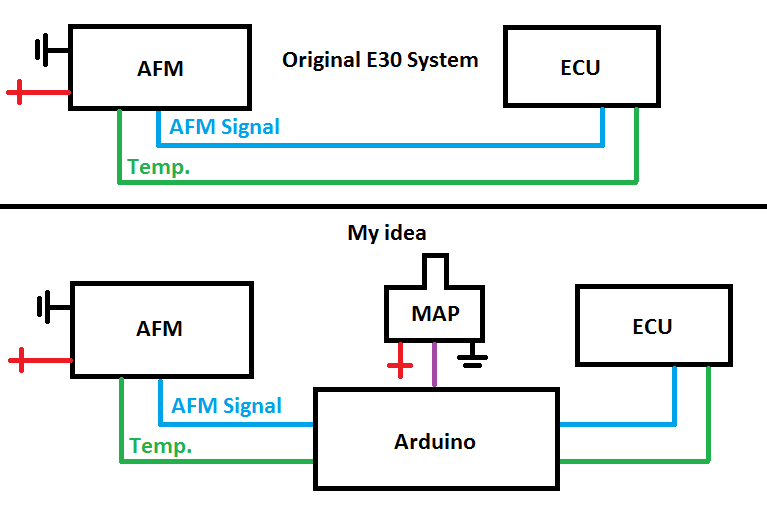
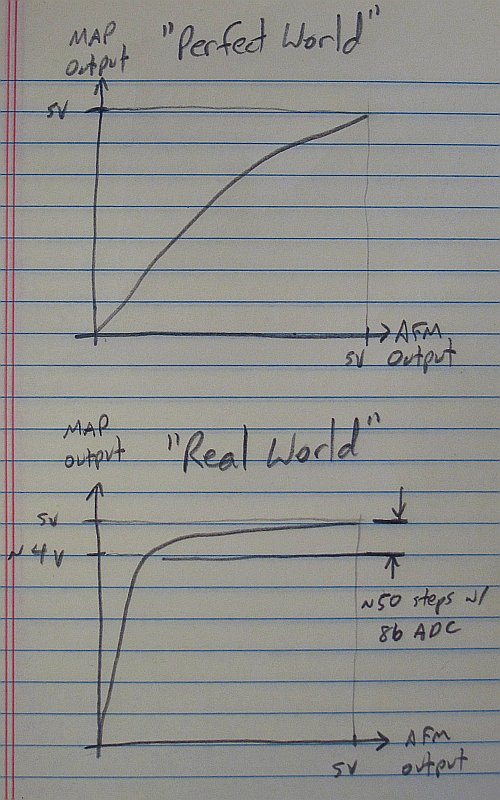
    At first i would connect the MAP sensor and leave the AFM connected, and drive around just logging the voltage data to the Arduino, ie at this AFM voltage we have this MAP voltage, and at that AFM voltage we have that MAP voltage.
    Basically just create a table of voltages across the whole 5v range.
    After collecting data for a few days/weeks i would know the range and could just unhook the AFM and only keep the MAP and Temp sensor connected, and would just use the MAP for the voltage output to DME, since i would have all the voltage table.

    This would act something like the UAFC from 14point7.
    And it could also be setup to correct the voltage going to the DME to give you more/less fuel.

    What are your thoughts on this?
    Do you have any suggestions?

    Thank you,
    Max.
    5-lug Kit | E36 & E46 Hub & Brake Adaptor for E30!
    Leave feedback about my transactions!
    sigpic

    #2
    why would you need to create a table of MAP voltages? all you have to do is look at the datasheet, it will tell you what the voltages are for a given load. essentially, 1kpa = 100% load.

    MAP and the AFM actually work in very similar ways; Motronic 1.x is basically a speed-density system already. you would need to alter the AFM curve to match the load/voltage output of the MAP sensor.

    I would talk to forced firebird about this, I think he's done it already. there's been some talk about it on E30tech in the past as well.
    Build thread

    Bimmerlabs

    Comment


      #3
      Just the guy i was wanting to reply :)

      Well ya, looking at the datasheet would work too, lol.
      So 0 BAR at the map sensor would be the same as AFM fully open, right?
      So it's just a linear curve..

      Also, on a side note, best place for a MAP sensor on an M40/M42? Drill new hole in the manifold or reuse some vacuum hose with a T fitting?

      Max.
      5-lug Kit | E36 & E46 Hub & Brake Adaptor for E30!
      Leave feedback about my transactions!
      sigpic

      Comment


        #4
        no, 0 bar would be full vacuum, IE the AFM is closed. 1 bar would be WOT/AFM opened.

        I would try to put it in the plenum portion of the manifold.
        Build thread

        Bimmerlabs

        Comment


          #5
          Got it, thanks :)

          Also, will barometric pressure affect the MAP sensor? Should i somehow calibrate it on turn on just like all new cars? :)
          5-lug Kit | E36 & E46 Hub & Brake Adaptor for E30!
          Leave feedback about my transactions!
          sigpic

          Comment


            #6
            theoretically yes, but in reality not really. I've run both with barometric correction and without and there's not really any difference.

            there won't be any calibration other than the curve unless you can write assembly code..
            Build thread

            Bimmerlabs

            Comment


              #7
              Super, then thays easy :)
              Love combining the hobby (E30) with job (Programmer)

              Thanks for the help mate :)
              Maybe theres some specific MAP sensor i should be looking for? :)
              Its hard getting GM sensors here, so im better some Motorolla or ther brands i can get in a electric shop :)

              Max.
              5-lug Kit | E36 & E46 Hub & Brake Adaptor for E30!
              Leave feedback about my transactions!
              sigpic

              Comment


                #8
                Hey guys,

                Quick update, got all the parts on my hands, but had another idea (lol)
                If i an go to a MAP sensor that easy, that means i can go to a variable TPS the same way, since it will show almost the same data as a MAP sensor will.

                Am i right?
                5-lug Kit | E36 & E46 Hub & Brake Adaptor for E30!
                Leave feedback about my transactions!
                sigpic

                Comment


                  #9
                  No, they aren't at all the same.
                  Build thread

                  Bimmerlabs

                  Comment


                    #10
                    Well, my logic was that when the throttle is closed - we have vacuum, so map sensor would show the same with closed throttle, fully open - map sensor would show outside pressure, i could just "map" it to the right values on 0-100% and be at the same level, no?
                    5-lug Kit | E36 & E46 Hub & Brake Adaptor for E30!
                    Leave feedback about my transactions!
                    sigpic

                    Comment


                      #11
                      No.. otherwise, alpha-n wouldn't exist. Load and vacuum don't correlate directly with throttle position.
                      Build thread

                      Bimmerlabs

                      Comment


                        #12
                        There are a couple of things that you will need to do to make this cooperate with the Motronic, especially on a 4 cylinder.

                        1) There is an air temp thermistor built into the AFM. The ECU needs this input in order to convert the volumetric air flow rate into a mass flow rate for the load calculation. It is also important because the ECU will retard ignition timing when the incoming air is above a certain temperature in order to avoid detonation. You have 2 options: harvest the thermistor out of the AFM, or buy one with similar temp-resistance characteristics. I can recommend a $0.40 Digikey part that is almost an exact match.

                        2) The MAP sensor responds MUCH more quickly than the AFM and will be able to resolve individual intake strokes. This is particularly pronounced on 4 cylinders since there is no significant intake overlap. If you were to look at the voltage output of the AFM and MAP at WOT around 2800RPM on an M42, you would see a fairly smooth signal coming out of the AFM, and the MAP output would look like a big ~90Hz sine wave with up to 3V peak-peak amplitude (depends on the sensor). This is a problem for the Motronic since, as far as I have been able to figure from my work on a MAF conversion, it reads the AFM voltage 100 times per second at MOST. I am not sure how much you know about Nyquist's Sampling Theorem, but basically you need to measure a signal at 2x (absolute minimum) the frequency of the highest frequency present in that signal or you get invalid readings (aliasing).

                        So, you have a couple of options to low-pass filter (LPF) the MAP-to-AFM output.
                        a) Develop a digital filter and apply it to the MAP signal in the Arduino software. The ARM microcontroller in there is not really ideal for high performance digital signal processing (DSP) applications, but you can get by with one of a few IIR type filters. A double moving average of 16 samples at 2kHz would probably be enough to get by.

                        Your other option, b) is to use an analog filter on the converter output which will perform about the same as an IIR digital filter, although it will add cost since you need to buy tight tolerance components to make your filter perform reasonably well.

                        Even with option (a) you will need an anti-aliasing LPF on the MAP signal going to the Arduino. Sorry about the length of item #2 here, but it is going to be a vital part of implementing this well. In either case, you can expect to add in the neighborhood of 30ms of delay to the signal in order to tame the signal at the M42's intake resonance points, which is still quite a bit better than the AFM's response speed. The stock airbox makes the resonance pulses a lot worse than, say, a cone air filter, but I still recommend the stock box since it keeps hot air out of the intake.


                        There are a few practical things you should know too.

                        - One, the AFM causes you to lose precisely ZERO horsepower on an internally stock M42. Even on my strung out 2.1L M42 a MAF nets at MOST 5bhp. The AFM just is not restrictive because it is properly sized for the M42. In the case of the M20, the stock AFM opening is the same size as the M42's, which is why the M30 AFM swap is popular and actually improves air flow for the M20. With that said, I highly encourage you to play with this because you will probably learn a ton about electronics and embedded systems. It is good fun. Just don't go into it expecting to get on a dyno and gain power. In fact, you may well lose a little power as you deal with the LPF issues relating to a "fast" sensor like the MAP talking to a DME expecting a "slow" signal from the AFM. It's all part of the process though.

                        - Two, you are going to find that you will see the manifold pressure get close to atmospheric for relatively small (maybe 50-60%) throttle openings, regardless of RPM. So, this leaves a pretty small voltage range from the MAP with which to use for correlating to a pretty large range from the AFM. I assume that the ADC on the Arduino is an 8 bit one, which is probably barely enough to scrape by with. You should think about using a 10 or 12 bit ADC really. You'll get a feel for it once you start doing some logging. See the crappy sketch image at the end of this post for some clarification of what I mean here. EDIT: Looks like most Arduino's have a 10b ADC onboard, so you might be OK here. 12b or better is still recommended though.

                        - Three, if you expect to stay NA on this engine, use the lowest pressure MAP sensor that you can get by with (2BAR maximum, something like 1.2BAR would be better). You want the maximum sensor resolution over your operating range that you can get because of the stuff I mentioned in the previous item.

                        If you want some support with the analog / EE aspects of this let me know. I can hook you up with some fairly simple filter designs, which you will need to keep the signals clean no matter what. You need to be especially careful about putting any sort of resistive elements in series or parallel with the AFM output because the sensor itself is resistive and the signal will get messed up if it goes into any sort of low-impedance node. Basically, the AFM signal needs to go into an opamp buffer stage before any filtering occurs.

                        Last edited by bmwman91; 04-11-2015, 03:20 PM.

                        Transaction Feedback: LINK

                        Comment


                          #13
                          Oh and 2 other things to tack on to the end.

                          Four, if your car uses an O2 sensor then you will not really be able to use this to mess with the mixture lean/rich point. The DME will use the O2 sensor to correct the fuel maps back to stoichiometric. If you skew the air flow signal enough, you will just get a Check Engine light.

                          Five, the relationship of volume air flow rate to manifold pressure is exactly dependent on the volumetric efficiency curve of the engine. ANY physical change that you make to anything in the intake will mean that you need to strap the AFM back on and re-calibrate your conversion curve. Even switching from the stock air filter to a cone air filter might be enough to mess up the calibration a little. This is actually why MAF sensors essentially dominate the market with newer cars...they directly measure the mass flow rate of the incoming air and account for air temperature and pressure without needing any calibration to whatever is downstream from them. There are other challenges to implementing a MAF, but that is a different discussion.

                          Transaction Feedback: LINK

                          Comment


                            #14
                            Oh wow mate, nice. Really did not expect a reply like that. Lots of useful info.

                            Ok, il put my plan down here, at the moment i'm starting to get all the parts i ordered, they are:

                            - Arduino Nano V3 (No onboard DAC)
                            - LM7805 5V Voltage Regulator
                            - MCP4725 I2C DAC
                            - Motorolla MPX4250 2.5 Bar MAP Sensor
                            - Scrap AFM connectors and wiring plug
                            - M20 AFM Temp sensor

                            At first i am just going to hookup the Arduino to log the sensor values of the MAP and AFM, so i can get a basic idea of what i am working with. So it will just be a simple data logger for some time.

                            It will read the MAP value and AFM value and write it on an SD card. Need as much data as i can to make a good table, so it might stay logging there for a month, dont know yet.

                            Might try and create some small program to test some algorithms to get the response time as close as possible to the AFM one.

                            The I2C DAC is going to be used as a 0-5v output, since the Arduino cant output analog voltage, only PWM (Didn't want to go RC Filter way, want to keep it all digital, also no ripple this way). Also why i want to use LM7805 voltage regulator, since i dont know how stable Motronic's 5v is, lol.

                            MAP sensor is 2.5 Bar, it will do for now, since i might go Turbo in the future.

                            Might put a switch somewhere in the car so i can switch AFM <> MAP sensors if something goes wrong.

                            So there, dont know how much samples i am going to use at the moment, but i will figure it out once i start working with it.

                            EDIT:

                            Not trying to get any HP gains on this, just love to mess with electronics and learn something new :)

                            Max.
                            5-lug Kit | E36 & E46 Hub & Brake Adaptor for E30!
                            Leave feedback about my transactions!
                            sigpic

                            Comment


                              #15
                              I figure I should pass on some knowledge since I spent the last ~10 years messing around with MAF conversions and engine controls. Glad it helps.

                              Here are a few thoughts based on your stated plans:
                              - The M20 IAT thermistor won't work directly. It has a different NTC curve than the M42's. You could try to convert the signal, although IMO it is more trouble than it is worth. I forget the value of the series pull-up resistor on the the Motronic 1.7 PCB, but I believe it is 1kOhm, so consider that if you try to emulate the M42 IAT thermistor with a DAC. You'll also need to take some reasonably accurate resistance measurements over a range of temperatures and plug those into the Steinhart-Hart equation and then stuff that into a voltage divider calculation to determine the temp-vs-voltage curve for this.

                              - You should have a MINIMUM sampling rate of 500Hz for this, because of the MAP sensor. At 7200RPM, you will have a ~240Hz signal of (some) amplitude. Personally, I like to sample at at least 10x the max frequency of interest to get a decent picture, so think about logging at 2.5kHz or faster.

                              - One benefit is that you can improve the response speed of things. The AFM is pretty slow, and there is no problem with having the air flow signal respond more quickly to a big change, like flooring the gas pedal. The frequency content of a WOT event like that is only up to maybe 10Hz, which the DME can handle fine.

                              - Glad to hear that you are doing this for fun. It's the best reason to do things!

                              - You'll need input buffers for signals going to the ADC, and you will need output buffers after the DAC. This is both to filter out high frequency noise, and to protect the expensive microcontroller. It is also basically mandatory for the AFM and IAT signals since they are resistive and very sensitive to other things in the signal path.

                              Transaction Feedback: LINK

                              Comment

                              Working...
                              X