

Does this fit the 6 button obc as well?
Sent from my SM-G930V using Tapatalk
-
So did anyone successfully order one of these and get it shipped to the US? Because I am so ordering one.
UPDATE: Got one, took a couple weeks for delivery but it's installed and working great in my 6-button OBC
Last edited by muppetman342; 07-09-2018, 03:06 PM.Leave a comment:
-
-
-
hmm, considering getting one as a backup.."just in case".
IIRC, the screen has never been replaced on mine. Is this something that'll ultimately go on me? kinda like SI board batteries?Leave a comment:
-
DAMN! That's great! I wish I had known about it before I swapped mine for a used unit off of ebay.Leave a comment:
-
LCD replacement
You really do not believe it but you can buy new screen from Germany shop www.partworks.de .
Just swapped my OBC screen and it is really working!


Leave a comment:
-
For the cost of a custom LCD unit in a small quantity, you could probably buy a new M3. The design and tooling to fab an LCD part, even one as seemingly simple as this, have significant cost associated with them. Then again, maybe you could find a factory on Alibaba to do it, but I would be surprised.
Finding a generic LCD, either 8 digit or a dot matrix, and then driving it with an Arduino or PIC which intercepts the mainboard's signals seems more likely. IIRC, the protocol that the existing controller uses involves a clock and 160 bits of data with each bit corresponding to one of the individual display segments. I may have the logic analyzer captures at home somewhere. The other 3 pins are 5V, ground and a 256Hz square wave which I believe is used to de-bias the charge on the LCD segments so that charge build-up does not cause the segments to all become opaque, but this is not likely to be needed if you go with a new LCD module since it will either be built in to the controller or just not necessary since we have 30+ years of technological advances.Leave a comment:
-
For the cost of a custom LCD unit in a small quantity, you could probably buy a new M3. The design and tooling to fab an LCD part, even one as seemingly simple as this, have significant cost associated with them. Then again, maybe you could find a factory on Alibaba to do it, but I would be surprised.
Finding a genericLCD, either 8 digit or a dot matrix, and then driving it with an Arduino or PIC which intercepts the mainboard's signals seems more likely. IIRC, the protocol that the existing controller uses involves a clock and 160 bits of data with each bit corresponding to one of the individual display segments. I may have the logic analyzer captures at home somewhere. The other 3 pins are 5V, ground and a 256Hz square wave which I believe is used to de-bias the charge on the LCD segments so that charge build-up does not cause the segments to all become opaque, but this is not likely to be needed if you go with a new LCD module since it will either be built in to the controller or just not necessary since we have 30+ years of technological advances.Leave a comment:
-
-
My OBC doesn't work. Again....
I don't even want to bother replacing it with a used replacement because I'm convinced that given the amount of electronics in these things, the replacement would be on borrowed time.
I will throw the challenge out: Someone design a retro-OBC that uses form-factor of the old one, but with a PIC that replaces the 30+ year old electronics, and an OLED display that can have oil temperatures and such.
Here's an example: https://www.sparkfun.com/products/11677
If we could have a 2018 version of the OBC, what features would it have? I couldn't really care about average speed and such. Personally, I would make a CANBUS repeater for parameters on my Megasquirt.Attached FilesLast edited by hoveringuy; 12-18-2017, 07:05 AM.Leave a comment:
-
-
That display is entirely custom, you will not find an off the shelf solution. Best you could do is salvage a known broken OBC with a good LCD.
An Arduino is overkill and quite large, an 8 bit processor could be used to drive a modern LCD display, interpreting and converting the signals from OBC. A PIC microprocessor would work well, they can accept higher voltages too.Leave a comment:
-
You wont fix the lcd. I had a bit of a google around. The lcd looks custom for the job. Big numbers and small numbers. Ive got no idea what functions are on it, but replacing it with an aduino and a gineric lcd would be a fun project. All doable (ive played with arduinos a fair bit). But youd have to be pretty keen to go to that much effort.Leave a comment:
-
bmwman91 - yea I took apart the OBC today and took some pictures along the way. It looks like the OBC was somewhat designed to have replacement parts. Atleast the We can separate the problematic part. But like you said, who knows if there is a replacement part on the market. That's what I'm looking for. Someone to produce a replacement screen assembly!
The OBC comes apart at this seam, but you must remove the two screws on the back of the OBC.
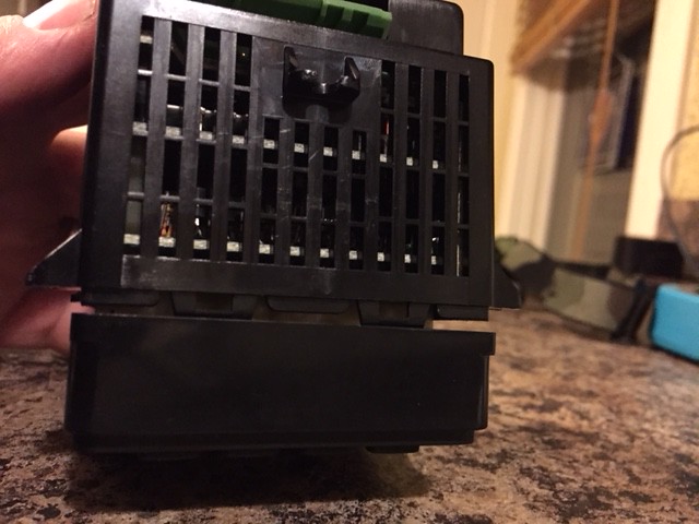
The back cover comes off around the green plug. This is what you're left with once you pull the back cover off:
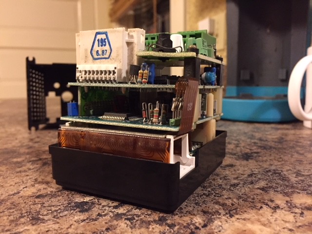
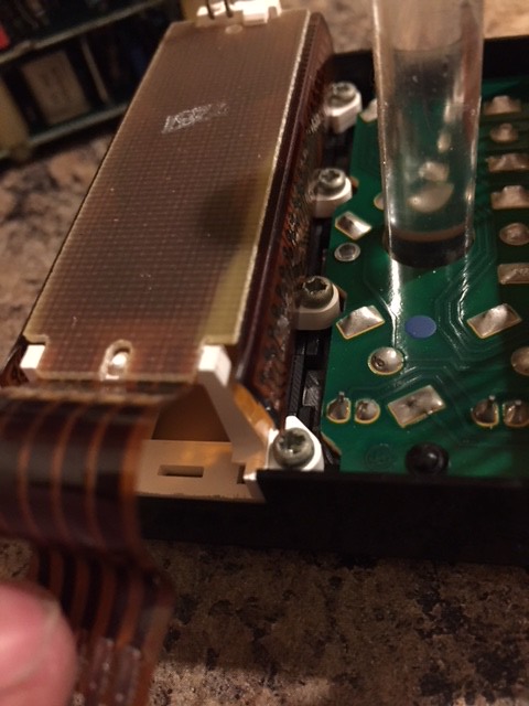
Next up, preparation to separate the faceplate from the motherboard. You can use needle nose to pull these from the posts:
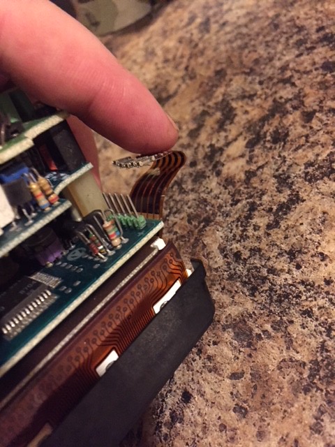
This part sucks, I actually cut my finger pulling the motherboard off of the faceplate. You have to pull pretty hard, and wiggle back and forth to get them to separate.
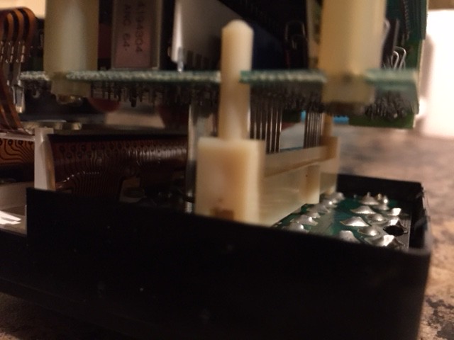
Now that the motherboard has been separated, there are 7 screws that hold the screen assembly onto the faceplate. I used a small electronic/jewelry philips to remove them.
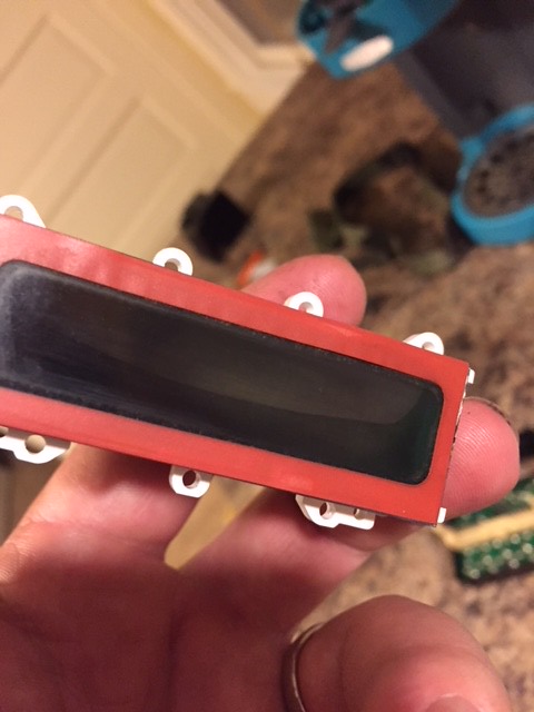
Damn you broken screen...
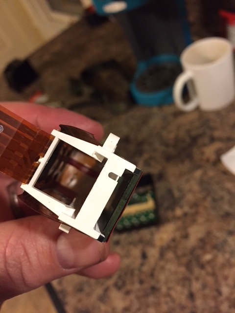
two filters go between the screen back and the backlight area:
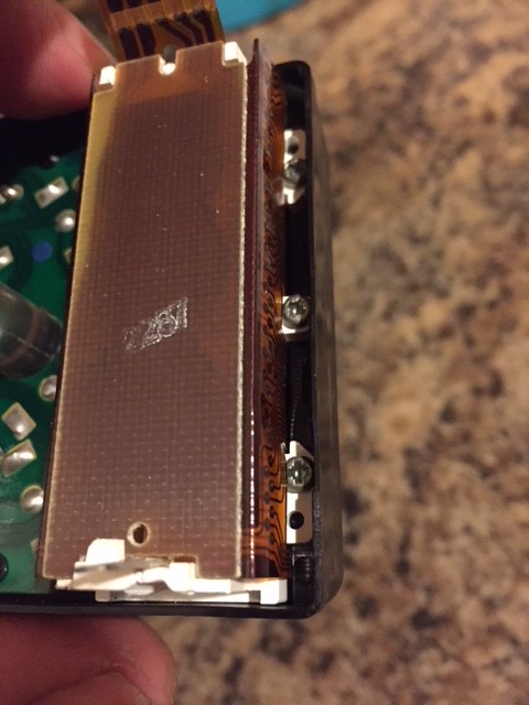
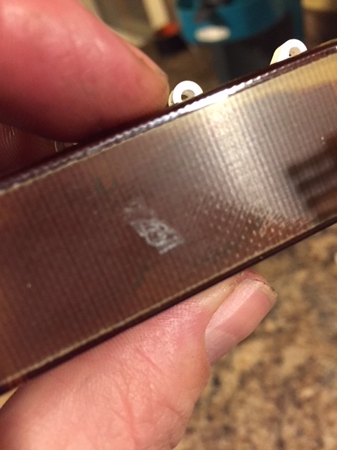
I can't really make it out, but there's a stamp on the back of the screen assembly:
Now who can I ship this bad bitch to who can figure out how to reproduce one?Leave a comment:


Leave a comment: