
Reading a few threads, it seems there is some confusion on how to read the ETM. I'm going to go through a diagram and explain what some of the symbols and numbers mean. Hopefully it helps!
Here is a typical power window diagram for an E30.
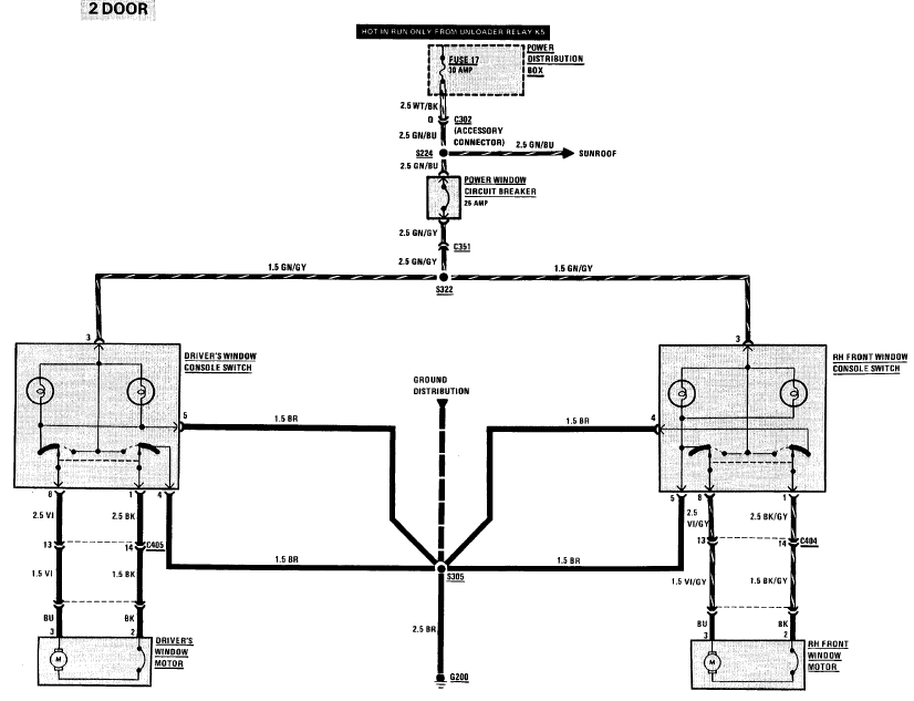
It looks pretty straightforward, but there is a lot more information presented than you might suspect at first glance. Lets start with the power source.

Pictured here is a description of where the circuit begins to be dedicated to the power windows. This is done so, because though the circuit naturally begins at the battery, there are many connections to the rest of the electrical system as well and showing them all would make for a very cluttered print. Therefore, the fuse is a good place to start considering each circuit "individual".
We can see we are dealing with fuse 17, which has a rating of 30 amps. We can also see in the diagram that fuse 17 is "hot in run only from unloader relay K5" This means our windows will only receive power via fuse 17 when the car is in run, and relay K5 is switched on.
The fuse is shown in a shaded box with a dashed border labeled "Power distribution box" which is the underhood fusebox on an E30. The dashed border is important in that it tells us that the entire component is not shown on this diagram, which we all know that there is more in that fusebox that just fuse 17. Only that part of the distribution box is shown as it is relevant to the print we are looking at.
----------
Next is a little bit of harness coming from the fusebox and into the center console.
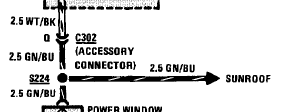
There is a wealth of information about the circuit in this small space, but it isn't the easiest to understand at first glance.
First thing you see is "2.5 WT/BK" next to a section of wire. This tells you the wire gauge in square millimeters and the color of the wire. There is a handy chart for decoding the different wire color abbreviations and converting the wire gauge from sqmm to the more familiar in the US AWG standard. "2.5 WT/BK" means that the wire coming from the power distribution box is a 12 gauge white wire with a black stripe.
Next the wire goes into a little chevron labeled "Q" and "C302". This means that the wire is located in a connector (hence the "C" designation), specifically connector number 302. In C302, the wire we are interested in is located at pin "Q". The ETM shows us where to find C302 (and most other connectors/components/splices/grounds), as well as which pin is "Q". I will get into that later.
Coming out of C302, pin Q, you now have a 12 gauge green wire with a blue stripe. It continues on to a dot labeled "S224". "S224" is a splice (hence the "S" designation) named 224. It's (rough) location in the car is also shown elsewhere in the ETM. At S224, three wires are connected. Two are part of the circuit we are following, and one goes off to an arrow labeled "Sunroof". That means that the part of the circuit shown after the splice is found on another page of the ETM, again not shown on the same page as the windows for clarity. They include that so that you know everything that goes on in the harness to the windows though, in case you end up having a rotted splice or something, you will know that there is one in the circuit, where it is in the car, and what is connected to it.
It is also a helpful diagnostic tool because if you were troubleshooting inoperative power windows, and your sunroof worked fine, you would know that the circuit is intact and functional at least until that splice. Good for narrowing down where to concentrate your efforts.
----------
Next up is the circuit breaker, the mystery rectangular black button on the dash.

The wire from the splice enters the power window circuit breaker, which is rated for 25A. Fuses are designated by the "S" shaped wire between two posts, and circuit breakers are shown with the "C" shaped wire. The power window circuit breaker has a solid border, meaning that it is shown in its entirety.
----------
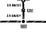
Coming out of the circuit breaker, you have a 12 gauge green wire with a gray stripe as shown by the "2.5 GN/GY". It enters connector "C351" which does not have a pin designation. That means its likely a single pin connector. From there its off to Splice "S322"
----------
From S322 the circuit goes to each window switch, one of which is shown here.
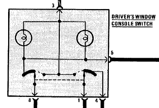
This is the diagram of the window switch in it's entirety as indicated by the solid border. The power comes from S322 into pin 3. From there, the switch has an internal splice that branches off to two circles with looped wire in them and something that looks like an upside down "T". The circles are representing light bulbs, and these two are for the backlight illumination of the switch. Since they are directly connected to window power via terminal 3, and ground via terminal 5 (more on the other terminals in a bit) they should be illuminated anytime the windows have power, and at least a partial ground (as there is another ground terminal on the switch).
Looking at the main diagram for the windows, you can see terminal 5 and terminal 4 eventually connect together and then to ground. Terminal 5 has splices internal to the switch connecting it to both lights and something represented by a curved black bar on the diagram. Terminal 4 connects to the other curved black bar.
The curved black bars, upside down "T", and the arrows attached to posts that are currently pointing at the curved black bars are all what represent the switch contacts. The arrows represent movable contacts. They are joined by a dashed line, which means that the two contacts move in tandem, either to the left or the right of the diagram. Typically, any time a switch is drawn in a diagram, it is drawn in the "at rest" position. In this case, when the arrows are straight up, the button is not pressed. When they would point to the left or right is when you are pushing up or down.
The curved black bar represents a continuous contact in the switch. In the "at rest" position, both arrows are connected to this contact. When the arrows move to the left, the one on the left side (connected to terminal 8 ) maintains contact with the black bar, while the arrow on the right side (connected to terminal 1) breaks contact with the black bar as it moves towards the upside down "T". The dots at the ends of the "T" are also contacts, and the arrow on the right side will make contact with the "T" as the button your pushing ends its travel.
This keeps terminal 8 connected to ground, and disconnects the ground from terminal 1 and connects it to the power from terminal 3. When you move the arrows in the other direction by pushing the other button, the opposite occurs, terminal 1 stays grounded, and terminal 8 gets power.
----------
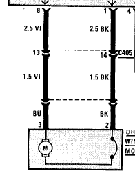
Terminal 1 and 8 exit the switch and are connected to a 12 gauge violet and a 12 gauge black wire. They both are shown going to the chevron symbols (which mean it is a connector) but the two are connected by a dashed line.
This dashed line means that they are both located in the same connector, C405. The violet wire is located at terminal 13 of C405, and the black wire is at terminal 14.
Coming out of C405, both wires remain the same color, but step down in wire gauge as indicated by the "1.5". Now the violet and black wires are 14 gauge instead of 12.
From there they connect to the window motor pigtail (It's connector is not given a name as it is part of the window motor assembly) Inside the window motor assembly (represented in its entirety here, as indicated by the solid border) there is the actual motor itself, and yet another circuit breaker.
Both motor leads usually have a ground connection, but when you want to move the window, either one wire or the other will switch to positive as we saw from our switch.
----------
Now for the grounds
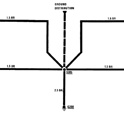
Here we see the wires from both window switches ground terminals all join together at splice S305. Also connected to S305 is a dashed wire coming from an arrow labeled "ground distribution", and a wire leading to "G200".
The "G" in "G200" stands for ground, and the "200" is the name of the specific ground point. The dashed wire indicates that there are more connections to this ground circuit than are listed here, and that they are found in the ground distribution section of the ETM (right after the power distribution section).
Now, where in the car is G200? The ETM has a "Component location chart" towards the back, usually starting on page 9000-0. Flipping through that, you will find G200 (the one I am using had it on page 9000-5) along with a description of where its located (mine said "Under LH side of dash, above brake pedal") along with another page number. If the description still left you wondering, the page number takes you to a page that has an actual picture of the ground in the car. This applies to splices, connectors, grounds and components, each can be located this way.
Also in the back, there is a section called " Connector views". These are end-on drawings of the connectors with each pin labeled, so you know exactly which pin is which when paired up with the information in the diagrams.
That info should hopefully get you started with the ETM, and on the way to understanding your car and its electrical systems a little bit better!
Here is a typical power window diagram for an E30.
It looks pretty straightforward, but there is a lot more information presented than you might suspect at first glance. Lets start with the power source.
Pictured here is a description of where the circuit begins to be dedicated to the power windows. This is done so, because though the circuit naturally begins at the battery, there are many connections to the rest of the electrical system as well and showing them all would make for a very cluttered print. Therefore, the fuse is a good place to start considering each circuit "individual".
We can see we are dealing with fuse 17, which has a rating of 30 amps. We can also see in the diagram that fuse 17 is "hot in run only from unloader relay K5" This means our windows will only receive power via fuse 17 when the car is in run, and relay K5 is switched on.
The fuse is shown in a shaded box with a dashed border labeled "Power distribution box" which is the underhood fusebox on an E30. The dashed border is important in that it tells us that the entire component is not shown on this diagram, which we all know that there is more in that fusebox that just fuse 17. Only that part of the distribution box is shown as it is relevant to the print we are looking at.
----------
Next is a little bit of harness coming from the fusebox and into the center console.
There is a wealth of information about the circuit in this small space, but it isn't the easiest to understand at first glance.
First thing you see is "2.5 WT/BK" next to a section of wire. This tells you the wire gauge in square millimeters and the color of the wire. There is a handy chart for decoding the different wire color abbreviations and converting the wire gauge from sqmm to the more familiar in the US AWG standard. "2.5 WT/BK" means that the wire coming from the power distribution box is a 12 gauge white wire with a black stripe.
Next the wire goes into a little chevron labeled "Q" and "C302". This means that the wire is located in a connector (hence the "C" designation), specifically connector number 302. In C302, the wire we are interested in is located at pin "Q". The ETM shows us where to find C302 (and most other connectors/components/splices/grounds), as well as which pin is "Q". I will get into that later.
Coming out of C302, pin Q, you now have a 12 gauge green wire with a blue stripe. It continues on to a dot labeled "S224". "S224" is a splice (hence the "S" designation) named 224. It's (rough) location in the car is also shown elsewhere in the ETM. At S224, three wires are connected. Two are part of the circuit we are following, and one goes off to an arrow labeled "Sunroof". That means that the part of the circuit shown after the splice is found on another page of the ETM, again not shown on the same page as the windows for clarity. They include that so that you know everything that goes on in the harness to the windows though, in case you end up having a rotted splice or something, you will know that there is one in the circuit, where it is in the car, and what is connected to it.
It is also a helpful diagnostic tool because if you were troubleshooting inoperative power windows, and your sunroof worked fine, you would know that the circuit is intact and functional at least until that splice. Good for narrowing down where to concentrate your efforts.
----------
Next up is the circuit breaker, the mystery rectangular black button on the dash.
The wire from the splice enters the power window circuit breaker, which is rated for 25A. Fuses are designated by the "S" shaped wire between two posts, and circuit breakers are shown with the "C" shaped wire. The power window circuit breaker has a solid border, meaning that it is shown in its entirety.
----------
Coming out of the circuit breaker, you have a 12 gauge green wire with a gray stripe as shown by the "2.5 GN/GY". It enters connector "C351" which does not have a pin designation. That means its likely a single pin connector. From there its off to Splice "S322"
----------
From S322 the circuit goes to each window switch, one of which is shown here.
This is the diagram of the window switch in it's entirety as indicated by the solid border. The power comes from S322 into pin 3. From there, the switch has an internal splice that branches off to two circles with looped wire in them and something that looks like an upside down "T". The circles are representing light bulbs, and these two are for the backlight illumination of the switch. Since they are directly connected to window power via terminal 3, and ground via terminal 5 (more on the other terminals in a bit) they should be illuminated anytime the windows have power, and at least a partial ground (as there is another ground terminal on the switch).
Looking at the main diagram for the windows, you can see terminal 5 and terminal 4 eventually connect together and then to ground. Terminal 5 has splices internal to the switch connecting it to both lights and something represented by a curved black bar on the diagram. Terminal 4 connects to the other curved black bar.
The curved black bars, upside down "T", and the arrows attached to posts that are currently pointing at the curved black bars are all what represent the switch contacts. The arrows represent movable contacts. They are joined by a dashed line, which means that the two contacts move in tandem, either to the left or the right of the diagram. Typically, any time a switch is drawn in a diagram, it is drawn in the "at rest" position. In this case, when the arrows are straight up, the button is not pressed. When they would point to the left or right is when you are pushing up or down.
The curved black bar represents a continuous contact in the switch. In the "at rest" position, both arrows are connected to this contact. When the arrows move to the left, the one on the left side (connected to terminal 8 ) maintains contact with the black bar, while the arrow on the right side (connected to terminal 1) breaks contact with the black bar as it moves towards the upside down "T". The dots at the ends of the "T" are also contacts, and the arrow on the right side will make contact with the "T" as the button your pushing ends its travel.
This keeps terminal 8 connected to ground, and disconnects the ground from terminal 1 and connects it to the power from terminal 3. When you move the arrows in the other direction by pushing the other button, the opposite occurs, terminal 1 stays grounded, and terminal 8 gets power.
----------
Terminal 1 and 8 exit the switch and are connected to a 12 gauge violet and a 12 gauge black wire. They both are shown going to the chevron symbols (which mean it is a connector) but the two are connected by a dashed line.
This dashed line means that they are both located in the same connector, C405. The violet wire is located at terminal 13 of C405, and the black wire is at terminal 14.
Coming out of C405, both wires remain the same color, but step down in wire gauge as indicated by the "1.5". Now the violet and black wires are 14 gauge instead of 12.
From there they connect to the window motor pigtail (It's connector is not given a name as it is part of the window motor assembly) Inside the window motor assembly (represented in its entirety here, as indicated by the solid border) there is the actual motor itself, and yet another circuit breaker.
Both motor leads usually have a ground connection, but when you want to move the window, either one wire or the other will switch to positive as we saw from our switch.
----------
Now for the grounds
Here we see the wires from both window switches ground terminals all join together at splice S305. Also connected to S305 is a dashed wire coming from an arrow labeled "ground distribution", and a wire leading to "G200".
The "G" in "G200" stands for ground, and the "200" is the name of the specific ground point. The dashed wire indicates that there are more connections to this ground circuit than are listed here, and that they are found in the ground distribution section of the ETM (right after the power distribution section).
Now, where in the car is G200? The ETM has a "Component location chart" towards the back, usually starting on page 9000-0. Flipping through that, you will find G200 (the one I am using had it on page 9000-5) along with a description of where its located (mine said "Under LH side of dash, above brake pedal") along with another page number. If the description still left you wondering, the page number takes you to a page that has an actual picture of the ground in the car. This applies to splices, connectors, grounds and components, each can be located this way.
Also in the back, there is a section called " Connector views". These are end-on drawings of the connectors with each pin labeled, so you know exactly which pin is which when paired up with the information in the diagrams.
That info should hopefully get you started with the ETM, and on the way to understanding your car and its electrical systems a little bit better!
Attached Files


Comment