-
:puppy:
So I made both outputs for wideband.
Brown went to the gauge, and Yellow to signal o2/MS (not that the wire to MS matters because I should still get an AFR reading on my gauge regardless, right?)
And...... nothing. Same thing. Pegged to 22.2 AFR on idle.
If I blip throttle it hits 7.4, then back to 22.2 AFR.


1991 325iS turbo

Comment
-
I would have to go back and look but I thought I remembered that it would read good on the gauge and not in TS?
And does TS show the same now?
I would get it working right with MS disconnected, it sounds like it is behaving like you have it set for NB when it goes from one extreme to the otherComment
-
It would read good on TS, but not the gauge back when I introduced the problem to you.
It used to read wonky on TS, but that went away after I grounded everything to the same ground (ECU shock tower).
On the LC1 programmer, I set the Analog 1 tab to:
0v = 7.35 AFR
5v = 22.39 AFR
Analog 2:
0v = 7.35 AFR
5v = 22.39 AFR
Then hit [Program].
I exited the programmer and reopened it to make sure it was saved and such.
I've connected my Narrowband to the gauge before and it pegs at 7.4 rather than 22.2 AFR.
1991 325iS turbo
Comment
-
I guess at this point give innovate a call. They helped me diagnose my lc-1 issue.Comment
-
Sorry for my late reply. I'm pretty urged to get this fixed.
I have read and re-read this along with many other write-ups!
I have the white analog ground grounded at the ECU ground/shock tower. I hope you weren't mistaking the white wire that comes out of the AFR gauge as an analog ground? The factory grounds in my o2 harness didn't work well for me (and many other people), hence why I grounded everything at the shock tower/ECU ground.
I did just that and nothing. ):
I need to make the time to phone-in Innovative. I might buy another o2 wideband replacement sensor from Autozone to test if they have a returnable return policy.
I'll update as I go.
1991 325iS turbo
Comment
-
UPDATE: Fixed.
Embarrassed to say that all I needed was a new sensor and my old new one (yes, brand new) was just fouled some how.
So for anyone who is wondering how to connect these to use with megasquirt to only have 1 o2, my wiring was correct from the get-go.
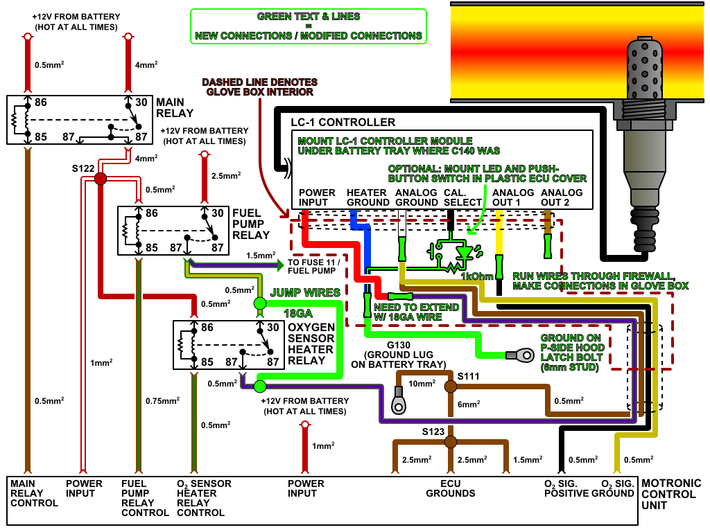
[LC-1 wire]
1. RED - - - - - - - - -12v switched - - - - - - - - - - Defroster switch (or any other convenient 12v switched)
2. BLUE - - - - - - - - Heater ground - - - - - - - - - ECU shock tower ground
3. WHITE - - - - - - - System ground - - - - - - - - -ECU shock tower ground
4. BLACK - - - - - - - Calibration wire - - - - - - - - -ECU shock tower ground
5. YELLOW - - - - - - Analog 1 (narrowband) - - - - Capped off
6. BROWN - - - - - - -Anolog 2 (wideband) - - - - - Signal wire on the stock o2 wiring (black wire of the 4) AND AFR gauge signal wire (white)
1991 325iS turbo
Comment


Comment