Announcement

Collapse
No announcement yet.

E30 M42 to Motronic 1.7.3 Conversion Project

Collapse
X
 
  • Filter
  • Time
  • Show
Clear All
new posts

    E30 M42 to Motronic 1.7.3 Conversion Project

    EDIT 8-Feb-2018: Dropbox link to project-related files and images.
    General Info: https://www.dropbox.com/sh/70yvbe8f8..._Zt4JMGNa?dl=0
    --------------------------

    Continuing from the original / more general thread:


    Since the previous thread dedicated to reverse engineering the M1.7 ECU is pretty long and somewhat specific to that system, this will be the information collection for stuff pertaining to M1.7.3. Many thanks to member Rasp for the hard work and assistance that has been provided, and more to come!

    While I wait for my ECU units to arrive from eBay, I'm going to try to list the changes and modifications that will need to be made to the engine hardware, wiring harness and software.

    1) Idle control valve. M1.7.3 can control the later stepper-style valve, which should allow for much better idle stability than the spring-door type that the E30 M42 uses with M1.7. There seem to be two ways to go here...install a full M44 throttle body, which I am 90% certain cannot work with my intake manifold (it may not fit between the stock E30 M42 manifold runners, and I have resonance caps welded on which make even less room. However, I can probably machine an adapter plate to hold the valve near the stock E30 location and include hose nipples for the stock hoses. It looks pretty easy from the pics.


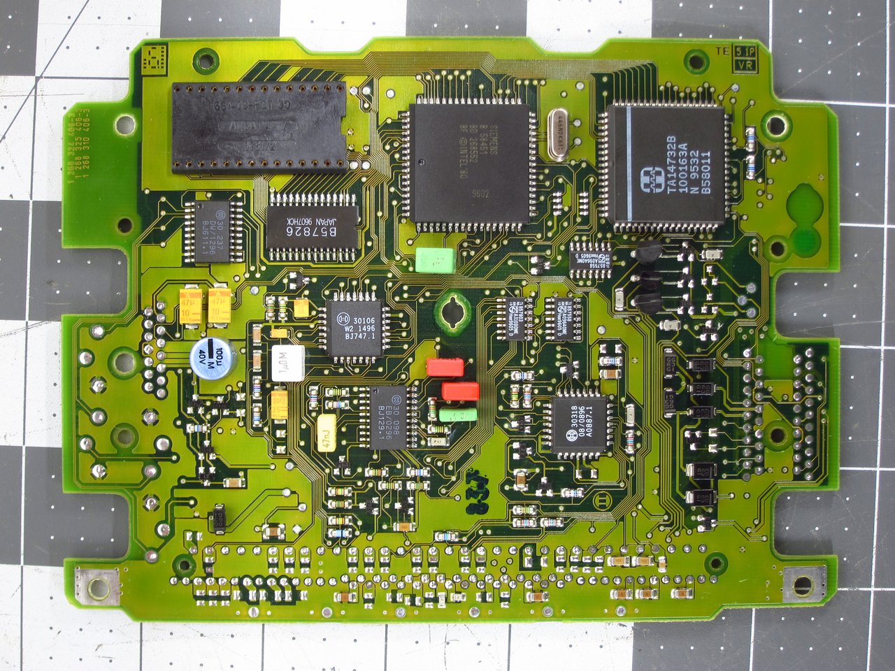
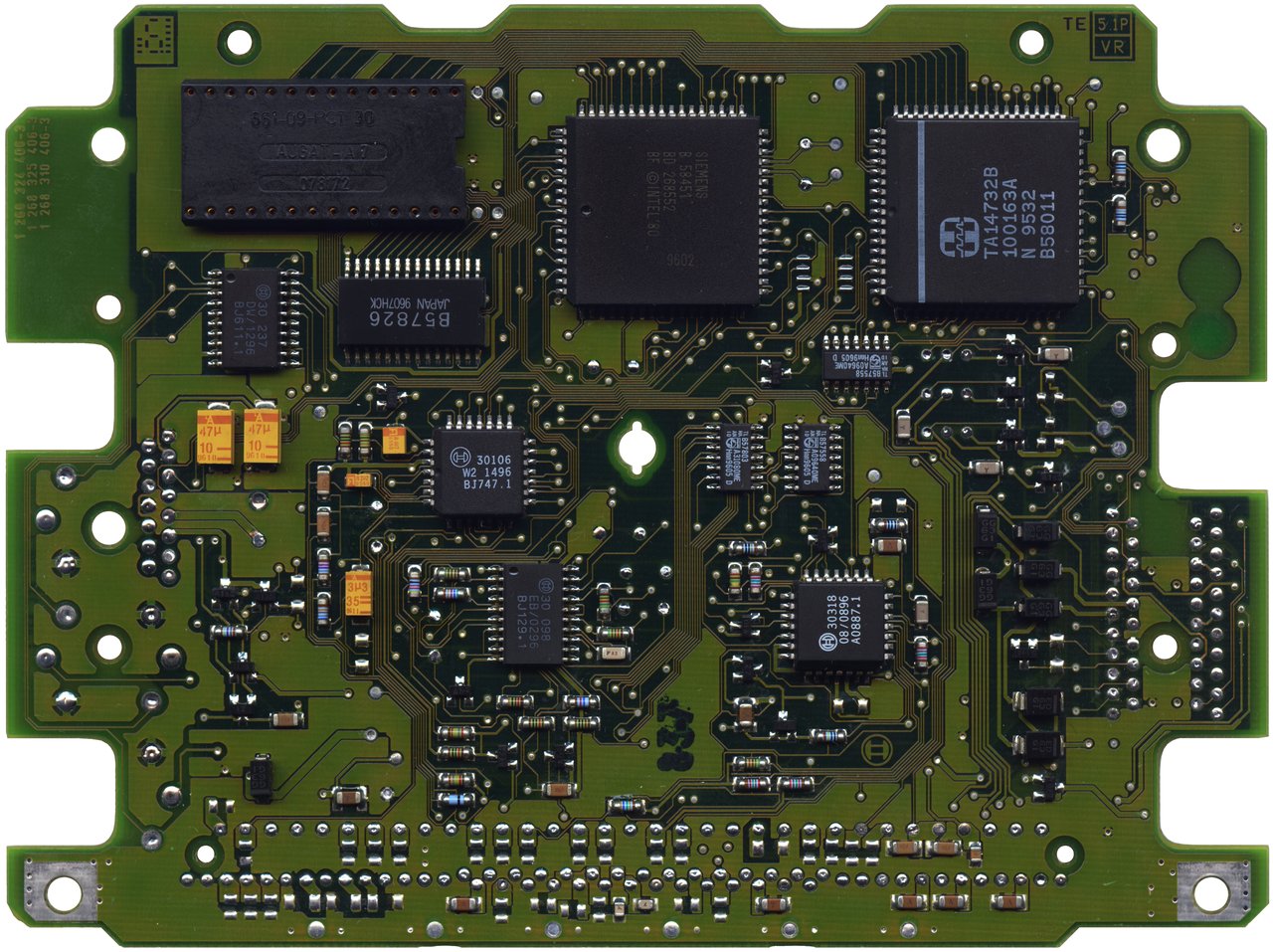
    2) Knock sensors. The E30 M42 block has the mounting bosses for them, so I just need to get the sensors. Which sensors is an open question though. My engine has 87mm bores, and knock sensing frequency is mainly proportional to piston diameter it seems. The sensors themselves may have a wide enough bandwidth, or maybe not, so I will have to get some used ones from an E36 M42 and test their frequency response. Also, I am certain that I will need to make analog modifications to the knock sensing circuit in the ECU since it is probably a very narrow band-pass filter tuned to the stock piston diameter. I will find this out soon enough when I fully reverse engineer the M1.7.3 ECU hardware though.

    3) Fuel injection. The stock E30 M42 wiring harness only has 2 wires going to the ECU for the injectors, firing them in pairs. M1.7.3 has 4 individual outputs, which are fired in pairs. My thought for now is to keep the factory 2-wire setup and install internal jumpers so that the driving transistors are still "sharing" the load.

    4) Coolant temp (CLT) sensor. Should be able to keep the stock one and simply modify the linearization maps.

    5) IAT. Should be the same deal as the CLT sensor.

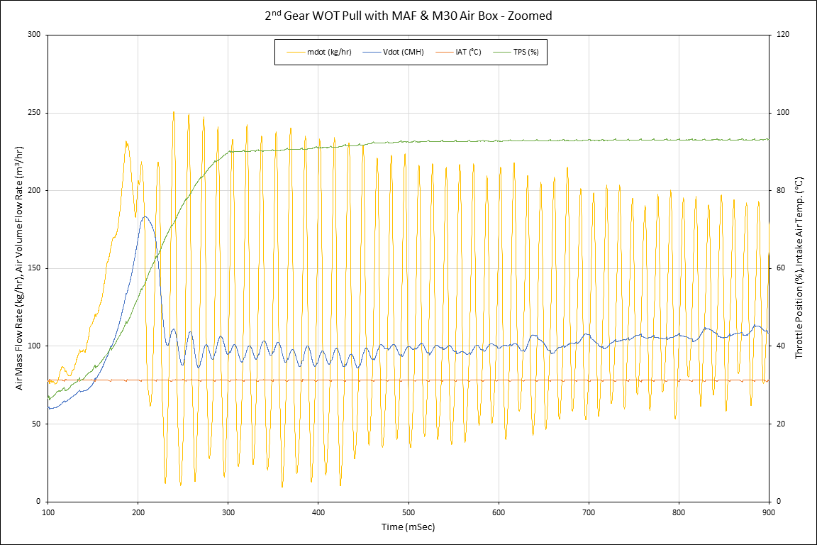
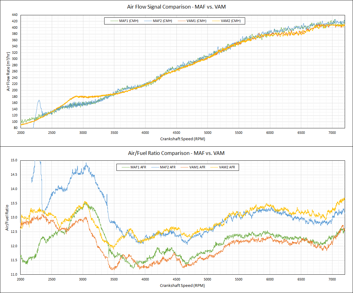
    6) MAF. Right now I have a stand-alone converter box which exactly mimics the stock VAM functionality using a VW MAF sensor. I can either stick with this and adjust the VAM transfer function in the software, or if the software can be modified to handle the MAF signal (very fast, large voltage swings at open throttle) I would love to do that.

    7) Wide-Band O2 sensing. For now this is just a "wish to have." I can keep using the narrow-band simulated output for a while until everything else works. Also, at least in M1.7, it seems that the O2 heater relay is turned off at full throttle, which was a problem for my wide-band system, so I jumped the relay to be always-on whenever the fuel pump relay was is active. With M1.7.3 I would prefer to have a working O2 relay so I suppose I can make sure that it is never disabled when the engine is running.

    8) EGS / ASC / EWS / DISA systems to be disabled in software since they do not apply here.

    9) M1.7.3 Pin 56...is this a separate 12V input for powering the ignition subsystems? It is labeled as "Ignition, Terminal 15" / "Ignition Lock" in the wiring diagrams.

    10) Dual temperature switch. I will need to check to see if the E30 coolant witch functions the same way. Also I do not even have AC installed and the aux electric fan is not present, so maybe I will see about disabling anything related to this in software.


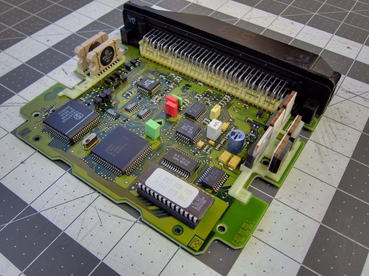
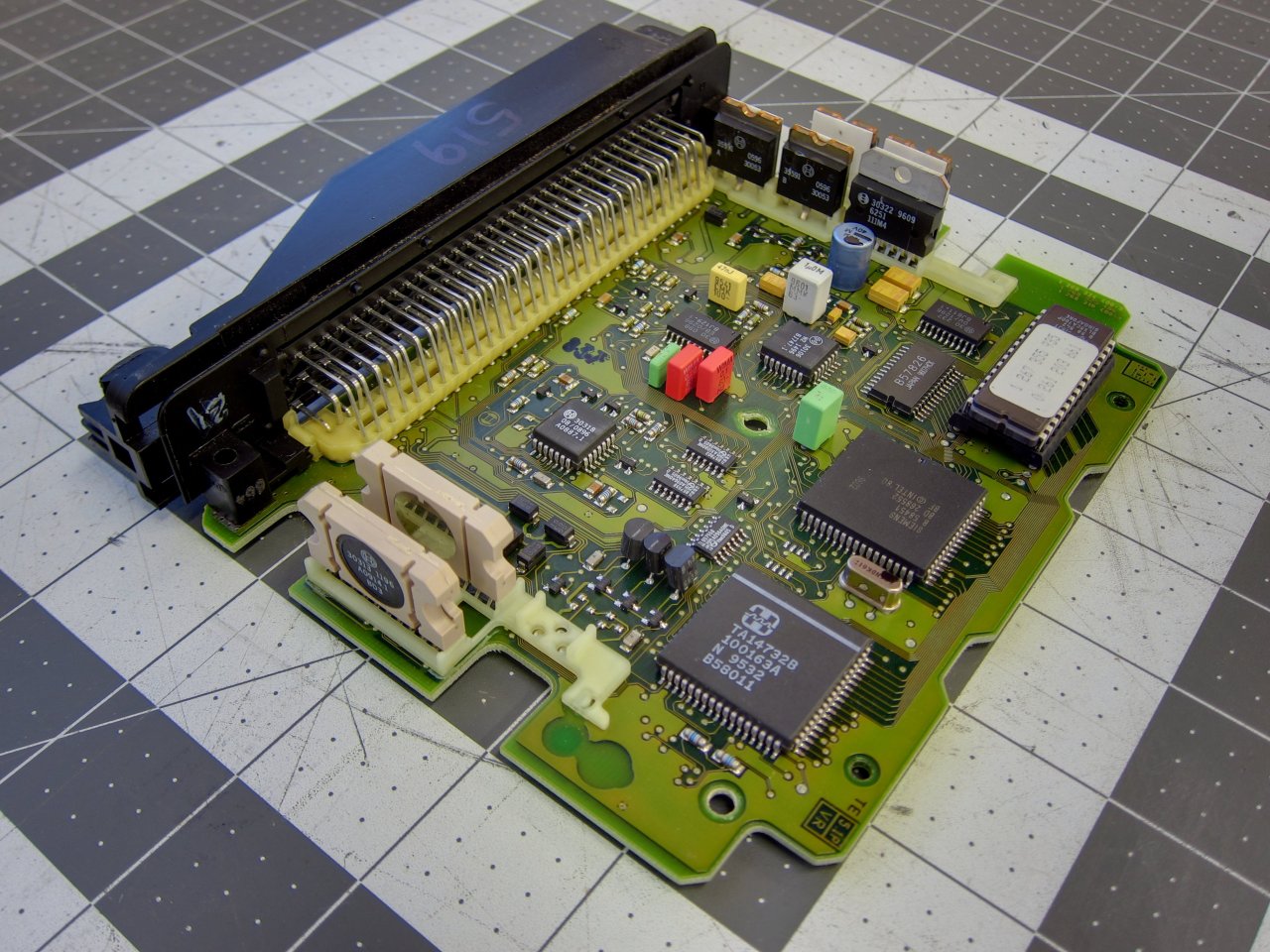
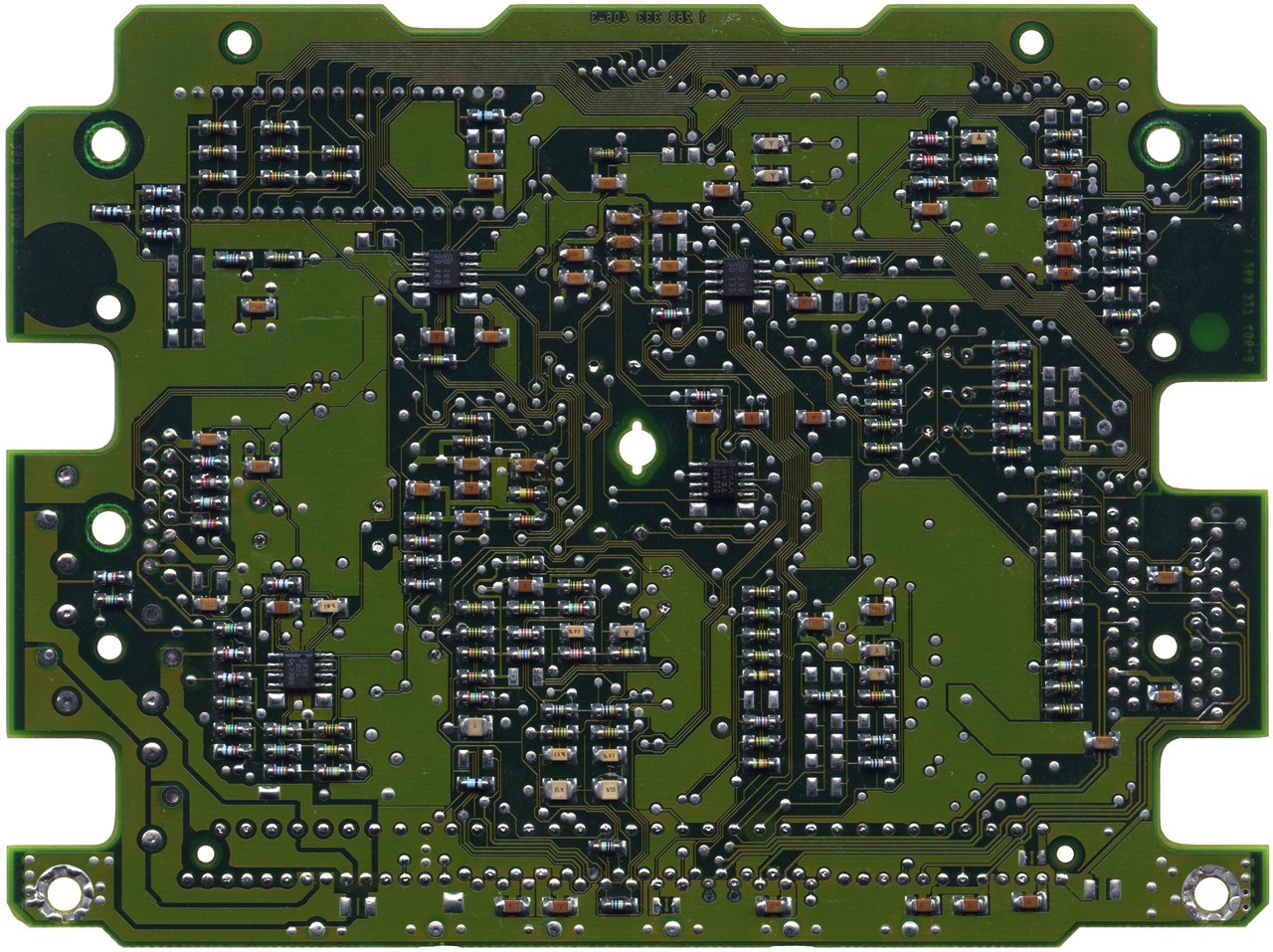
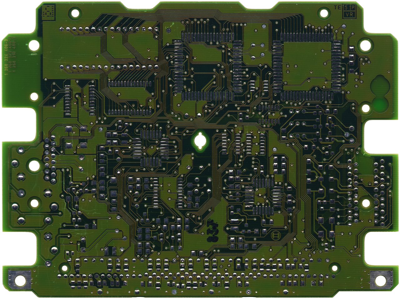
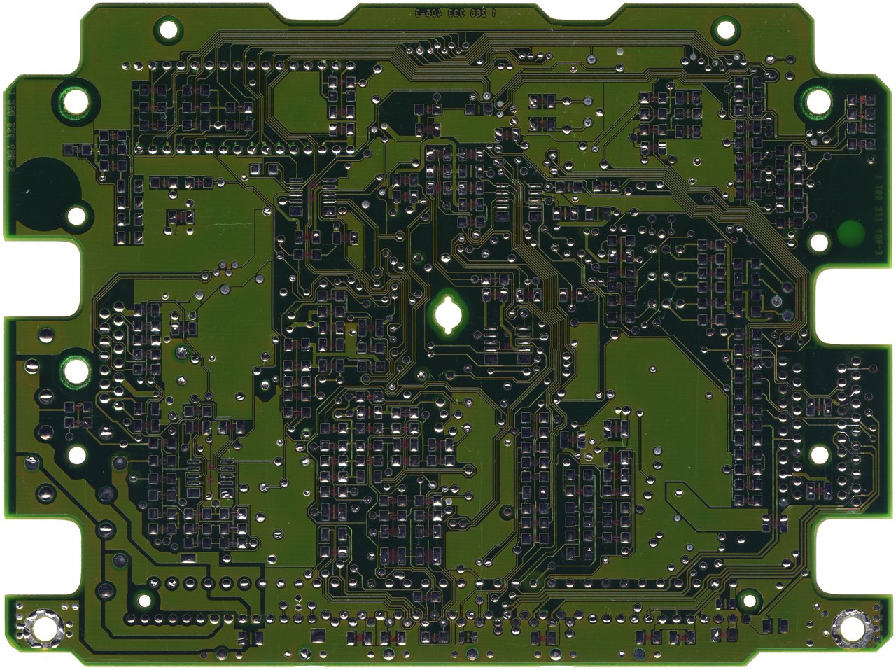
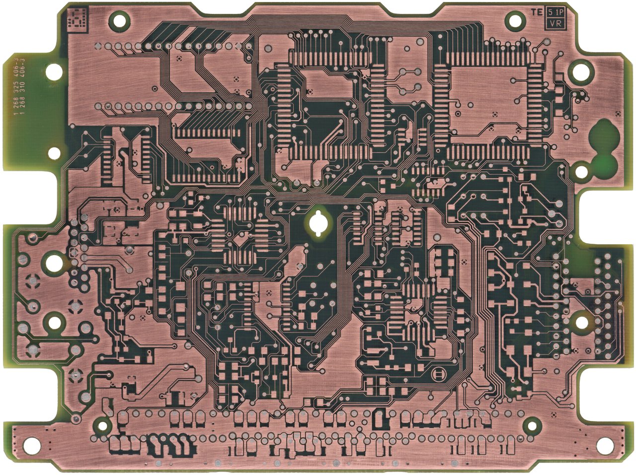
    OK, quite a list there. Priority #1 is going to be full reverse engineering of the M1.7.3 unit since that is needed to better understand things. The software is even more important to this of course, but I have less experience there, and there are some other helpful people here who know all about it. This will not be a quick overnight project!

    Link:
    E36 M43 wiring diagrams: http://www.e30tuner.com/assist/m173r...ngDiagrams.pdf
    Last edited by bmwman91; 02-09-2018, 12:29 PM.

    Transaction Feedback: LINK

    #2
    1) Need to buy M44 throttle body and just screw it, maximum - need to make some alu distance adapter from manifold to throttle body, if IAC valve will touch intake manifold.

    2) Completely mistake :) Bosch knock sensors are just like microphone, so difference is only in plug (so your choice depends on the used harness), sensitivity setting is done by software and few resistors I think. http://www.bosch-motorsport.de/conte...6740666635.pdf

    3) Best way is just put 4 new wire and M52B28 injectors with proper FGAT0 calibration (because stock M44 injectors has larger seating hole, and M43 has lower productivity).

    6) You can use your solution as in M1.7, M1.7.3 and M1.7 has same VAF, so dont need change any charastrerics except FGAT0 if you use non-stock injectors.

    7) Its work as in M1.7, so you need put your relay or modify software.

    8) EWS can be disabled, DISA DTC can be removed, not connected EGS / ASC will not produce any DTC.

    9) Pin 56 in M1.7.3 done same thing as in M1.7 its just ignithion switch - where do you insert the ignition key :)

    10) With this, you do not need to do anything I'm leave this system untoched and all works fine without DTC. Its bypass system for common cooleant fan switch.

    Comment


      #3
      1) I will see if I can find a local M44 owner to do some measurements with. My intake manifold has some custom welded resonance chambers on the "C" runners which make fitting anything else neat the TB very hard to do, but maybe the M44 one would bit. The outlet side of the M44 TB is also shaped differently than the E30 manifold port, so there would be a big "step" in the transition which I would not want, either. Take a look at page 14 of this PDF. I have the "Rally 2100" M42 engine in the car.


      2) Cool, so the sensors are fine, I just need to wire them and determine any changes in the ECU. Should be doable.

      3) It is a little harder than it may seem to convert to individual wire-per-injector. There is an intermediate 3-pin connector for the injector wire harness which is actually a separate part from the main harness. Converting to 4-wire would require me to either modify the existing setup to a 5-wire system (12V & 4 control lines), or to adapt an M44 harness. If I am going to continue running a 2 + 2 batched injection system, I am not sure if it is worth converting to a 4-wire setup. Also, the injectors in there now are standard EV1 bodies with the later style 4-hole atomizer and 24#/hr (255cc/min) flow rates, so I suppose that I just need to modify FGAT0 to match these? These are the ones I have in the car:


      6) Sounds good. Based on my testing, the main improvement with the MAF is the elimination of mechanical effects: the original VAM has a resonance at ~3000RPM and full throttle where it has a much higher output voltage than it should, and the original fuel maps are tuned for this by going quite lean in this area. Also, the stock VAM has bad over- and under-shoot as rapid throttle changes are made...I am not sure if the stock software is tuned to handle this. My MAF system has none of these problems, and I was able to make the WOT fuel maps more "linear" by removing the compensation for the original sensor resonance.

      However, I also had to design a very heavy low-pass filter to damp the MAF output because the ECU does not sample the VAM voltage fast enough to deal with this (or it does sample fast enough but the software is not written to process a MAF's fast response properly), and while the transient response is still faster than the VAM, it is a lot slower than just running the MAF directly (~20ms group delay for MAF+converter, versus ~40ms for the stock VAM and ~3ms for the MAF). It would be fantastic to be able to use the MAF directly, but that would require significant software changes since instantaneous MAF output will show every individual cylinder's air intake, versus the VAM which just damped all of it into a clean "average". MAF sampling would have to occur at specific crankshaft angles and have some simple averaging done (I was in the discussions on the MS3 forum about this years ago and they handled the MAF sensitivity this way).

      Here is some info I posted as I learned things over a couple of years. Lots of wrong info, but I later understood it better as I played with things:


      From that thread, here's the main example of why using a MAF directly is a problem. (yellow is raw MAF output, blue is converter/simulated-VAM output)


      7) OK, so no problem then.

      8) Nice

      9) So this would be called the "Start Input"?

      10) Cool.
      Last edited by bmwman91; 02-06-2018, 11:25 AM.

      Transaction Feedback: LINK

      Comment


        #4
        Originally posted by bmwman91 View Post
        Sounds good. Based on my testing, the main improvement with the MAF is the elimination of mechanical effects: the original VAM has a resonance at ~3000RPM and full throttle where it has a much higher output voltage than it should, and the original fuel maps are tuned for this by going quite lean in this area.
        Honestly do not quite understand what you're talking about, I did not see any lean in the WOT or Part-Throttle maps in M1.7.2 and M1.7.3, and it makes no sense, because VAF flap is very stable (of course I mean serviceable device) in all range and all jumps are smooth by special coefficient from RPM-based table (simple moving average).

        Stock VAF algorithm looks like:
        1) Get VAF value in the end of intake segment (180 Degree in 4 cylinder engine, 120 Degree in 6 cylinder engine) this is a maximum air volume point in cylinder
        2) Lineralize value to theoretical injection time and divide this value by RPM
        3) On this step we have cylinder filling represented in BTi and then it smoothed by simple moving average from previous intake cycle
        4) Convertation Volume to Mass (actually not, just percent shifting with value from IAT sensor based table, so VAF lineralization table is represent BTi in ms on temperature 20 Degree Celsius)

        Ideal MAF algorithm looks like:
        1) Get MAF value every 1 ms. from start to end of intake segment.
        2) Get average from values.
        All other steps same as in VAF processing, except 4 step.

        But in M1 there is no 1 ms. cycle, only 10 ms. its not enough, so best practice is combine technics from M1 and M2 with MAF.
        Need get value from two points in intake segment - 90 Degree (max pressure in cylinder) and 180 Degree (max volume in cylinder) for 4 cylinder engine and 60/120 for 6 cylinder, average value and smooth by simple moving average given from table based on TPS and RPM (separately from cylinder filling smothing from table based on RPM, for simplify setting).

        Your hardware solution is good and worked but it wrong, because you collect "weather on Mars" not cylinder filling values, because you not bind on crankshaft position.

        Comment


          #5
          Originally posted by Rasp View Post
          2) Completely mistake :) Bosch knock sensors are just like microphone, so difference is only in plug (so your choice depends on the used harness), sensitivity setting is done by software and few resistors I think. http://www.bosch-motorsport.de/conte...6740666635.pdf
          Is there any way to use this knock sensor with megasquirt on my 175 ecu m42? or with a megasquirt unit?
          318iS Track Rat :nice: www.drive4corners.com
          '86 325iX 3.1 Stroker Turbo '86 S38B36 325

          No one makes this car anymore. The government won't allow them, normal people won't buy them. So it's up to us: the freaks, the weirdos, the informed. To buy them, to appreciate them, and most importantly, to drive them.

          Comment


            #6
            Maybe the E30 M42 has certain unique characteristics due to its fixed-geometry intake manifold and stuff. Here is what I mean.
            Here are plots of the stock M1.7 WOT fuel map values [(14.7 * 128) / MAPVAL]


            And here is a live reading of the VAM output at WOT. You will see that there is a big increase in sensor output in the 2400-3400 RPM range, which is not actually reflecting real air flow, but rather an acoustic/mechanical resonance effect of the flap door in the sensor. It is most prominent at WOT when the intake pulses are minimally damped by the throttle plate, but you can also see similar leaning one in the high-load rows + 2400-3400RPM columns of the High-Part-Throttle fuel maps as well.

            Blue and green are air flow measurement from the MAF converter, yellow and orange are from the VAM sensor. All on the same engine (I was swapping sensors and making measurements).


            With respect to how my converter design was made and all that, you are correct that it was sort of a "weather on Mars" thing since I knew zero about anything in the ECU at the time. It was all engineering assumptions about what the ECU was expecting based on what the output signal of the VAM looked like. My assumption was that the ECU needed to know the mass of air drawn into each cylinder during each intake event in order to calculate the amount of fuel to inject. The VAM is way too slow to report true instantaneous air flow, and its output represents the instantaneous AVERAGE air flow rate into the engine (basically, it is a mechanical low-pass filter with a bandwidth of about 5Hz). Given that, and the fact that running the converter without a low-pass filter caused the ECU to cut fuel injection entirely at WOT over certain RPMs, I assumed that the ECU was sampling the VAM voltage at 100Hz or less.

            So I developed a converter which linearized the MAF signal into mass flow values, applied a digital low-pass filter with a ~20Hz bandwidth to the mass flow values, used IAT to convert the mass flow values to volume flow values (using PV=nRT), and then non-linearized the volume flow value into the corresponding VAM voltage in a DAC. This way, the ECU would receive a signal which would exactly match the one it would get from a VAM under all conditions (except, it turns out that the VAM had an RPM-dependent resonance). The other goal of the converter was to make it a product which would be 100% plug and play, no chipping or wire cutting needed. Obviously that was not going to be possible...either a chip with customized fuel tables was needed, or an ability to read RPM and TPS and mimic the resonance with the converter.

            Sorry for the long story. Hopefully it makes more sense now. If I am somehow completely wrong with my understanding, I would be interested to know too!

            Transaction Feedback: LINK

            Comment


              #7
              The other item, which is more fun than listening to me explain my weird black-box MAF conversion solution, is that my M1.7.3 ECUs arrived today. I went home at lunch time and popped one open to get some photos and start looking around. Yes, this is totally different than M1.7 and M1.7.2! The PCB layout technology, copper spacing pitches and solder mask color make this look a LOT more like M5.2 than any of the other M1.x units I have seen (meaning, it must have been designed in a similar time frame as M5.2). The core architecture may still be the 80C515/535, but I can tell that M1.7.3 is a lot more advanced in terms of PCB design techniques. Things are much more highly integrated, there are only 11 small through hole components (thank God), large copper ground pours exist and the component arrangement is much more cleanly organized. I will need to take much more care in reverse engineering this one since the copper signal traces are much thinner and will be easy to destroy when removing the solder mask layer. I like new challenges though!

              Images in the "all versions" collection are updated with the M1.7.3 pics.


              Just the M1.7.3 ones are below.

              Top view 1:


              Top view 2:


              Bottom view:


              Time to start making my plans to take it apart and build the schematic.
              Last edited by bmwman91; 02-07-2018, 04:56 PM.

              Transaction Feedback: LINK

              Comment


                #8
                Originally posted by downforce22 View Post
                Is there any way to use this knock sensor with megasquirt on my 175 ecu m42? or with a megasquirt unit?
                Sorry, I dont know, try to ask in megasquirt thread or forum.

                Originally posted by bmwman91 View Post
                Maybe the E30 M42 has certain unique characteristics due to its fixed-geometry intake manifold and stuff. Here is what I mean.
                Here are plots of the stock M1.7 WOT fuel map values [(14.7 * 128) / MAPVAL]
                Yes you right (again :) ), smooth load table in M1.7.X has only RPM axis, so hard to fix this issue only with it.

                Thats how it looks on M1.7.3 with proper scale.


                Can you post how looks like fixed tables?

                Comment


                  #9
                  Originally posted by bmwman91 View Post
                  The PCB layout technology, copper spacing pitches and solder mask color make this look a LOT more like M5.2 than any of the other M1.x units I have seen (meaning, it must have been designed in a similar time frame as M5.2).
                  Its designed on middle 90's, I think. For me its сuriosity that Bosch design new PCB, but leave old CPU (at that time already there is Bosch ECU with C517) without MDU and timers for making sequential injection without any problem and additional hardware and use mechanical load sensor...

                  All M1.7.3 improvements can be done only with software on old M1.7.2 DME, just properly connected two data pins from EPROM and short to ground another pin on CPU for use 64K. But maybe new PCB was more cheapest in production than M1.7.2, who knows... But at the same time was produced M1.7.2 for M42 engines and M1.7.3 discontinued with M1.7.2 on 96 year to go to BMS43 and M5.2.

                  And all discussed ECU fulfill only EURO-2 norms, so its not any sense release something further than M1.7.2, I dont understand where and why Bosch and BMW spend money and time, when it was only necessary to put MAF on old system, considering that he was already in M1.7 with V12.

                  Comment


                    #10
                    OK, good to know that I am not completely crazy in my understanding of the things I observed with the MAF converter project. The DISA manifold and maybe some other aspects of the E36 M4x engines are probably why the resonance behavior is so different.

                    I got all of the large through-hole parts off of the PCB tonight, only making 2 small damage areas which are easy to deal with in the image editor. The other thing which might be a problem is that there appear to be "blind" via holes (vias which do not go all the way through the board, but only between adjacent layers). If these are present, then reverse engineering will be an even bigger pain in the ass since I will have to start managing holes by layer rather than as simple through-holes. We shall see...

                    You can see the torn trace and the annular ring around one hole which was mashed up a little. No big deal since this ECU will never operate again.


                    Here is the current state of assembly. Once I get good high-resolution photos of the board like this to document components, I will depopulate everything and try to get the solder mask off. The not-used component spaces are going to be a little harder to deal with since I will not know which ones were jumpers, resistors or capacitors, but since they are not used it does not matter that much. I guess that the schematic I make for this will not be as complete as the one for M1.7 since there are no component references. Anyone got friends at Bosch who owe them favors, like a M1.7.3 layout+schematic? I did compare it to the M1.7.2 units, and I think that a lot of it is still the same or very similar, so I may be able to determine many component references by comparison. A lot of the different looking stuff on the main board is just the knock sensing components which got moved onto there.


                    Also, no need for a toaster oven so far lol. I think I can get the PLCC's and stuff off without one by using a small rotary cutter to cut the legs off of the plastic body, remove the body and then easily desolder the remaining legs individually.
                    Last edited by bmwman91; 02-08-2018, 01:41 AM.

                    Transaction Feedback: LINK

                    Comment


                      #11
                      Originally posted by bmwman91 View Post
                      Anyone got friends at Bosch who owe them favors, like a M1.7.3 layout+schematic?
                      If it was possible, we have been already have schematic :)

                      Originally posted by bmwman91 View Post
                      I did compare it to the M1.7.2 units, and I think that a lot of it is still the same or very similar, so I may be able to determine many component references by comparison.
                      I think most of components are same, software are competely same, except few ports.

                      Maybe full schematic no sense (we are not going to produce clones :) ), for reverse software need only principial schematic.

                      Comment


                        #12
                        I have made a Dropbox folder which will hold project files. Right now it is just the full high-resolution images of the boards (since I only post the shrunken ones in here) and a PDF of the E36 wiring diagrams. Rasp, I can make a sub-directory and give you editing permissions if you want a place to store things related to the software. No pressure, your choice.
                        General Info: https://www.dropbox.com/sh/70yvbe8f8..._Zt4JMGNa?dl=0

                        You are right, it may be not necessary to make a complete schematic since the goal is not to reproduce these. Mainly I want to understand the analog part of the knock sensing since it is possible that the filter will need adjustment for my larger piston diameters. We'll see as I dig into this more. I took the knock board off of one of my M1.7.2 units and got pictures of it. All of the parts look like they just moved to the main board on M1.7.3. As a convention, all of the "bottom side" images from boards are going to be flipped horizontally so as to align with the "top side" images.


                        Back to the M1.7.3 main board.....with all of the tall through-hole parts removed, I can actually use my flatbed scanner to image the PCB. It has ~5mm depth of focus (CCD type scanner). This saves me from many headaches which come from trying to make a panorama out of lots of photographs. Scans were done at 2400DPI, sharpened, shrunk to 50% size (1200DPI) and then color-corrected to look more clear and pleasant (which is important, because I am going to spend a LOT of time looking at them when I prepare to convert them to CAD!).


                        More to come! This weekend I will remove all of the components and work on getting to the copper, and possibly the inner layers if I have time. Still looking forward to a better understanding of the software, which I need to put more effort into understanding. Being a hardware guy, I always seem to choose to do the hardware projects first lol.
                        Last edited by bmwman91; 02-10-2018, 12:42 AM.

                        Transaction Feedback: LINK

                        Comment


                          #13
                          Good job! Yes, if you can - give me access to Dropbox sub-folder.

                          Comment


                            #14
                            Alrighty, the board is completely depopulated and cleaned now. The stupid 28-PLCC's had a bunch of pads tear off when I was cleaning solder off...it seems like my flux is attacking the bond between the copper and FR4 substrate or something. Maybe this board was made with different processes (the solder is lead-free as far as I can tell, because it is a big pain in the ass to solder...give me the good old-fashioned tin-lead stuff like the M1.7!). Anyway, it was easy enough to fix these in the image editor. Tomorrow or Sunday I will try my luck with removing the solder mask (without removing the copper with it!). I need to replace my water pump first though because it is getting noisy!

                            High resolution versions of these are in the Dropbox link.


                            I saved the various ICs that I removed just in case I decide to break the dies out and image them. There's not much functional value in doing that, but it is a lot of fun to get a really deep look into "everyday" things.
                            Last edited by bmwman91; 02-10-2018, 12:41 AM.

                            Transaction Feedback: LINK

                            Comment


                              #15
                              Today's update.

                              I got the soldermask off of both sides with minimal damage. This time I used a different approach. Previously, I was using a 3M metal polishing pad (a more abrasive "dish scrubber") and it seemed like that would be a problem here since it has a tendency to want to dig deeper in softer spots. This time I used a hard sanding block and some 400-grit sandpaper. This ensured that I was mostly keeping the abrasive action at the highest surface at all times. Naturally, the abrasion was more concentrated at board edges, and I did destroy traces near (what I assume is) S400 or S450, but since I have images from previous steps it was pretty easy to reconstruct everything. After the block, I went in by hand and touched-up some of the low spots on the board where soldermask was still present, and then went 800, 1500, 2000 grit. Polishing compounds are not recommended since a truly shiny surface shows up as being very dark, almost black, in the scanner. The 2000 grit paper left about as good of a finish as I needed to scan the board.

                              I am still doing some touch-up on the full resolution images, so I will post those in the Dropbox in a day or two when I am done checking them over to make sure that I fixed all damaged copper. For now, here is how the top side is looking.


                              Once the image clean-up is done, I will see about getting this thing on a mill so that I can get at the inner layers. It should go more smoothly this time since a) I have some idea of what I am doing and b) there are no bubbles in between layers.

                              Transaction Feedback: LINK

                              Comment

                              Working...
                              X