Announcement

Collapse
No announcement yet.

Yet another request for advice on a stroker

Collapse
X
 
  • Filter
  • Time
  • Show
Clear All
new posts

    #16
    so whats the argument about +1 valves. They are about the same price as stardard valves from IE. I was going to go +1 all the way around on my head, but i haven't gotten any feedback so to speak on whether its worthwhile or not. Mine will be a turbo though.

    off topic - nando the 3.64 gearing is all cleaned up new fasteners on the way. also i got a new diff mount which was super expensive. i hope to have that installed before the end of november.

    Comment


      #17
      I dunno, I avoided buying stuff from IE, except for my AFPR. I got all my valves from BMA, they were about half the price of the +1 valves. that adds up when you need to buy 12 of them, plus there is the valve shrouding problem to consider. I just didn't think it was worth it.
      Build thread

      Bimmerlabs

      Comment


        #18
        Originally posted by nando View Post
        I dunno, I avoided buying stuff from IE, except for my AFPR. I got all my valves from BMA, they were about half the price of the +1 valves. that adds up when you need to buy 12 of them, plus there is the valve shrouding problem to consider. I just didn't think it was worth it.
        sending the head down to MM seems like a better option all the time. by the time i buy all this stuff and have it machined its going to be up there in price anyway. not sure how well that head is suited for a log manifold though, i may have to call again.

        Comment


          #19
          I know. I spent about the same on my head as the MM one, and I didn't get the x-rayed rocker arms, CNC'd ports or any of the other fancy stuff. :(
          Build thread

          Bimmerlabs

          Comment


            #20
            Originally posted by nando View Post
            I know. I spent about the same on my head as the MM one, and I didn't get the x-rayed rocker arms, CNC'd ports or any of the other fancy stuff. :(

            maybe i'll sell my cam and springs and just send it down there. they do produce a sick head.

            Comment


              #21
              Hi Gavin

              Have you given any thought to the length & diameter of your runners up to the TBs and what length trumpets you are going to use ?

              Decisions you make regarding those factors will have quite an effect on air speed in the intake system. This in turn leads you to the next problem, viz. where do you locate your injectors.

              Fuel atomisation is very important. If you locate the injectors far out ,e.g. outside the inlet trumpets, then at high rpm the fuel travels for a long time in high speed (and turbulent air as is passes throttle plate) allowing more time for the fuel mix evenly. The longer travel also means that the fuel can draw more heat out of the ingoing air, this improves fuel vapourization and leads to a denser air charge. All these positive influences in addition to their own benefits also allow you to safely run a higher compression ratio.

              For low rpm with low air speed you need the injectors closer to the valve to work as effectively as possible.

              I am going to run a dual injector setup with my throttle bodies on the 3.1 liter M20 stroker. The standalone engine management will fade out the closer injectors and inject the majority of the fuel from the outboard injectors as rpm rises.

              Comment


                #22
                Andreas,

                I’m planning the same injector set up you’re talking about. 12 injectors, switching over to the second up-stream set at higher RPM; but that might be a future upgrade for me. I think I’ll start by just getting things running with 6 injectors in the stock locations.

                -My runners are 1.5” ID.

                -I should have about 8” of runner length between the head and each TB butterfly.

                -As for trumpets, I’ve got a slightly unusual plan in mind:
                As my runner ID is somewhat large for the RPM I’ll be running at, I’d like to keep my total runner length (from the head to the velocity stacks) fairly long. I plan to fabricate a tubular manifold to feed the 6 TB’s that will snake out my 6 runners (at equal length/resistance-to-flow of course) to 6 separate velocity stacks and filters (I still need to figure out exactly how I’ll position these) as to give me around 20” of total length. Wide but long runners should still net me good flow characteristics, as long as I can keep my bends nice and smooth.

                Let me know how your project progresses and I’ll be sure to do the same. Looks like were going to encounter a lot of the same issues.

                Comment


                  #23
                  Originally posted by Gavin View Post
                  Andreas,

                  I’m planning the same injector set up you’re talking about. 12 injectors, switching over to the second up-stream set at higher RPM; but that might be a future upgrade for me. I think I’ll start by just getting things running with 6 injectors in the stock locations.

                  -My runners are 1.5” ID.

                  -I should have about 8” of runner length between the head and each TB butterfly.

                  -As for trumpets, I’ve got a slightly unusual plan in mind:
                  As my runner ID is somewhat large for the RPM I’ll be running at, I’d like to keep my total runner length (from the head to the velocity stacks) fairly long. I plan to fabricate a tubular manifold to feed the 6 TB’s that will snake out my 6 runners (at equal length/resistance-to-flow of course) to 6 separate velocity stacks and filters (I still need to figure out exactly how I’ll position these) as to give me around 20” of total length. Wide but long runners should still net me good flow characteristics, as long as I can keep my bends nice and smooth.

                  Let me know how your project progresses and I’ll be sure to do the same. Looks like were going to encounter a lot of the same issues.
                  38mm runners are just about perfect for a 42mm (less stem diameter) intake valve, I wouldn't be worried about designing extra length into the intake system. My TBs are 45mm which is in all probability too big.

                  We've designed an intake manifold on our CAD/CAM software to smoothly blend from the round bore of the TB to the rectangular shape of the intake port on the head. I could go and exchange my TBs for 40mm but this would make for a more difficult transition between the two shapes, especially when regarding it from a tooling / machining point of view.

                  That's why I am staying 45mm for now and seeing how it turns out, I can always change later. With my 304deg cam (maybe also hopelessly too big) I want to see if I can make power until about 7,500 rpm, so who knows, the 45mm might come in handy after all.

                  20" long intake runners, whow that's quite long. You're gonna have to twist and curve the pipes quite a bit to fit that in the engine bay ; and those bends would pretty much kill the idea of putting a 2cd set of injectors further away from the throttle plates.

                  Are you able to clear your brake booster with your intended setup ?

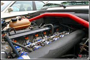
                  Here are some pics of my throttle bodies, I would like to see pics of yours as well ,if possible.


                  Here is a partially machined intake manifold. Note how we angled it so as to get the airflow as straight as possible onto the valve and thus eliminate any sharp bends for the airflow as encountered with the standard M20 intake manifold.


                  Here are some pictures of what BMW did with the E46 M3


                  Comment


                    #24
                    Are you able to clear your brake booster with your intended setup ?
                    I should have lots of room once I swap in my replacement booster/ master cylinder. I scavenged the brake guts from an older 735 (much smaller diameter unit than my stock fat boy), it should give me the clearance I need to snake a little tubing (or carbon if I decide to go that route).

                    I’ll be happy to post some photos of my set up once I start assembling. Right now all I have is a pile of parts (a chopped down intake manifold and a few sets of GSXR 1000 41mm throttle bodies).

                    Comment


                      #25
                      I’m starting to assemble my DIY ITB’s now and have a question to pose for those who are wise in the ways of fuel management.

                      As to remove the stock 0 – 5v AFM I had planned to create a vacuum manifold, to link the 6 separate intake runners, and substitute a 0 – 5v MAP sensor for the old AFM set up. Obviously the voltage outputs of these 2 sensors will not properly overlap, so I had planned to use an APEXi Neo (in conjunction with a wideband O2) to modify the MAP sensor voltage, based on RPM, and adjust for the new fueling requirements of my system. Since I first came up with this plan however I’ve read in several spots that MAP based tuning of ITB’s can be problematic; bouncing signal, lack of vacuum, insufficient vacuum gradient, ect.

                      This has me thinking about a crude ‘Alpha N’ set up of sorts where I would use 0 – 5v TPS signal, referenced against RPM & modified by the Neo again, in place of the MAP signal to tune fuel. I would need to come up with some sort of correction for atmospheric pressure variation, and this system would be admittedly crude, but it seems to make sense to me. I’d be adding fuel based on throttle position, corrected for engine load based on RPM. Not an optimal way to accomplish my goal, but perhaps a functional and relatively inexpensive one.

                      Can anyone offer me any advice on this sort of set up?

                      Comment


                        #26
                        I saw that someone mentioned they paid $250 for "head work and a valve job".

                        The power you make is going to be in the cylinder head, now I only have concrete numbers for V8 Modern Chrysler applications but a true race porting can probably carry over to other applications.

                        An out of the box Mopar R/T head flows about 220 cfm's on the intake side, with about $1000 worth of port work for both heads you can get that into the 305cfm range.

                        cliffs notes: find a good cylinder head porting shop and spend your bucks there, back cut the valves, focus on porting rather than polishing to a mirror, coat the pistons and use the most lift as possible that matches the cylinder heads flow aspects.

                        Comment


                          #27
                          Gavin, I thought about doing the MAP adjusting with an apexi also. I've got an SAFC on my stroker, but using alpha N style adjustments. But I still have a maf input, and it's no where near a restriction, according to the apexi it's only flowing 55% at WOT. So I'm actually thinking of adding it back in when I throw my 34mm throttle bodied ITB setup on.

                          But I have seen people use a vacuum manifold to converge all 6 vacuum sources into one source to feed a MAP sensor. Have you looked into megasquirt any? as You can run a hybrid Alpha N setup on it, where it uses Alpha N at lower load rpm spots and then MAP at higher rpm's and loads.
                          85 325e 2.7 ITB'd stroker

                          Comment


                            #28
                            Yes, I’ve actually thought a lot about using a Megasquirt set up. The Megasquirt could properly take care of all my fueling needs and if I purchased the correct unit/accessories I could upgrade to control ignition timing as well. But to be honest I’ve never wired in (and tuned) any electronic components that complicated before and I’m a little leery of it. I’ve done plenty of stereo (and some limited piggyback) wiring, but that’s a far cry from the complexity of installing a MS.

                            Comment


                              #29
                              The E46 M3 has individual throttle bodies and uses a MAP sensor. In the one and a half years that I drove this car, it never stumbled with the fuel injection.

                              The E46 M3 CSL also has ITBs but uses Alpha-N fuel management. In the two years that I've owned this car, I have twice done something with the throttle that confused the engine management and caused a momentary stutter.

                              The M3 CSL is set to permanently run 5% rich. I don't know why this is so but maybe that is the only way that BMW could overcome some problem.

                              Judging from this, I would say that maybe using a MAP sensor would be the easier option.

                              Comment


                                #30
                                does the e46 m3, have some sort of accumulation manifold for all the vacuum hoses coming from each cylinder? My friend has an e46m3 and his only complaint it the idle hunts all over the place. He's taken it in many times, but it won't throw a code so they won't touch it. I think it's just the throttles out a sync a little.
                                85 325e 2.7 ITB'd stroker

                                Comment

                                Working...
                                X