
Yeah the more I check around online the more I hear about injectors sticking if they sit outside of a fuel rail for too long. I have a programmable power supply (0-50V / 3A) that I can use to pulse them since it allows me to program on/off sequences. I assume I probably want to do something like 5ms ON / 1 sec OFF if I am running 20V through them so that I don't burn out the coils? Since these were cleaned and I know that there is no gunk or crap in them, it stands to reason that I do not need to run any cleaner through since whatever is sticking them shut is a very thin film of congealed oil.
Sssquid also mentioned that he has seen a small number of cases of cleaned injectors being stuck shut after sitting for months. If I do end up removing them, I will probably toss them into an ultrasonic bath with some isopropyl alcohol, and pulse them while immersed. Fingers are crossed that I can just un-stick them without taking things apart.
-
-
Yes, it was recent that someone here had stuck injectors after cleaning. It happens more than you would like to think.
Before yanking it apart, verify the injectors are getting signal. If they are, the sometimes reversing polarity, or/or hitting them with a little extra current will sometimes free them if it hasn't been too long. I have a -20v DC reg power supply and have hit them with 20v to get them to fire. If they click then they should be functional.Leave a comment:
-
I've also heard of the wrong pintle caps being used after an injector rebuild, which blocks the fuel from spraying. If you do pull the injectors, can you leave them attached to the harness and fuel rail so you can see the spray pattern and test them (into some clear bottles)?
Leave a comment:
-
I got an ignition tester light and verified that coil 1 was in fact firing. Based on the frequency of pulses and how they slowed after cranking for ~3 seconds, I know that the crank and cam signals are good since it indicates switching from wasted spark to COP mode. All coils are new, and I checked that all of the coil control lines route to the correct ECU pin.
I also got a fuel pressure test kit and stuck it inline with the outlet of the fuel filter. While cranking the system builds a rock-steady 46PSI, so the feed is good it seems. The lack of fuel being injected comes down to the injectors, either because they are stuck, or because they are not being fired by the ECU. The injector sub-harness seems to be good since I get 7.4 Ohms between the 12V supply and 2 control lines (injectors are fired in parallel pairs). I am going to yank the upper manifold so that I can look into the lower manifold while cranking to see if there is any sort of spray coming out of the injectors. If not, then they are coming off for bench testing and cleaning (despite being cleaned recently). I want to say I recall at least one person on here having all 4 injectors stuck after they were cleaned (and maybe sitting for a while)...anyone else remember that?Leave a comment:
-
Thanks. Yeah, wiring is a lot of work, doubly so when you are trying to do it correctly.
So I have it all back together and ready to go. With the spark plugs out and belts off, I ran the starter for ~25 seconds at which point the oil pressure light turned off. There was assembly lube packed all up in there, so I figure that 25 seconds of no-load cranking is not too bad.
Today I wrapped up the last of the wiring for the COP coils (a proper trim job with new terminals, and a LOT of thought behind how I strain-relieved the harness running to the engine). Unfortunately, the engine will not start. It cranks fine, but there is zero indication of combustion. It's late and I had lots of other stuff going on so there was not time to try much in the way of troubleshooting, although I probed around a bit to find stuff coming up normal.
I still need to verify that I am getting spark.
As far as fuel, I believe that this may be the issue. After cranking for 20 seconds in a closed garage (after trying in the driveway to no avail and pushing it back inside) I was only able to get the faintest whiff of fuel when I stuck my nose in the exhaust tip. I am not sure what is normal since I have never had a fuel issue, but I would expect it to stink of gas a lot more after that much cranking.
There are 2 things I am thinking it could be.
1) Fuel pressure regulator. It was working fine when the engine stopped running. However I blasted it out with brake cleaner before putting it back in, just to get any dust and gas residue out. Is there anything in there that would be damaged such that it would not allow pressure to build? I am not getting any fuel in the vacuum line or anything.
2) Fuel pump. Like an idiot, a couple of weeks ago I ran it "backwards" for a minute or two. Again, the goal was to mix up the fuel in the tank and dissolve any dried residue in the lines that sat empty for 6 months. I realized it was backwards because it blew the 7.5A in-line safety fuse I put between it and the battery (engine wire harness was out of the car entirely, nothing else was connected to the battery). The battery had 12V hooked to a chassis ground lug and the negative terminal hooked to terminal 13 of C101, which ONLY connects to the fuel pump as far as I know, so nothing else in the car could have been reversed. Anyway, after I realized the mistake I connected the polarity properly, put in a new 7.5A fuse and ran the pump forward for 5 minutes without issue (I took a hose scrap and connected the feed and return lines directly, no rail). Anyway, could running it backwards have caused it to be unable to build proper pressure? The fuel tank is full, so it is at least fully immersed.
3) This seems the least likely, but maybe stuck injectors? I had Sssquid clean and flow bench my injectors months ago, and they have sat for months in their little sealed baggies until just recently. Could whatever ran through them last have varnished up and plugged the injectors?
With the engine all assembled, if I jump the fuel pump I can hear it whirring, and I hear a lot of hissing coming from the fuel rail/regulator area. Honestly I have never run the fuel pump with the car off, so I have no idea if the rail supposed to make noise or not. The rubber feed line into the rail has a little vibration, and the return line from the rail has much more noticeable vibration in it.
I have quadruple checked the line connections and unless I am missing something, those are not swapped either. The silver connector pipe (going to rear-most barb on the rail) is the feed inlet based on the RealOEM diagram, and that connects to the chassis hard line that comes out of the fuel filter. The black connector pipe (from front-most barb on rail) should then be the return, and it goes to the rear-most of the 3 8mm chassis lines that sit by the charcoal can. I visually traced the line from the filter to the silver/rear inlet of the rail, so I am pretty sure that is corect.
Next steps are to get a fuel pressure gauge on there to see what I read, as well as verify that I am getting sparks by pulling a plug & coil and watching for the spark with the body of the plug grounded during cranking.
Does the tach read anything during cranking? I notice that while cranking the needle does not move. The Motronic sends a tach pulse every time an ignition coil fires, at least when running normally, so if it is supposed to indicate 400RPM or whatever it cranks at it isn't. I may get an oscilloscope on the crank sensor pin on the Motronic connector to verify that I have a good signal (the sensor and damper wheel are both basically new still, although the sensor might have gotten bonked in the last 6 months while it was in a box).
Anywho...clearly my brain is in super duper troubleshooting mode lol. Cam and crank timing are good as far as I can tell, so it isn't the case that MM reassembled it wrong. The thing cranks strong, build oil pressure and looks ready to go, other than the fact that it won't run!Leave a comment:
-
Nice work on the harness, I don't think people realize the time that takes. Let alone the wiring diagram above for the engine. Thank you, I will tuck that away in my files for reference. I have been working on doing chassis wiring and looking at a lot of wiring diagrams to retain original functionality, but that is only for the chassis wiring, your diagram will be a great reference for the engine harness and I like how it shows the fusible link wiring which is helpful when I was looking at how to wire my master power kill switch.
That is the only/ most accurate diagram I have seen for the m42 by the way.Last edited by downforce22; 06-04-2020, 09:31 AM.Leave a comment:
-
OK party people, I have my balanced flywheel and pressure plate back and am working on final assembly of the engine this weekend. The RHD flywheel was within ~1g of perfect, and the OEM Sachs M20 PP was maybe 10g off, so relatively little material needed to be removed. The final result was a pairing with a total dynamic unbalance of 0.9g, which is effectively negligible. Hell, it would have been perfectly good without the balancing, but since I have the time I figure it won't hurt.
For reference, I had Cardelli Motorsports in San Mateo CA do it. I chatted with the owner, Steve, and he has a ton of business right now. Apparently everyone who is sheltering in place at home is finally getting around to their engine rebuilds!
Anyway, I am taking pictures and will get to posting those and (needlessly long) descriptions later tonight or tomorrow.Leave a comment:
-
Ha! Man, memories of pirated games of my childhood, on a computer that could barely handle the graphics!
Here's the photo dump from today, as well as other stuff I wrapped up over the last week.
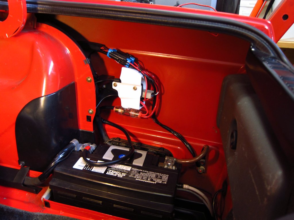
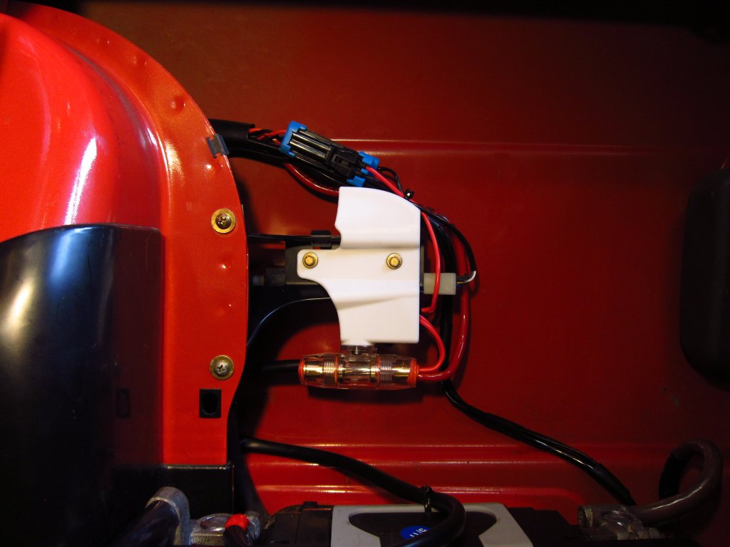
This is the final fuse holder / wire guide bracket as it now sits installed in the car. It is not exactly OEM-neatness, but it is a hell of a lot better than what it was like before, and there is nothing rattling around next to the battery or catching on it anymore. Getting the gas door lock plunger back into the rubber bellows was also easy, but only because I cleaned it (plunger and bellows) and applied a little silicone lube to the plunger. Otherwise it would have been impossible with the fuse holder in the way since it was all sticky and gross. Also, I was going to replace the rubber bellows and mating piece on the outside, but the bellows is like $70 lol. This one is just a little old and deformed, not torn, so I put a little RTV around the perimeter before reinstalling it which should (hopefully) be enough to seal it.
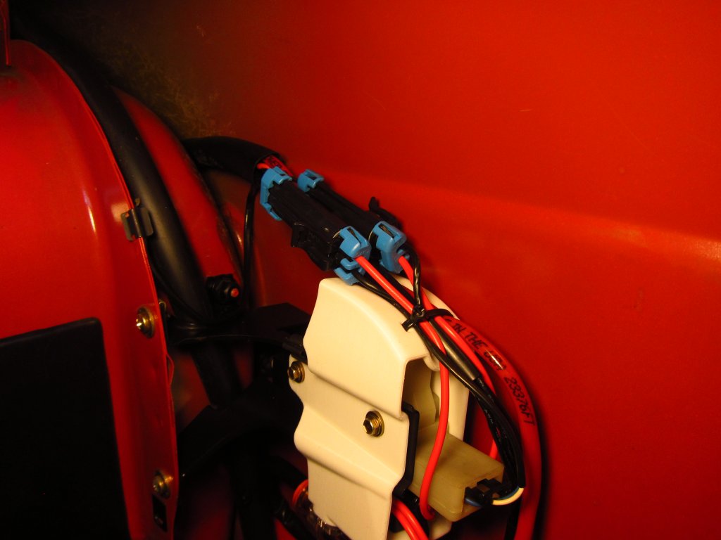
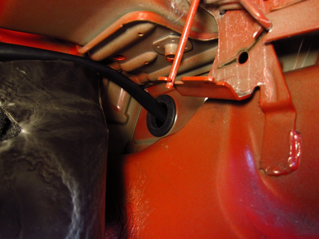
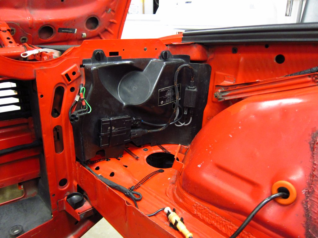
As mentioned before, I ran the power wiring through an opening in the bulkhead on the passenger side, and through the space above the rear wheelwell. There is no grommet there normally, and the opening is 50mm in diameter, so I just bought a grommet on McMaster (9600K328) and installed it to prevent anything from rubbing on a sheet metal edge.
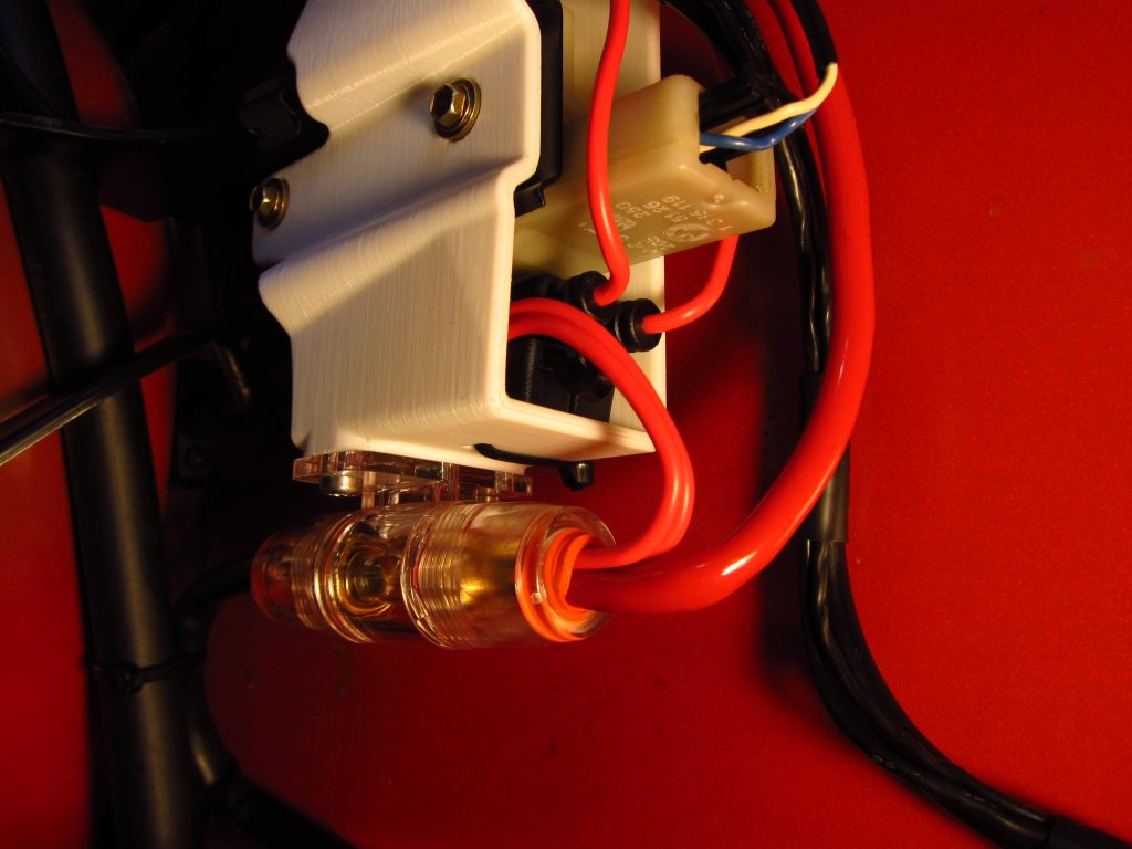
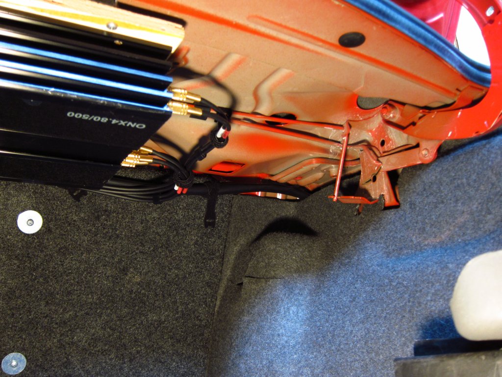
And there it is, all cleaned up and no longer running on the floor of the cargo area! It used to run parallel to the main positive cable from the battery, but it was still ugly.
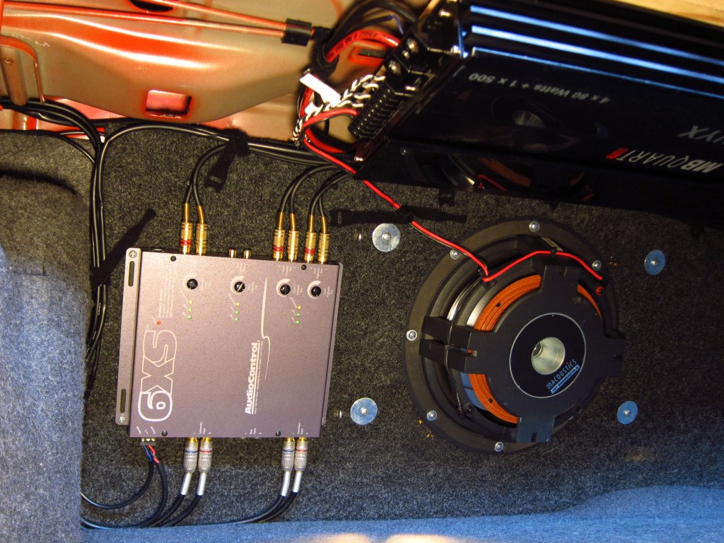
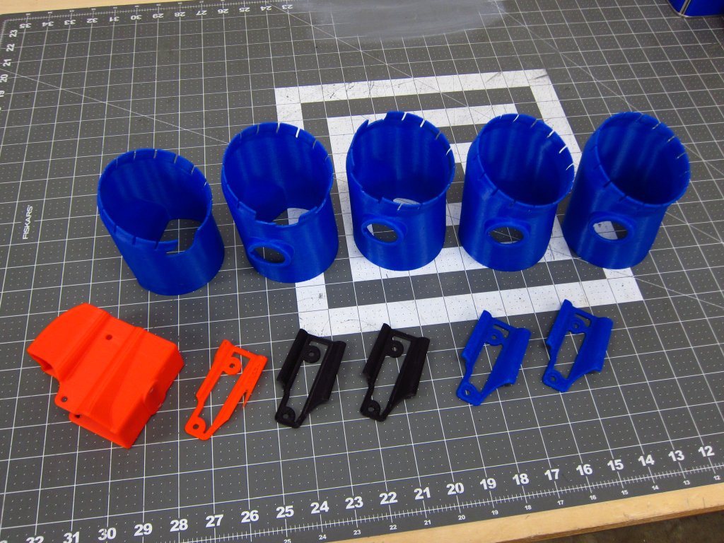
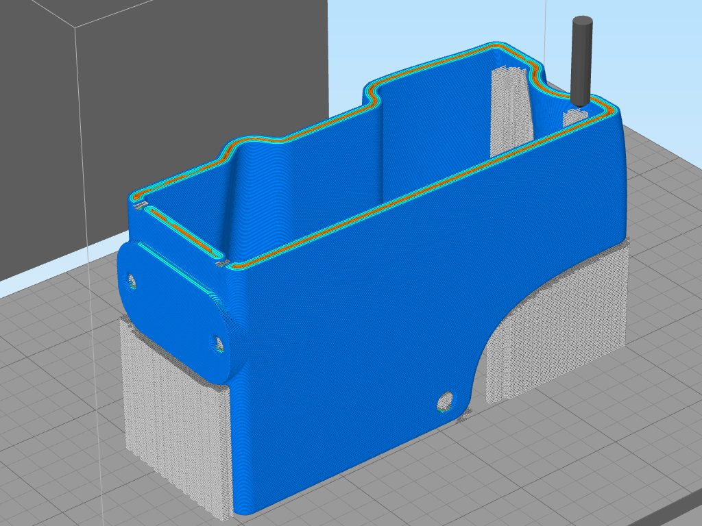
OK, so that is more or less it for the stuff that has exactly zero to do with the original topic of this thread! I'll probably cross-post some of this in my old audio system design + build threads. Anyway...Here is the pile of 3D printed proto parts that came from all of this. That 3D printer was definitely a worthwhile investment!
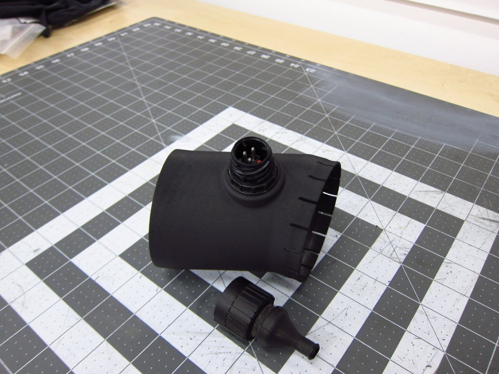
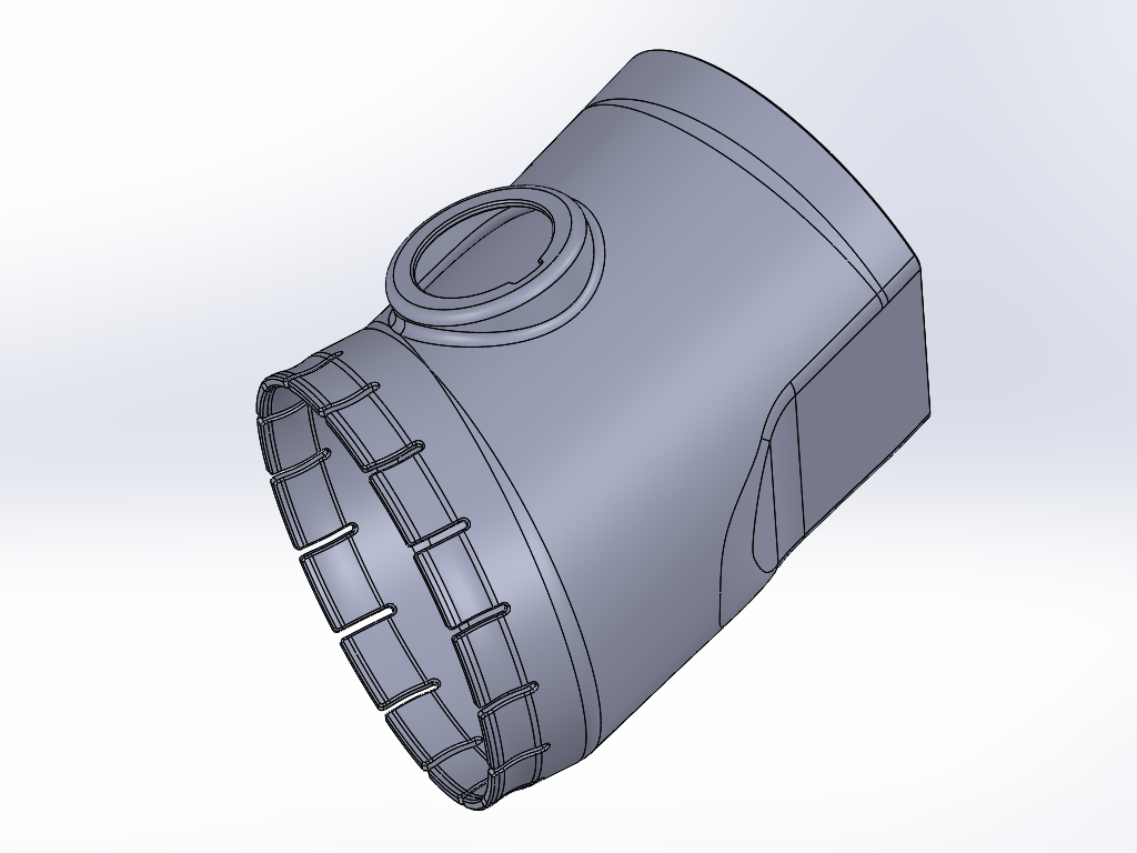
This is the final adapter for the M30 air box. It is SLS Nylon, with some flat black paint. It also has the connector housing which I used as a holder for the IAT thermistors.
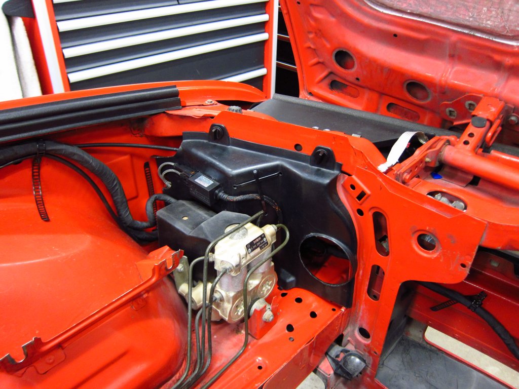
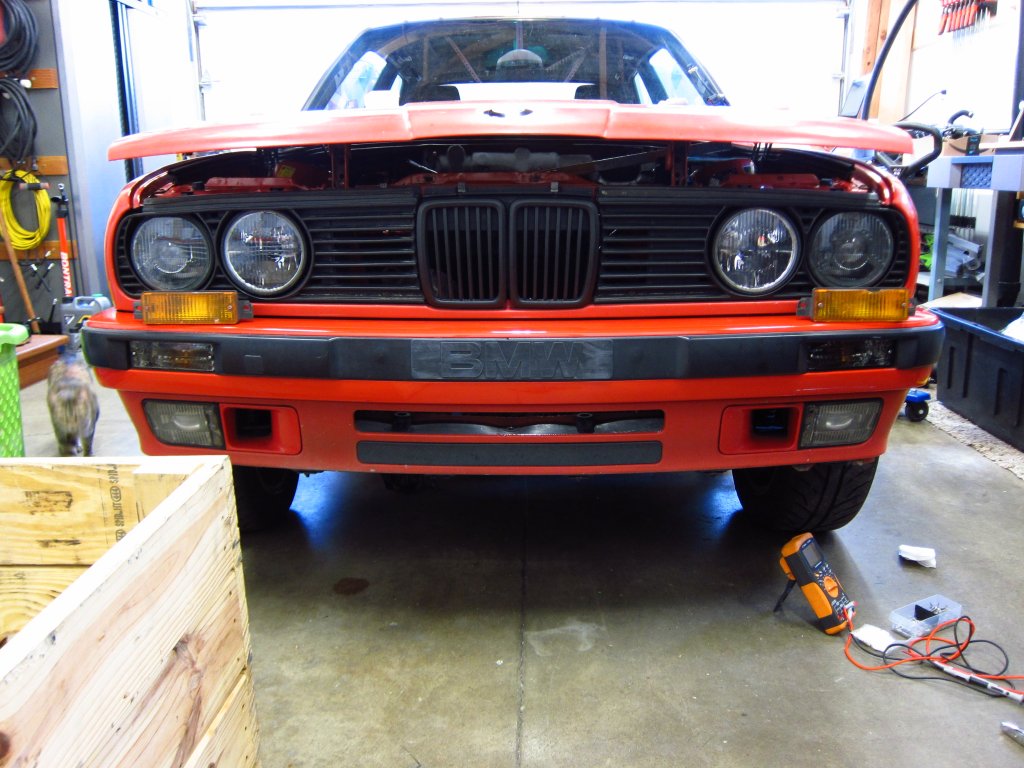
Here it is installed with the M30 air box . The MAF is a VW unit that I developed a converter for, and lots of the other wiring I did in previous posts was to make the converter box integrate more cleanly with the factory harness.
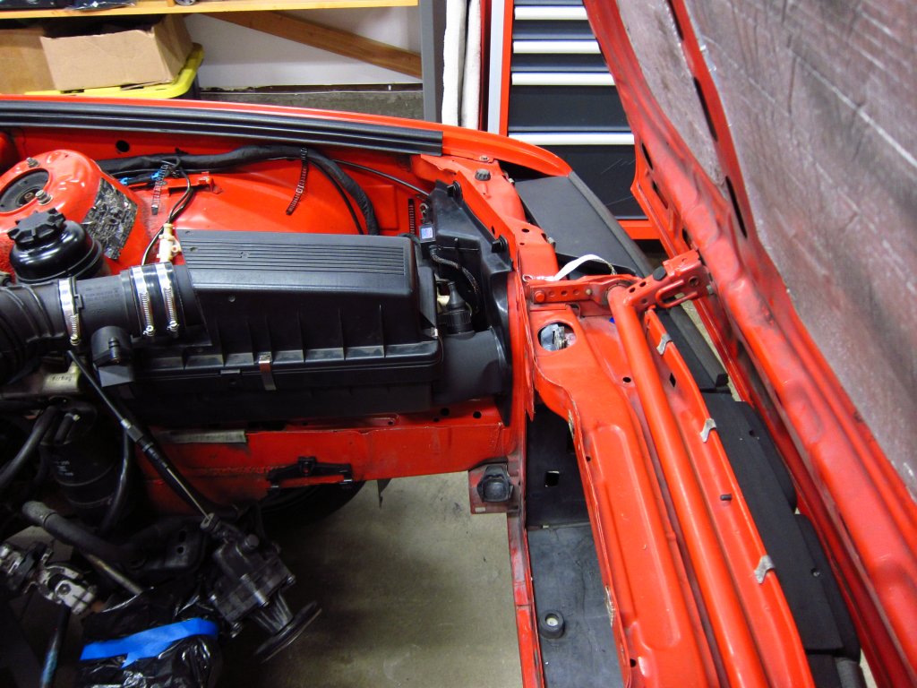
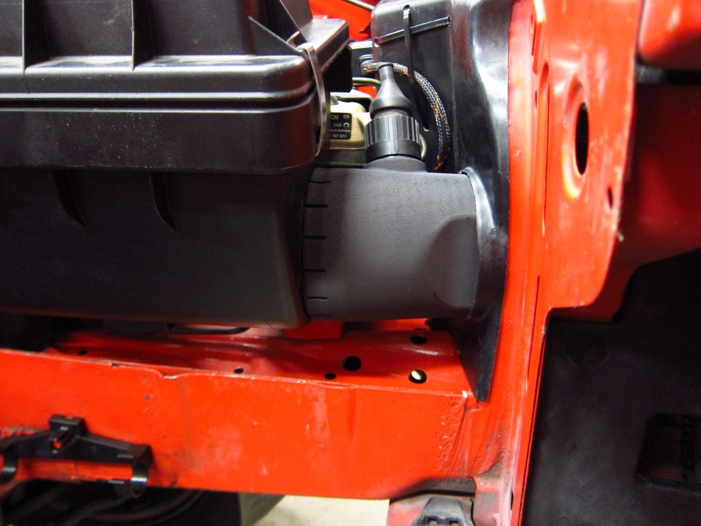
It is a tight fit in there, and the adapter has to slide into the headlight cover about an inch in order to allow the air box to be installed / removed.
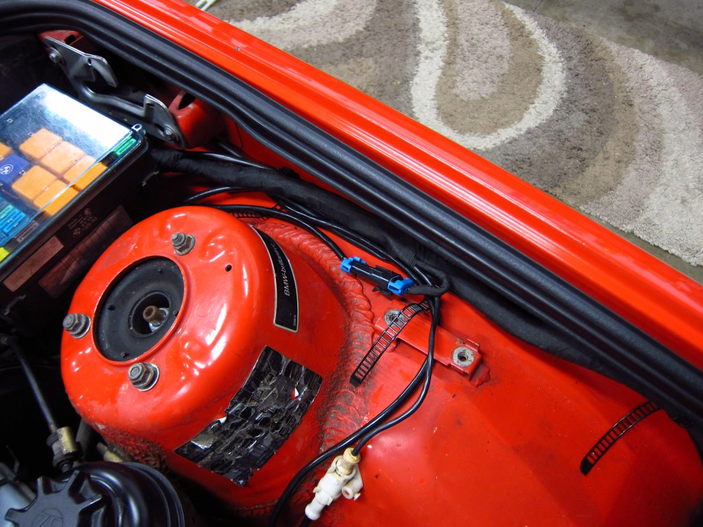
Let's see, other odds and ends. My HID igniters used to be zip tied onto the body brackets where the airbag impact sensors were, and it looked sloppy. Now they are mounted to the headlight covers, which is still a far shot from OEM, but it is a hell of a lot better than before. Space is very limited on the driver's side, so the igniter is on the front side of the cover between the low & high beams.
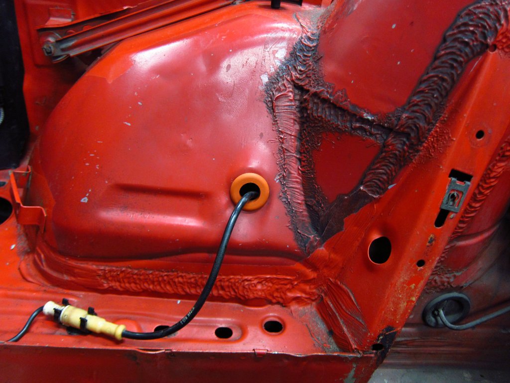
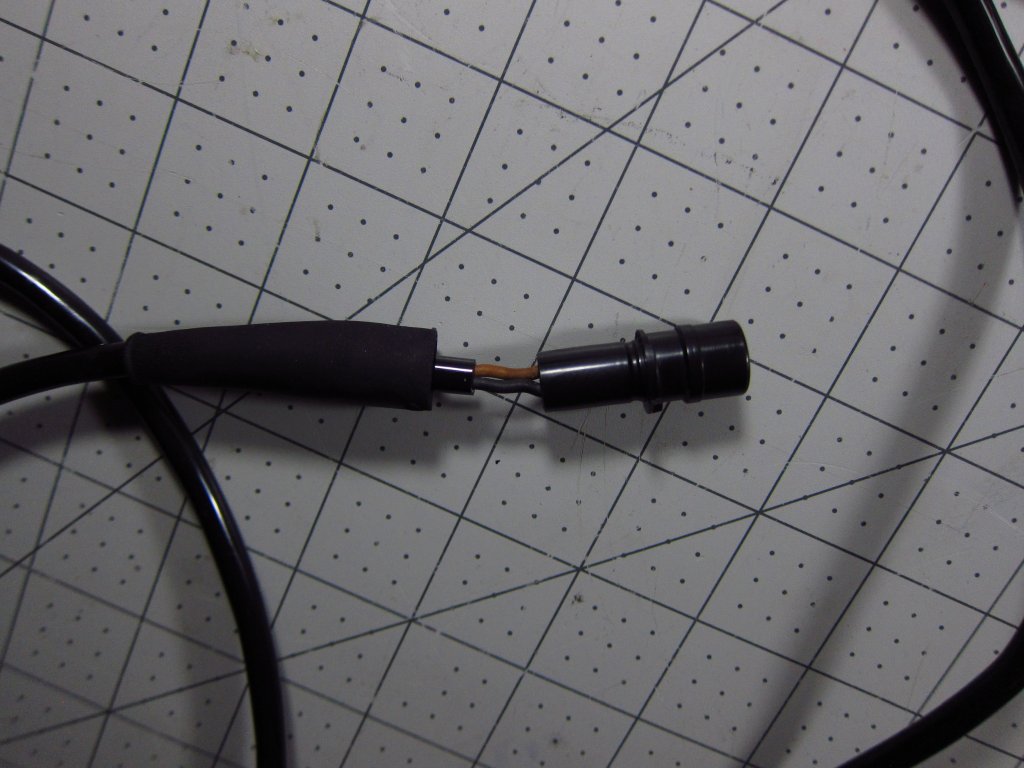
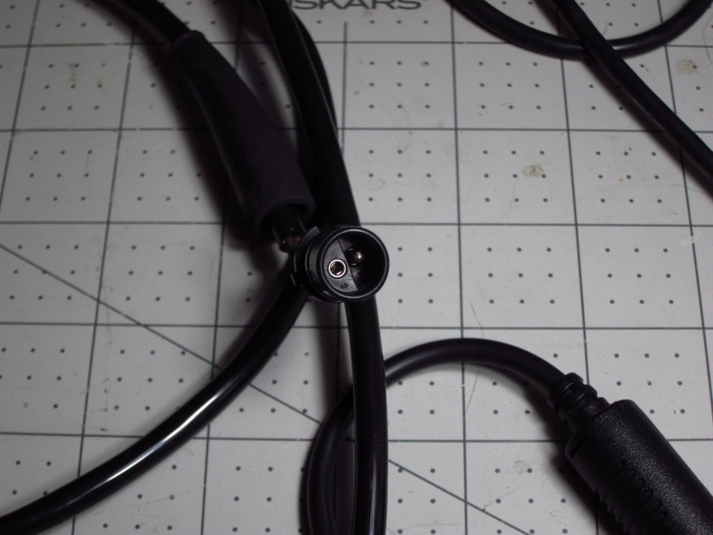
Here is the connector that splices in the replacement brake pad wear sensor cable. I left a LOT of extra length in it (it loops up by the fuse box and then back down) just in case I need to do future repairs, or I decide to re-route it someday.
Also, I replaced the decaying grommets in the holes that the ABS sensor and pad wear sensor cables pass through. There are also McMaster parts (1061T67), made of high temperature silicone.
Now I just need my balance dflywheel & PP back. I will be starting to bolt on accessories and brackets to the engine in the meantime. This project is finally starting to feel like it is moving!Leave a comment:
-
Forgot to mention this earlier, but watch out for Taiidan ambushes!
Didn't know that you'd gone to an M30 airbox, nifty idea.Leave a comment:
-
OK, update time. It has been a little while.
First, the flywheel and pressure plate are still at the machine shop for dynamic balancing. Those should be ready in a day or two, and are really the only things left holding me up from reinstalling the engine.
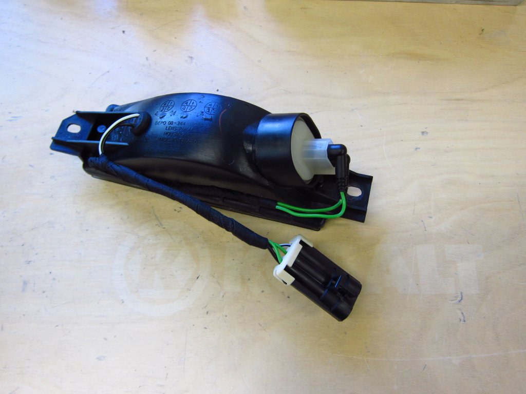
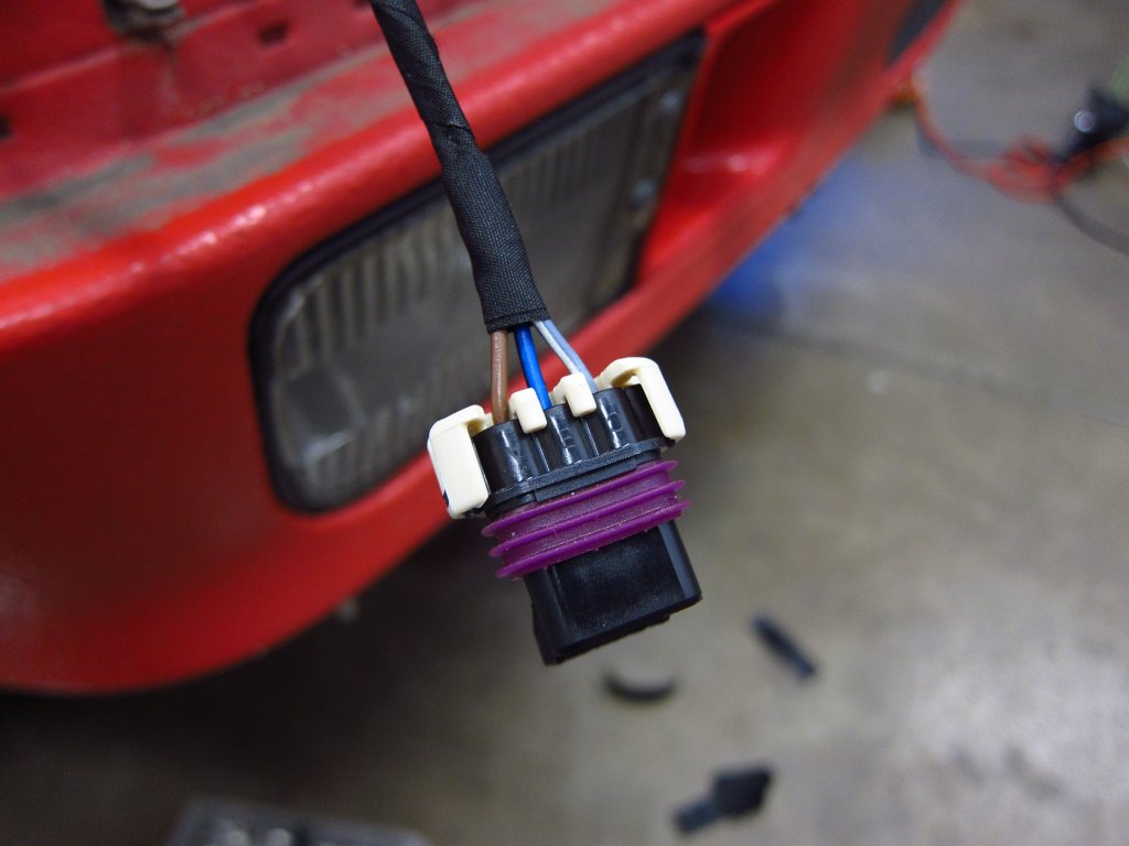
Beyond that, I am basically done with all of the chassis electrical repairs and mods. I put the battery in today and tested out everything up front. Since the connector housings for the front bumper indicator lamps turned to dust, I mixed up the wires for the parking lights and turn signals, resulting in a fast-blink behavior. When I pulled the bumper to fix the oops, I recalled that I had some new indicator housings (bought 3+ years ago lol) in a storage box. It turned out that they were Depo smoked Euro units which are not plug-n-play, but super simple to get hooked up compared to the rest of the stuff I have done recently.
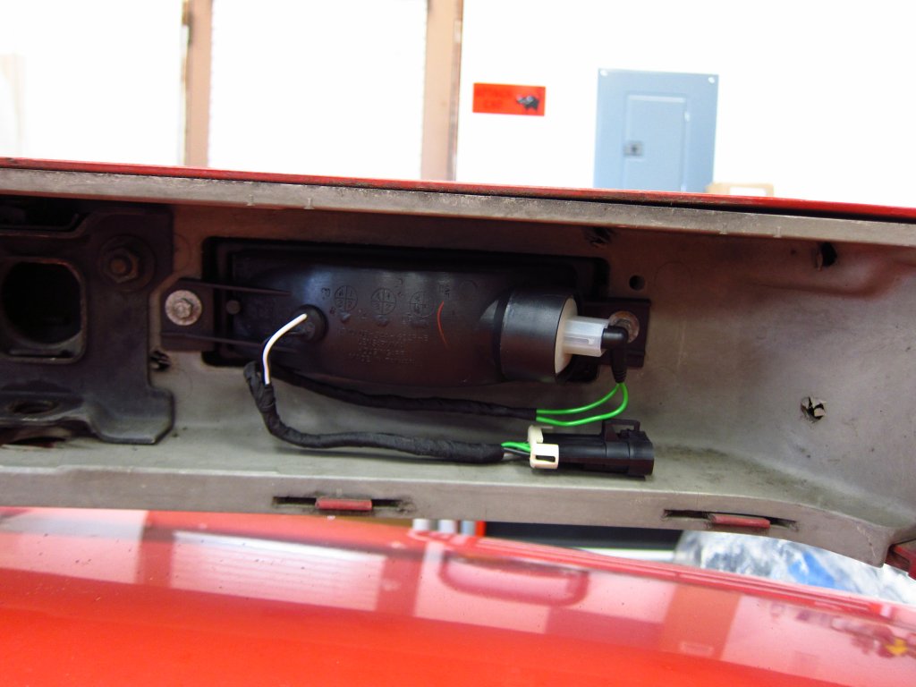
The units do not come looking like this. They only have the black + white wires sticking out, and an empty receptacle for the turn signal. However, the US version just uses a 3-position plug. I had a bunch of the repair wires with the rubberized 2,5mm round terminals, so I built a new sub-harness with those and wrapped them with the same Tesa tape I did everything else with. Connectors are Delphi Metri-Pack, which I m sort of regretting buying so many of because they are a little bulky. Oh well, they are economical and easy to work with. The new connection to the main harness just nests neatly up inside the bumper, and the extra stiffness from the tape wrapping keeps wires formed into place pretty well.
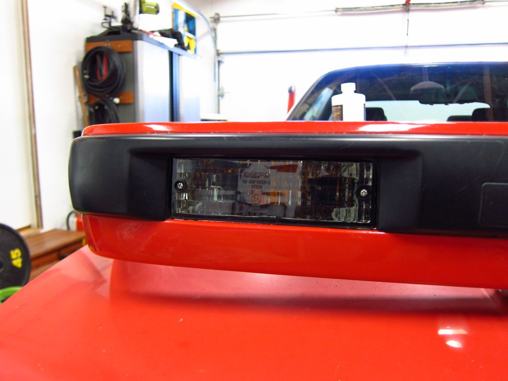
Overall I think that they look a lot better than the hazy 30 year old ones. These use amber-tinted bulbs.
I got the sound system power wiring in the trunk done as well, with the fuse holder bracket thingy just finishing on the printer this evening. When I get that installed tomorrow I will snap some pictures. Other stuff that I finished and didn't take photos of yet include the pad wear sensor cable and mounting all of the HID ballast stuff on the plastic baffles that conceal the headlights in the engine bay.
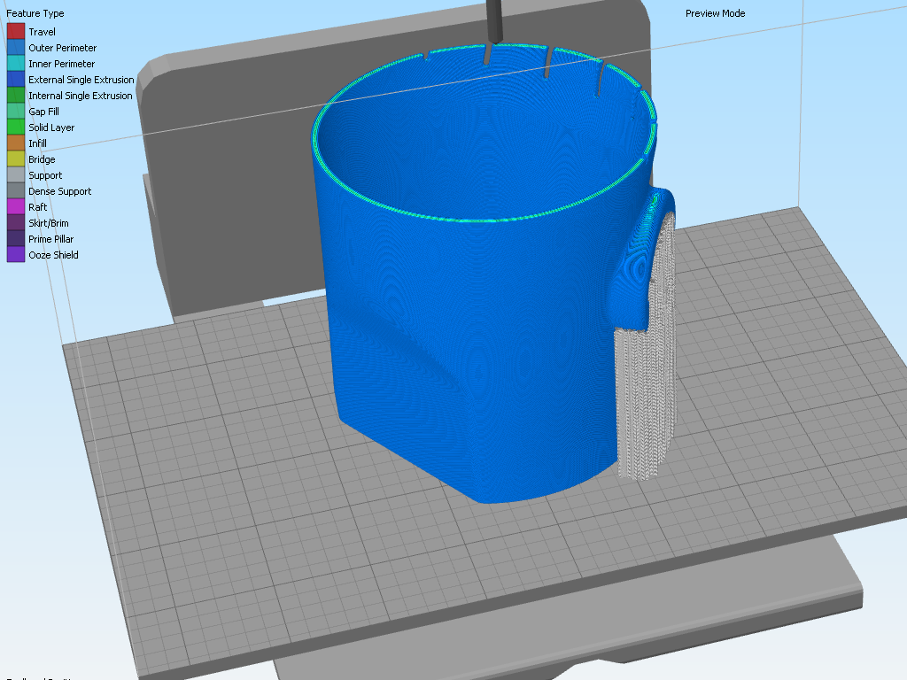
Also, I came up with a better air flow adapter to link the M30 air filter box (65% more filter surface area than stock M42) to the baffle behind the headlight. I went through 5 revisions on my 3D printer, and had the final one fired off in SLS Nylon. The PLA parts out of my printer will not hold up to the temperatures under a hood (you need to keep them under 60°C to avoid creep and sag), whereas the Nylon will have no problems.
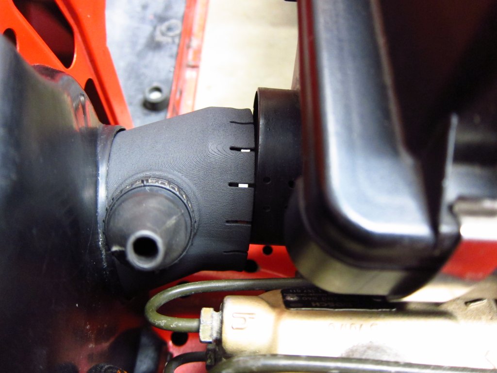
The M30 air box inlet is to the side and above the opening in the headlight baffle, and the metal radiator support sort of gets in the way. It took several tries to get the dimensions exactly where they needed to be. Installation with the air box is a little tricky, and I had to design the adapter so that it would slide ~2" forward into the baffle when installing/removing the air box and then slip out and onto the inlet. I also moved the air temperature thermistors for the ECU and my MAF converter into this tube, rather than just being zip tied up inside the filter box. They were crimped into terminals and installed into the spare 4-position round connectors I have left (the same one used for the O2 sensor). In the future I will probably fully move the MAF converter inside of the Motronic case and put the thermistor into the MAF, but that is a different project for a different day. I'll get some shots of the finished part and connector arrangement in the near future.
Leave a comment:
-
A big box of goodies from Tischer / BMW of Silver Spring showed up today, so I have almost everything that I need to put it all back together. Before I can do that though, I need to take the flywheel and pressure plate to the machine shop for dynamic balancing, so I assume that next week will be when I start turning wrenches in earnest. I think that I will mostly leave the accessories and stuff not bolted on to the engine just to make it a little easier to shoe-horn back in to the car, and the same goes for the engine wiring harness. Having that and the firewall cable tray out actually gives me that last bit of clearance that should make the reinstall a breeze (it often hangs up on the cable tray & wiring umbilical when those are present).
Thankfully, the M42 engine mounts that I got were manufactured correctly, so there is no need for poly ones. Maybe BMW Canada has different suppliers or it was just a bad batch or something.
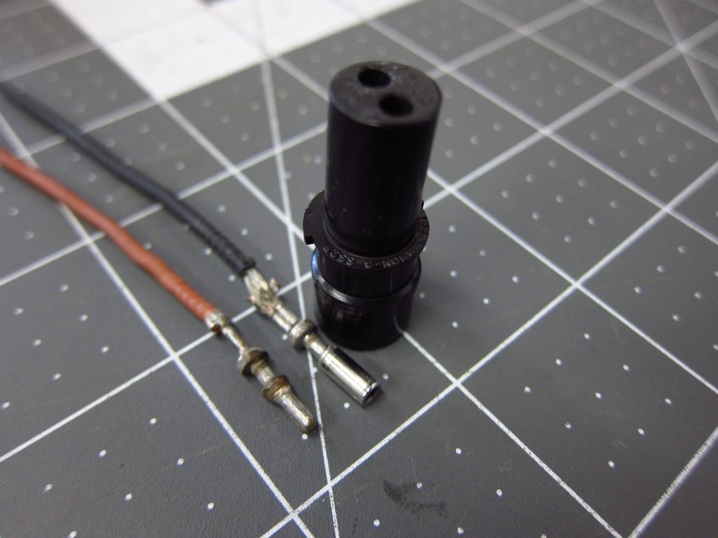
Also, I put the pad wear sensor connector back together this evening. These connectors are a big pain the ass. If someone wants the step-by-step instructions I can type them out, but the short story is that these are one type of connector that you sort of want the specialty tool for. I managed without it, but it involved unconventional assembly. The terminals are an interference fit inside the rubber housing, and you have to push them really really hard to get them buried all the way up where they belong. I fed the wires through, crimped the terminals on and then forced them in from the front since the forward part of these things is a hell of a lot more sturdy than the part that the wire is crimped onto, and I used isopropyl alcohol as the lubricant per the manufacturer's recommendation. Naturally I forced one too far, and I ended up brute forcing it into place with some very small needle nosed pliers from the back side.
In other news, I ripped out all the power wiring for my sound system and redesigned how I want it all to route. Everything worked fine before, but there was a jumble of fuse holders and wiring next to the battery which I disliked. I'll detail the new wire routing scheme in my car audio thread, but basically it will all run along the driver's side fender in the outermost bulkhead cavity, with a 3D printed fuse holder mounted to the gas door lock solenoid bracket. This way everything will tuck up inside behind the side panel covering, guide the cables and eliminate the mess that was by the battery (I did the sound system & wiring back in 2008/9 and was a lot less competent then).
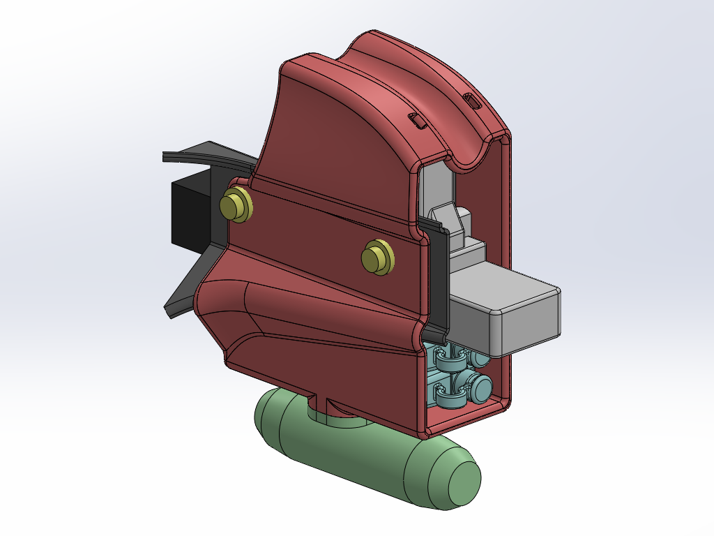
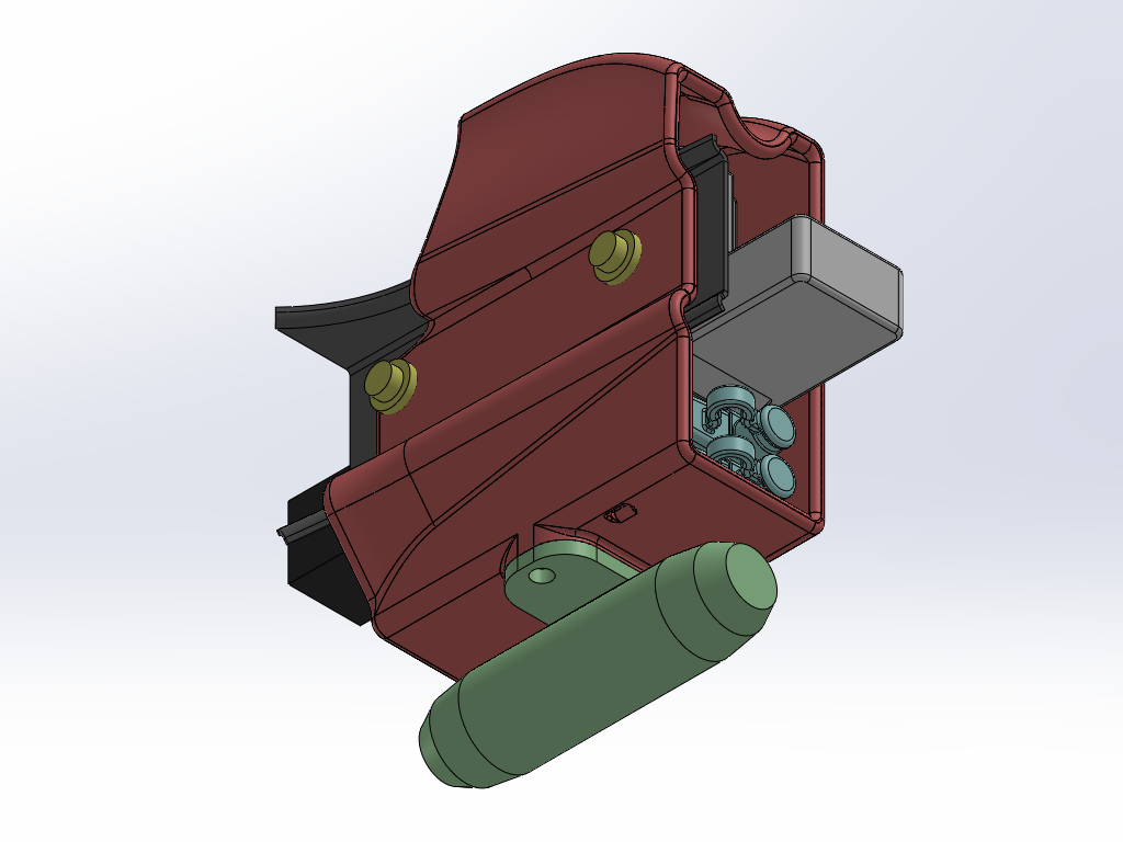
The first version is in the printer now. The new fuse holders and power cable are coming from Parts Express, so I made models based on the existing stuff. An hour or so with calipers was all that was needed to get the lock solenoid and its bracket modeled well enough to work with. Once I get the actual stuff I will update the base models, and it should all regenerate properly since the big holder/bracket part is fully top-down parametric with the stuff around it. At ~7.5 hours per print I'd prefer not to have to tweak the design more than once or twice.
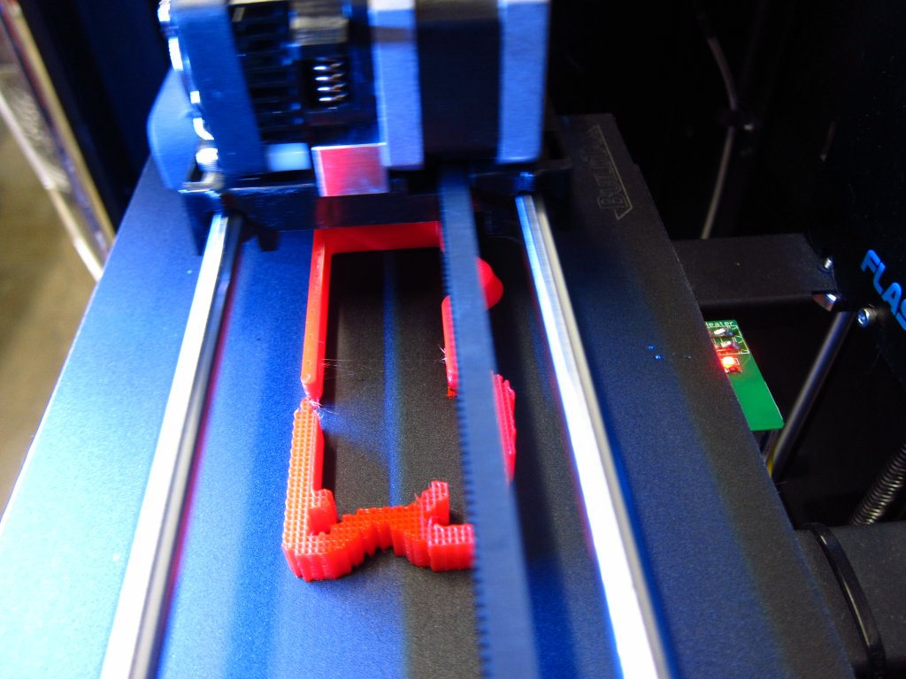
The big green fuse holder has the 60A fuse for my 5CH amplifier, and the 2 smaller teal ones have 5A fuses for my 3-way active crossover and the RMT-200 head unit (I am running dedicated power & ground to it all the way from the battery since the factory power & ground are not entirely optimal). The red bracket ended up looking like a space ship from the original Homeworld games IMO.
I spent a bit of time in Simplify3D getting the slicing optimized for the part. My printer is a Flashforge Creator Pro that I have modified fairly extensively (removed second extruder to eliminate vibration, installed TMC2209 stepper drivers for smooth silent operation using custom designed PCBs, designed a clip-on dial indicator holder for precision leveling, used brass shims to remove guide rail slop at ends). It is a decent printer out of the box, but it is a lot better now with the changes and a couple of days spent optimizing the print settings with some test pieces.
Anyway, I will continue updating as I make progress, whether it be with the actual original topic of the thread (getting the stupid thing running) or other too-much-time-on-my-hands nonsense.Last edited by bmwman91; 10-14-2020, 09:33 AM.Leave a comment:
-
I received the replacement connector housings and cable straps today, so the front chassis wire harness is now reinstalled and looking good. Everything looks a hell of a lot cleaner all wrapped up, and the headlight wiring is vastly better now with zero splices or other BS in it. Both the igniter and ballast are now mounted cleanly on the passenger side light cover / panel, and I will look into doing the same on the driver's side (it is currently mounted where the airbag impact sensor used to be).
Does anyone know the PN for the 3-pin connector housings for the front bumper indicators/signals? The only 3 position connector housing I can find on RealOEM is not the correct one (it is the one for straight weatherproof 2.5mm receptacles, and is used on the aux fan plug), but I can't locate the one for the 90 degree terminals used in the front indicators and radiator temperature switch.
Also, does anyone know the PN for the circular grommets that go into the holes in the wheelwells where the ABS sensors and pad wear sensor cables go through? Both of mine disintegrated and I can't find them in RealOEM.
I also spent a little time scrubbing the exhaust heat shield clean and a few other odds and ends, but there is not much else that I can do at the moment. So at this point it is just a waiting game for the rest of my parts to show up. I'll run the flywheel and pressure plate up to the machine shop this week for balancing as well.Leave a comment:
-
Small update since I only played around for a few minutes today with the replacement cable for the brake pad wear sensor. The old rubber boots and grips were easy enough to remove from the old cable, and I slid them onto the old airbag sensor cable in approximately the right positions. For reference, Windex works super well for getting things like this to slip easily, also when trying to push wires into PVC sheathing. I got the contacts out of the old connector body and determined that I was not going to pry the crimps apart and reuse them (I tried and destroyed one). However, these things are still in production and readily available, so I will just order up new terminals and crimp them on! Now I get my nice factory-quality replacement cable, which I will join with the main harness with a Metri-Pack connector.
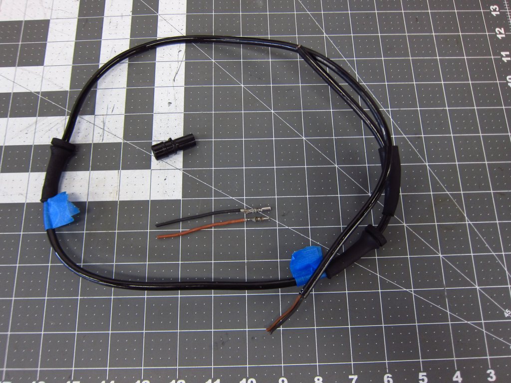
For reference, the manufacturer is ITT CANNON, it is part of their Sure Seal connector system, and the relevant part numbers for this are:
120-8552-000 - 2-position plug housing (harness side)
120-8551-000 - 2-position receptacle housing (pad wear sensor side)
330-8672-001 - Male crimp terminal (pin, one per connector side)
031-8703-001 - Female crimp terminal (socket, one per connector side)
317-1398-000 - Rubber boot (used only on the harness side, but would fit either)
Mouser, Newark and other online electronics suppliers seem to carry most or all of these items. The manufacturer's catalog is here (note that there is also a Mini Sure Seal series which is not the same):
https://www.ittcannon.com/Core/media...g.pdf?ext=.pdfLeave a comment:
-
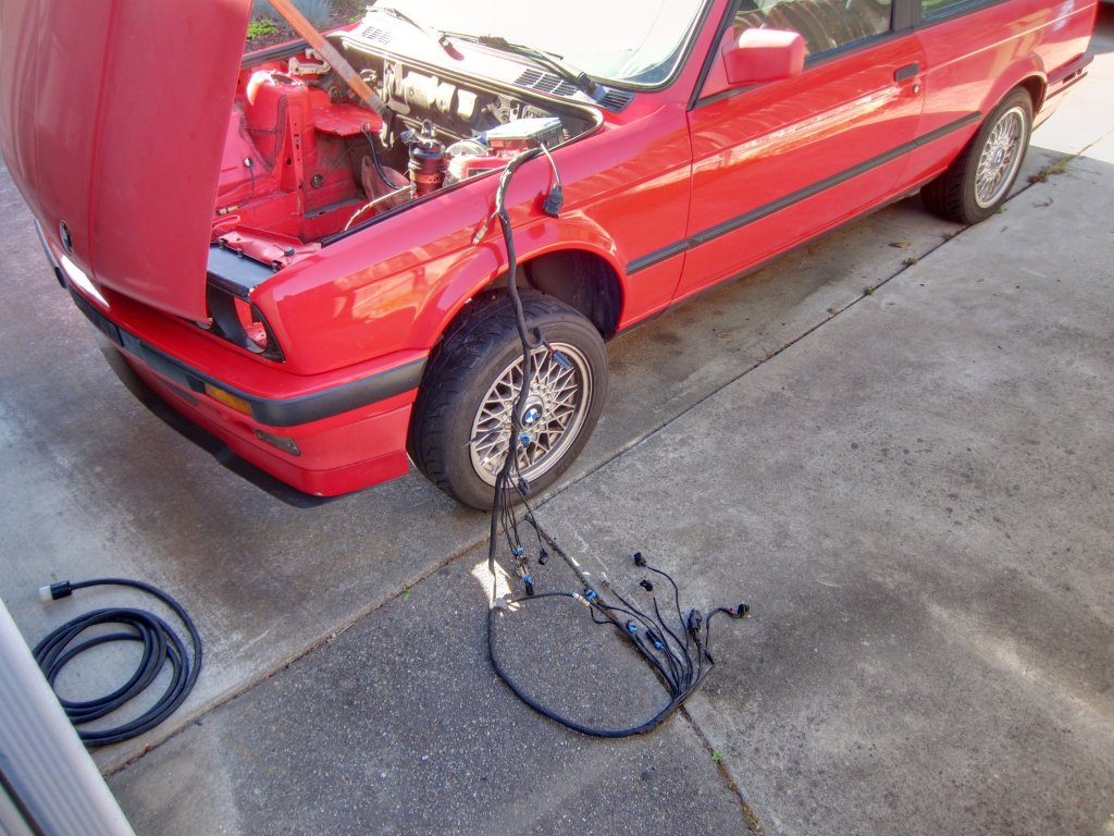
Phew, I got the front harness all done today. I should have put on some sun block because I am medium rare lol (I am currently working on the car in the driveway despite my garage being nice and clean, because idiot).
I think I spent about 5 hours on it today. All wires were wiped clean with 99% isopropyl alcohol and/or Simple Green. Thankfully the only sticky goop was in the few small places where BMW used electrical tape, which the alcohol took care of pretty easily. As anyone else who has looked at their wiring knows, the fabric tape basically disintegrates as soon as you touch it, so all I needed to do was wipe the dust and dirt off of the wires after getting the shreds out. There was one change that I made to the thing. For whatever reason, the horns are on their own sub-harness with clunky spade connectors to split the single power-in line to the two separate horns. I chopped out the connectors and joined the horn wires with some perma-seal butt splices (crimps with heat-shrink shells that also have hot-melt glue lining) plus some adhesive lined heat shrink tubing on top of those. They were then fully integrated into the existing main loom, and the horn leads exit with the rest of the lights' pigtails.
As far as order of operations
1) Measured where all of the junctions were before unwrapping things
2) Removed all the old crap on the passenger side and cleaned that half of the harness
3) Wrapped all of the individual pigtails about 2" past where they would exit the main loom
4) Wrapped the passenger side half of the main loom, stopping about 6" from the exit point for a bunch of driver's side stuff
5) Unwrapped the main loom to the point where the ABS leads exit and cleaned everything
6) Wrapped the driver's side pigtails with the same ~2" of overlap
7) Rearranged a bunch of the ground leads feeding into the big splice so that they were no longer overlapping and folded-up inside the loom
8) Removed the rest of the old cloth tape all the way back to where it ended ~16" from the fuse box and cleaned things
8b) BMW wrapped a good 16" of the loom coming out of the fuse box with electrical tape. I assume this was to ensure that any water that spilled around there would not wick into the fuse box. Since it was well intact still, and access to things around there was very tight, I opted to wipe it clean and leave it in place. Sometimes "if it ain't broke don't fix it" is the way to go
9) Wrapped the ABS pigtail (it is one stiff piggy!) while more or less keeping it in its final curved shape
10) Wrapped the main loom starting where it exits the fuse box (so, Tesa over old electrical tape) and worked my way all the way back to where I had stopped from the passenger side, giving it a good 4" of overlap
11) Reinstalled it to make sure that it actually fit properly and all of the leads reached where they needed to (they did, thankfully)
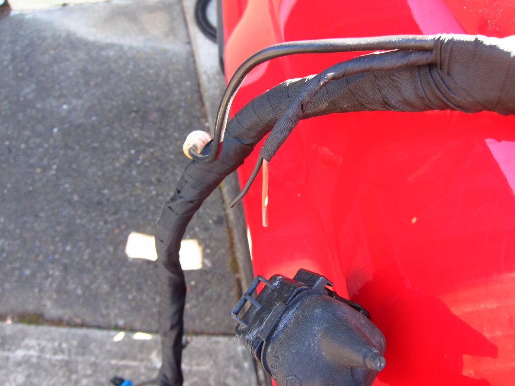
The harness was (as expected) a bit stiffer than before with the new Tesa tape, but it took up its old path fairly easily. If anything, it seemed to be a bit longer than it used to be and I really had to work it into the front left corner to push the ground strap back so that it was not too far past the ground lug stud. Better a little too long than a little too short, though! It turns out that I was also missing a cable strap thingy, so the harness is actually supposed to run high up to about the ABS unit, and then go straight down and then forward again. Since the strap was missing I had the thing running more along the hypotenuse of that path, hence the slack. I have a pile of new cable straps coming, as well as half a dozen new connector housings since a bunch of them totally fell apart (windshield washer, both horns, radiator thermal switch, both front turn signal/indicator lights). All of that stuff can be addressed later though, and does not require me to take the harness out again.
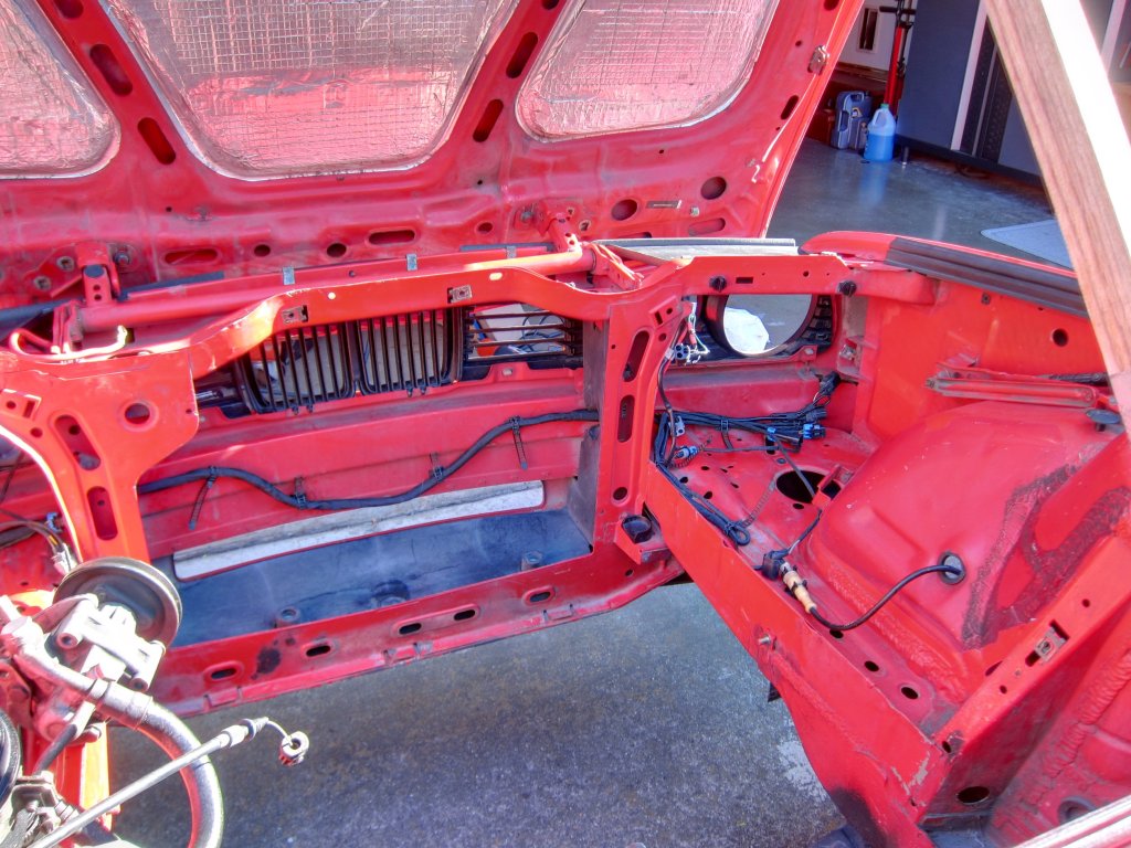
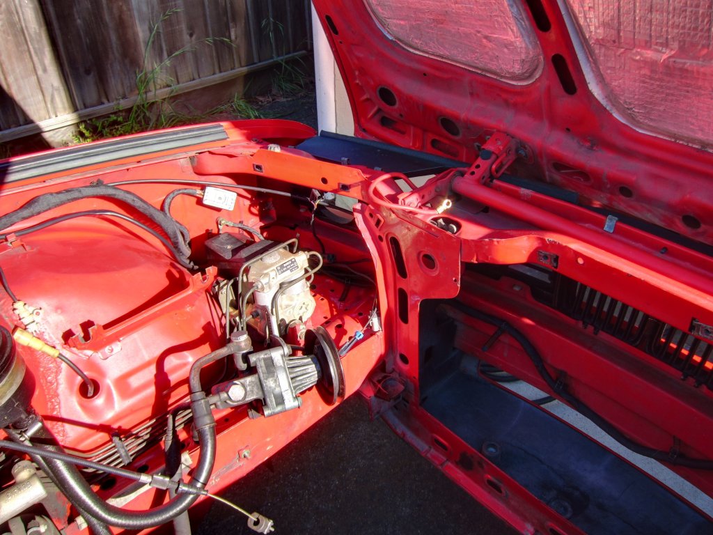
OK, talk is cheap and I am typing too much again. Here are some pics of the results. Not perfect, but a hell of a lot better than before. Wrapping those little 2- and 3-wire pigtails is a pain in the ass.
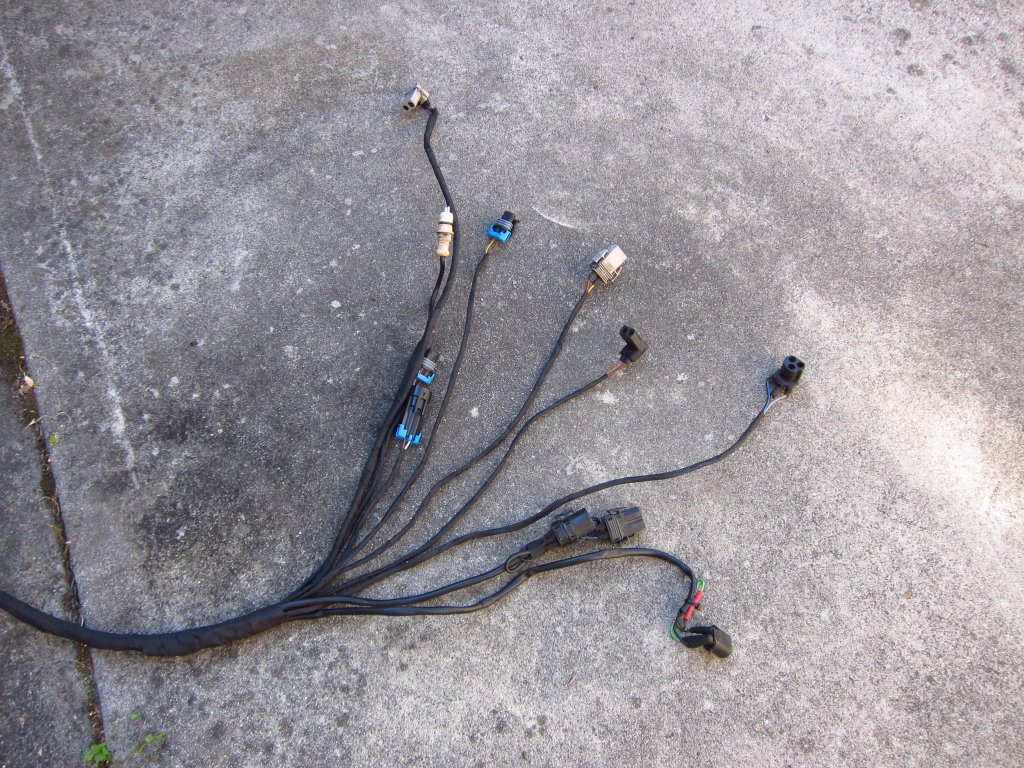
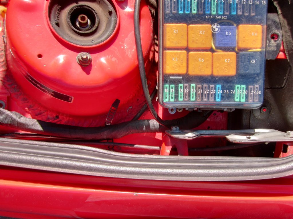
As I noted above, I left the original electrical tape on the ~16" it was covering after the fuse box since it appeared to be in good shape, but I did also wrap over that with new Tesa tape as well.
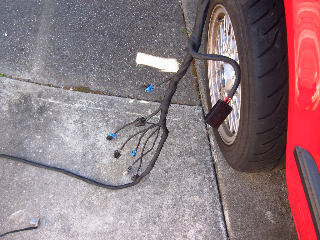
Here it is roughed-in to the car, waiting for new cable straps and new connector housings.
So there it is. Overall I think that it went faster than expected. I was sort of sweating this last night and this morning because it seemed a bit daunting, but once I got at it things just sort of flowed into place. Really, the big trick in my mind is cleanliness. Get those wires clean and spend the time to wipe them down well (or scrub them with alcohol as the case sometimes is) or else the tape will not work out well at all. Also, wear gloves. The sweat and grease from your hands will lead to poor results. All of my harness refurbing (engine and chassis) have involved wearing gloves the whole time. On top of getting the tape to work properly, it also saves you from the black goop from the old tape, which is a giant pain in the ass to get off of your skin (unless you like using acetone and a scouring pad on your skin).
Tomorrow I will reinstall the headlights and verify that everything works properly up there, as well as figure out how I want to repair the brake pad wear sensor harness (which I just remembered I chopped off when I previewed this post lol).
But, being a fiend for punishment, part of me wants to hunt down a 325iS with a fully intact chassis harness and yank the whole thing out for refurbishing and then install it in my car. I have always wanted to have a 318iS with the full check panel, because nostalgia, and the only way to have it is to swap the whole electrical system. A big inspiration for the harness work I have already done has been Jordan's INSANE full restoration project (here). While everything I am doing is Mickey Mouse in comparison, it at least gives me a reference for a lot of things. Seeing the whole electrical system out on his floor basically made me think that it is not all that awful to deal with. These cars really are sort of simple, electrically. Based on my experience, the only really big pain in the ass is the dashboard (I swore I would never remove one again when I put my crack-free one in a few years ago), and MAYBE the big plastic side wall liners in the trunk. Other than those items, I can gut the interior of my car in ~30 minutes since I made the cuts in the carpet around the heater core, which I should probably replace anyway.
There I go again typing too much. Typing out everything I am doing is my way of reflecting on the day I guess!Last edited by bmwman91; 04-28-2020, 10:44 PM.Leave a comment:
Leave a comment: