-
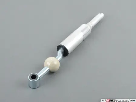
Thank you! My lever placement is pretty good but after trying a few different shift levers (E30, E36, E46...) I could use something with a little more length below the ball to shorten up the shift action and I think the S-bend will position it even better in the chassis.
MJ -
Thanks! The shifter is the E90 330i one (25117551645) so it's the stock shifter for this transmission. It's a mostly straight shifter with a slight S-bend at the base. I figured I'll use this as the base line and see if I want to make any changes once I get to drive the car.
Leave a comment:
-
Making a lot of progress and looking great. The attention to detail on all of the sound deadening is fantastic...it may all be hidden but you know it was done right!
Maybe I missed this in an earlier post - what shift lever did you end up using in your custom carrier? I see a BMW part sticker but can't make out the numbers.
MJLast edited by mjweimer; 07-15-2020, 02:49 AM.Leave a comment:
-
Lately I've been able to work on the car much more and it leads to satisfying progress. The engine bay plumbing is 98% ready. Actually all that's missing is the heater core and the air mass meter. I've misplaced the O-ring and the small screw-on tabs that connect the air mass meter to the filter box so I need to find them before I can finish that. In the cabin I got all the wiring sorted that lives under the carpet and got to install the carpet as well as the sound damping under the headliner. Big thanks goes to a fellow E30 builder who took meticulous photos of all the body wire looms as I never had half of these wires before. It seems the car has bee broken into sometime in the past as the locks don't match. I'll replace all the locks with a uniform set. I think someone has already tried to remove the ignition lock and failed because it turned out to be impossible. Probably the release mechanism is somehow mangled so I needed to replace the complete top end cast of the steering column. Lucky that I have a pretty wide range of E30 spare parts.

Before putting in the carpet I wanted to glue in the sound damping for the headliner as not to smear any glue on the carpet. The C-pillar foams had deteriorated with age and crumbled to dust. I also had had to remove some of it from the driver's side to fix a rust spot. You can get a new part for the passenger's side but not for the driver's side so I had to make that myself. It was pretty easy when you had the other side part at hand for reference. The part comprises of self adhesive bitumen board (or whatever you call it) with a layer of foam glued to it. For my own I used rubber cork board as the base as that was the closest equivalent I could easily find.


I used 3M adhesive spray for foam and I must say it's very nice to work with. I used the same stuff to glue the original sound damping material to the ceiling. There's really no off spray and it's accurate to use so depending in the spot there's not much need to cover up anything. Only thing is that when you spray overhead, small glue droplets occasionally drop down so you need to take that into consideration.


The rubber cork board wasn't self adhesive so I used brush on contact adhesive for that.


When the ceiling was done I got to work on the floor. Before putting in the carpet I decided to add the air channels for the rear passenger leg room. All the E30s come with an option to add then. (well I don't really know about the oldest prefacelifts). The hvac box has plugged outlets for these channes and the sound dampening under the carpet has pre-built slots for the channels. They are just filled with soft foam.
Air Channels:

Outlets in the hvac box (broken non-ac model, not to be used)

The underside of the carpet. Dark grey foam needs to be removed.


The car feels so much readier with the carpet in. And it really was a pretty big step in reality as well considering everything I did before installing the carpet.Last edited by Skarpa; 07-14-2020, 09:10 AM.Leave a comment:
-
It's been a month since last update and the project has progressed somewhat slower than I'd like. But today I reached a small milestone and got the engine bay brake pipes bent into shape. I have kinda subconciously avoided the job and I'd say rightfully so. Along with the brake pipes I have the power steering and hydro boost plumbing mostly ready. I made a cooling loop for the power steering fluid. Earlier I made turned some hose connectors for it in lathe.


The loop is not in the most direct air stream. If there's any problems in keeping the fluid cool enough I'll try dropping it lower to be more in line with the air openings for oil cooler. When the cooling loop was done I got to work with the brakes. I wanted to make sure my ABS pump is in working order so I took it apart to check the insides. Porsche 968 shares the same ABS pump apart from hydraulic connections so there are good instructions for taking it apart here:
http://www.porsche968uk.co.uk/techni...abs-refurb.php
Everything look nice and clean so I didn't take apart the solenoids. I assume they are mechanically ok so after good cleanup I put the pump together.


Now it was time to bend some brake lines. I did the lines out of copper-nickel partly because I was short of one steel line and partly because I wanted to train using easier and cheaper material. I turned out to be a good idea because it took three tries to get one of the pipes right.


Surprisingly big job. Now that they are there I have no particular interest in going through the same stuff with the steel lines so these may well be the final product. Unlike the stock system, I routed the pipe for the right front brake through the nose of the car mostly because the firewall area is aleady so cluttered but also because it interferes less with dropping the engine and is probably shorter this way. I put a heat protector sleeve on the line where it's closest to the exhaust manifold.Last edited by Skarpa; 06-30-2020, 06:44 PM.Leave a comment:
-
Thanks for the tip. I wasn't actually aware of that shape of plastic. I knew there was the M3 plastic cover:
And the M40 engine version:

1714106 is the plastic mold number for the part you posted. After a bit of research the actual part number seems to be 12521714106 and it was used in US 318i and 318is and the European 324 td. It might be better shaped for my purposes than either of the above but it would still require modification so I'll stick with the 3D printed part. But thanks for the tip. It was interesting to learn about that and if there was no 3D printing possibility, I would be thrilled about that. I've done a bit more consulting about 3D printing and in case there's problem with the filament printing, I can easily have the part made with laser sintering technology for pretty cheap.Attached FilesLast edited by Skarpa; 06-01-2020, 09:27 PM.Leave a comment:
-
-
BMW made a part very similar to the one you are making. Have you tried it already? Part #1714106
Edit: There is one in Slovakia ebay right now for $29.00.
https://www.ebay.com/itm/BMW-e30-pla...UAAOSwdTRexkuqLeave a comment:
-
I increased the thickness to 2 mm and added stiffening ribs to the part. It's now in the process of being printed.

Leave a comment:
-
-
Well, damn. But that makes alot of sense. Thanks for the insights. I guess I'll need to consider laminating the piece over foam mold or something like that. The foam tape is self-adhesive closed cell tape made of soft EPDM. It's a pretty universal product with different companies making similar products.Leave a comment:
-
3D printing probably isn't the right process for that piece. It being a thin and complex part there's no way to print it that will take advantage of the material's strength, and layer adhesion will always be a factor no matter which orientation it is printed in. It'll work it would just be a lot of print time due to support requirements and the part will probably be fragile and prone to warping. What's the foam tape you have between the radiator and core support? I need to get my hands on some of that.Leave a comment:
-
For a while I've been working on small but important stuff that doesn't leave much to show. Let's make an update now that I have a bit more visible work done. I centered the rack, installed the steering column and dialed the front wheels straight.

The gap between the left side of the engine and the body is narrow and will be full of stuff so I had to start filling it from the bottom. I don't want to remove the plenum because that would be a big job. Next I installed the fuel lines and the filter. I had to drop the gas tank enough to swap the pressure and return lines. This way they are located better in the engine bay. Next I installed the pedal assembly and the brake master cylinder and the booster.

When the clutch master cylinder was in place as well I got to plumb it. The local hose store had brake fluid proof hose only in eye-aching green so put a wire loom sleeve over the hose. It actually gives kind of a stock look since the original clutch hose is a braided one.

Now that I had the brake master cylinder in place I checked that the intake rubber boot fit in place and guess what: It didn't :( I was missing a couple of centimeters of space. Honestly I don't remember if I had the engine tilted slightly to the passengers side when mocking stuff up or if it's a case of the plenum being slightly differently positioned now that it's on the official mounts. I'm leaning on the latter explanation but that doesn't really matter. Now I had to put 12 mm worth of spacers under the left engine mount to tilt the engine away from the brake master cylinder. When jacking up the engine I tried to observe if there's any visible change in how the prop shaft lines up but I almost couldn't tell the gear box was moving so I'm not too worried about that. If the prop shaft vibrates or starts chewing guibos, I'll get back to that. To find out if I have any other fitment issues, I assembled all the other major components in the engine bay at once. The AC condenser and the electric fan found their way to the nose of the car.

Then I mounted the air direction plates around the radiator. I think the plastic directly in front of the radiator is from a 318 is with AC but it had to be cut up a bit since the E36 328i AC radiator is taller.


Only the left vertical section of the plastic was used. I added soft sealing strips around the radiator to direct all the air flow through the radiator.

The plastic side plates in front of the radiator are for an early model with AC. When the radiator was in place it quickly became evident that I had to change something. The magnet clutch for the AC compressor was basically touching the radiator. The Seals I had between the radiator and the body front frame were pushing the radiator back and worsening the situation so I had to mostly remove them. Although the radiator is so close to the body that there's not much space for air to flow around it even without sealing especially after i pushed the radiator mounts forward as much as possible. With these changes I was able to create a 5 mm gap between the compressor and the radiator.

That's slightly better but still not great. Someone with more experience could tell me how much the engine tends to move backwards and forwards in the engine bay. The radiator hoses didn't line up that great either. I can make to bottom one work but the top one is pretty sharply kinked and I'm not quite happy with that.

But regardless of those issues it was very pleasing to look at the engine bay with all major components in.


Next on the list there are the hydraulic hoses for the power steering and the hydroboost and making the brake lines to the ABS pump. There are various reasons why I haven't done that yeat even though it might have made sense but I should still be able to get all of them in.Leave a comment:
-
Thanks! I usually work on the project a couple nights in a week in it progresses steadily even thought there's sometimes regrettably little evidence for it. I usually like to make a post when I get something ready but here's a little post about a couple of jobs that have reached a kind of "done for now" state. The engine wire loom is 95% done. The last 5% will be completed when I have the heater in and can finally fix the blower motor cover along with the wire loom cover.

After taking this pic I trimmed off the unused diagnostic plug bracket and bent the fuel rail inlet into better direction. A while ago some idiot decided to redo the battery tray area so the M3 wiring cover end no longer fits so I had to come up with something else.


I'll need to have this 3D printed in some suitable plastic.
On a final note: Here's what I do now that I no longer have accessa to lathe and parts are NLA


Leave a comment:
-
Lately I've done lots of small but tedious work. I added the missing pieces of sound deadening to the engine bay. The material is the best I could find from a local store of technical rubber and plastic. It's self adhering damping mat with polyurethane surface. Time will tell how it handles the engine bay environment.


The stock sound deadening looks like it's hanging loose but it actually sits quite well when it's correctly in position. Here it's turned aside because I decided to add a couple of body studs to fix it better. They were the ones that are missing from early models. I also glued the sound deadening to the fire wall with contact cement.

Here's how the glued on body studs turned out. When gluing them on I also glued and riveted the ski door opening shut.

A friend of mine pointed out that because I hadn't cut slots in the top hats of the poly bushes, It wouldn't be possible to put a box spanner there to tighten the eccentric bolts. He also recommended flipping the bolts so the nuts are towards the center of the car because that makes it a lot easier to tighten them. The bolts need to be fairly tight to hold the adjustment. Luckily I didn't need to drop the whole axle assembly. lowering the subframe a bit was enough to flip the bolts. While under the car, I fabricated a small piece of heat shield between the two factory ones out of thin aluminum plate.


The shifter received a brand new rubber boot because to be honest, I've lost the original one. I guess it's for the best. I still need to fix the back up light wires to the shifter bracket. It would have been a lot easier when the transmission was still on the floor or at least before bolting on the prop shaft but you can't remember everything.

I borrowed cable terminal crimpers from a friend and started making the main power cable.

These would go all the way up to 120 mm2 but I settled for stock 50 mm2 cable (from an E36, mind you). At the battery end I used a fused battery terminal out of a Renault Grand Scenic. It just fits under the E30 battery cover when you leave off the lid of the battery terminal and trim a few ribs from the battery cover. The piece is a bit flimsy compared to BMW parts but I believe it does the job.


I tried to shield he cable in all the places that are in any risk of chafing. Although the insulation on the cable is very thick and sturdy to begin with.

The stock cable supports that fix to body studs are no longer available so I used Hellerman-Tyton screw on cable tie fixings instead (model HDM19). They are robust, screw on directly to body studs and look pretty tidy.

 Last edited by Skarpa; 04-19-2020, 10:32 PM.
Leave a comment:


Leave a comment: