-
damn this is cool. I definitely want to do something similar in the future. Nice work. -
That is super cool! Makes me want to learn more about finding electrical/computer solutions for problem solving.Leave a comment:
-
OK, as promised, here's the final photo dump of my finished successful project. It took me more than a year thanks to lots of other distractions and priorities, but I am super stoked that this is now done and working perfectly.
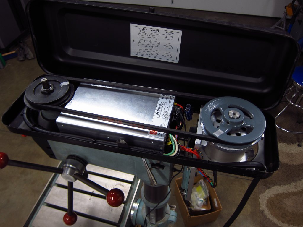
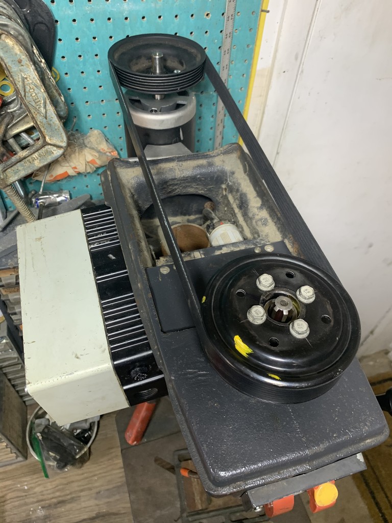
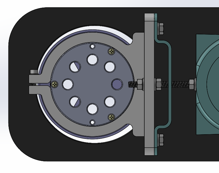
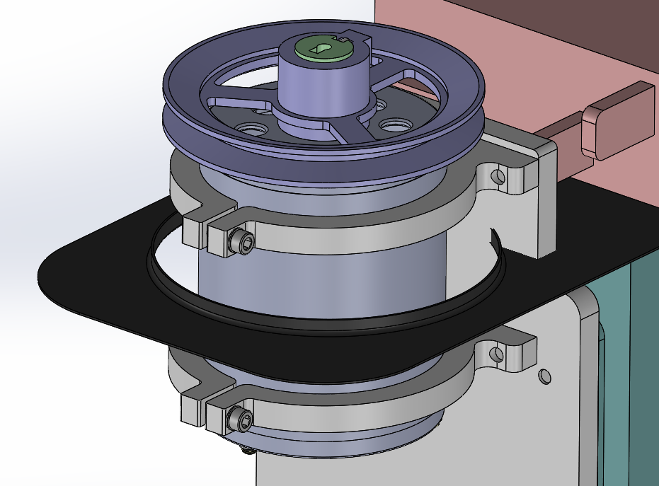
Here is how the 1500W PSU is nested into the belt/pulley housing. It is a tight fit, and the machining work that I did on the head casting was absolutely necessary. The PSU is screwed into the bottom of the housing in all 4 corners, so it isn't going to move around at all. I also ditched the cheap cast zinc motor pulley and went with a cast iron one...there was just way too much warp and runout in the zinc one. As it is, this relatively long V-belt develops a little whipping at specific RPMs as it hits resonance frequencies, and while those are easy enough to avoid, I think that I might design a bolt-on intermediate pulley to tension the middle of the span. Or maybe I will just leave well-enough alone.
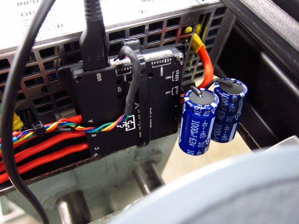
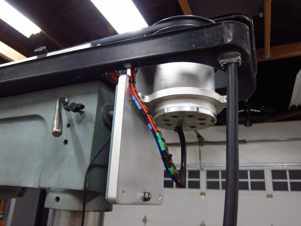
Here is the ESC (MakerX Mini-FOC Plus - a VESC clone) mounted directly to the PSU with minimum power lead length. This thing can draw significant current with high frequency spikes, so it is critical to keep the input leads short, and I had to add a couple thousand microFarads of capacitance to really clean up the power rails in the thing. I hacked up the ESC quite a bit to directly connect the caps to the input pads, and to replace the output leads with 4mm^2 power wire from an old M42 engine harness lol. Around this time was when I was also rebuilding the engine & front chassis harnesses on my E30, so I was all about clean wiring and using Tesa harness tape when possible lol. The motor mounting came out super clean I think.
The ESC uses the VESC Tool tuning interface, and it took a few hours of messing around with the settings to get things to run properly. Lots of PID gain tuning and current injection settings to fart around with. Speed control in the final setup is done via the UART (a digital communication interface) rather than an analog sensor like an e-bike throttle or potentiometer. I originally wanted to use a potentiometer, but there is just way too much electrical noise in the ESC, and honestly I'd need a pot with at least 5 turns to retain good speed control resolution at both low and high RPM (you want fine control at low RPM, and more coarse control as RPM increases so you don't have to spin it forever to get to high RPM). Anyway, this was all before I decided on the control interface, and getting the motor tuned with the belt and spindle attached was priority #1.
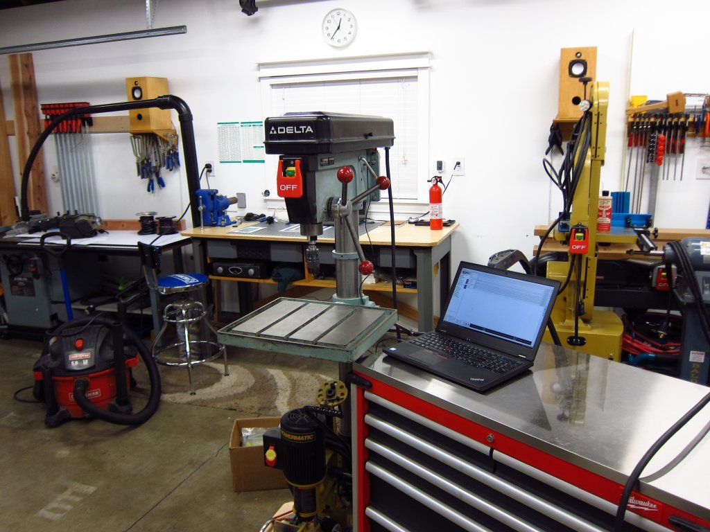
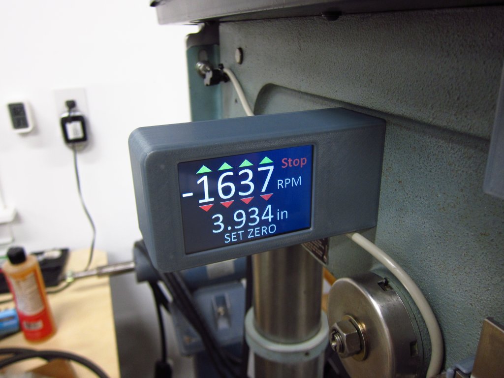
After much thinking and planning, here's how the controls and stuff settled. I ended up using a touch interface rather than any sort of knob, and I added a depth readout on the quill lol. This is a pretty fancy old drill press now!
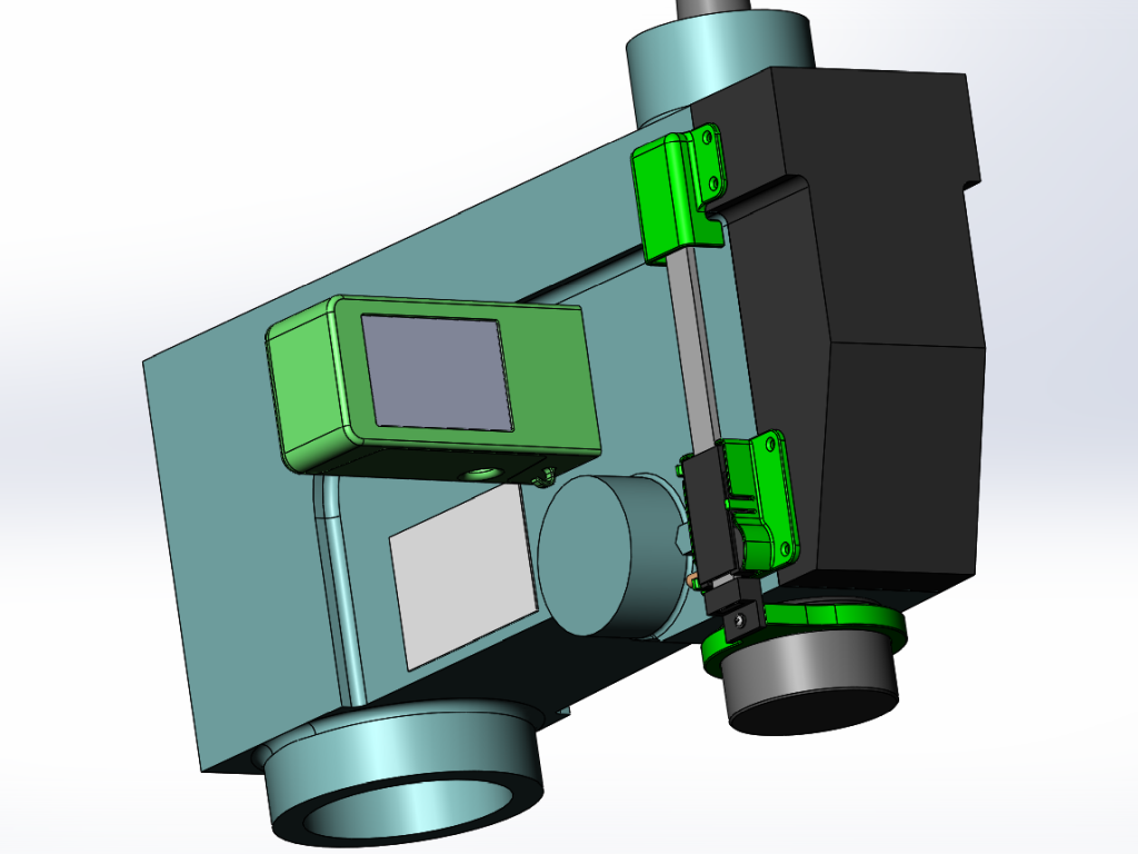
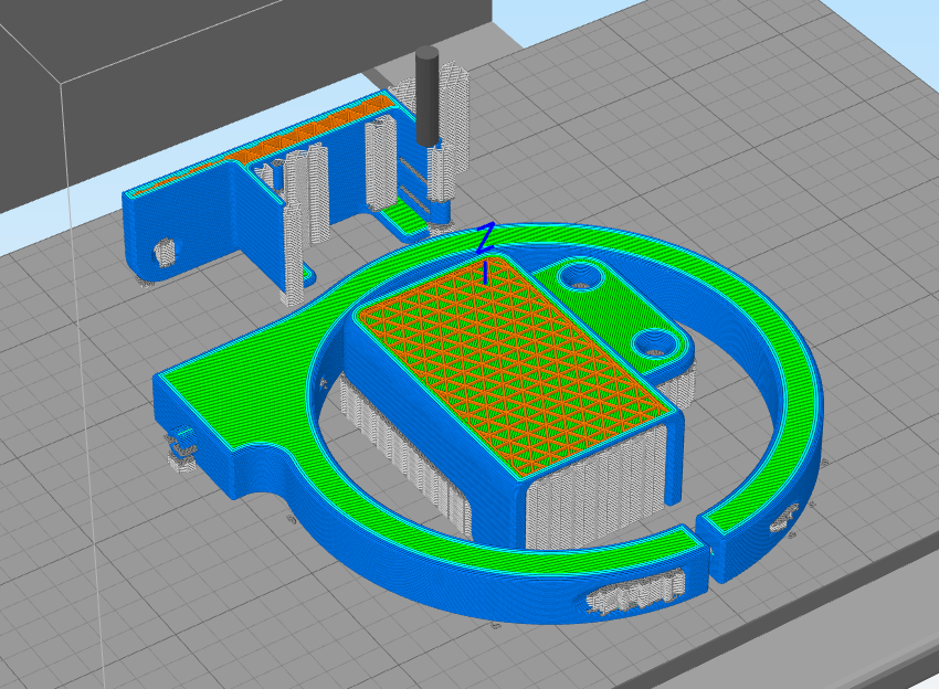
Lots of 3D printed stuff in there.
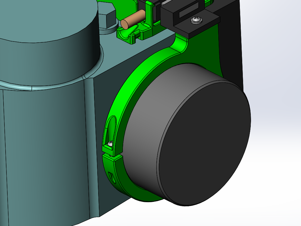
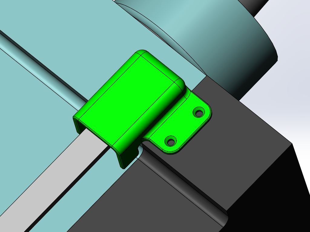
The depth readout used a cheap Amazon 6" / 150mm scale, and I just 3D printed the various parts I needed to adapt it. The collar on the quill just uses a tapping screw to draw it tight, the scale body clips into place with some spring fingers and other (not visible) features to keep it from moving up/down, and I added a little protector thing at the top to help keep stuff from getting caught on the top of the sliding rail.
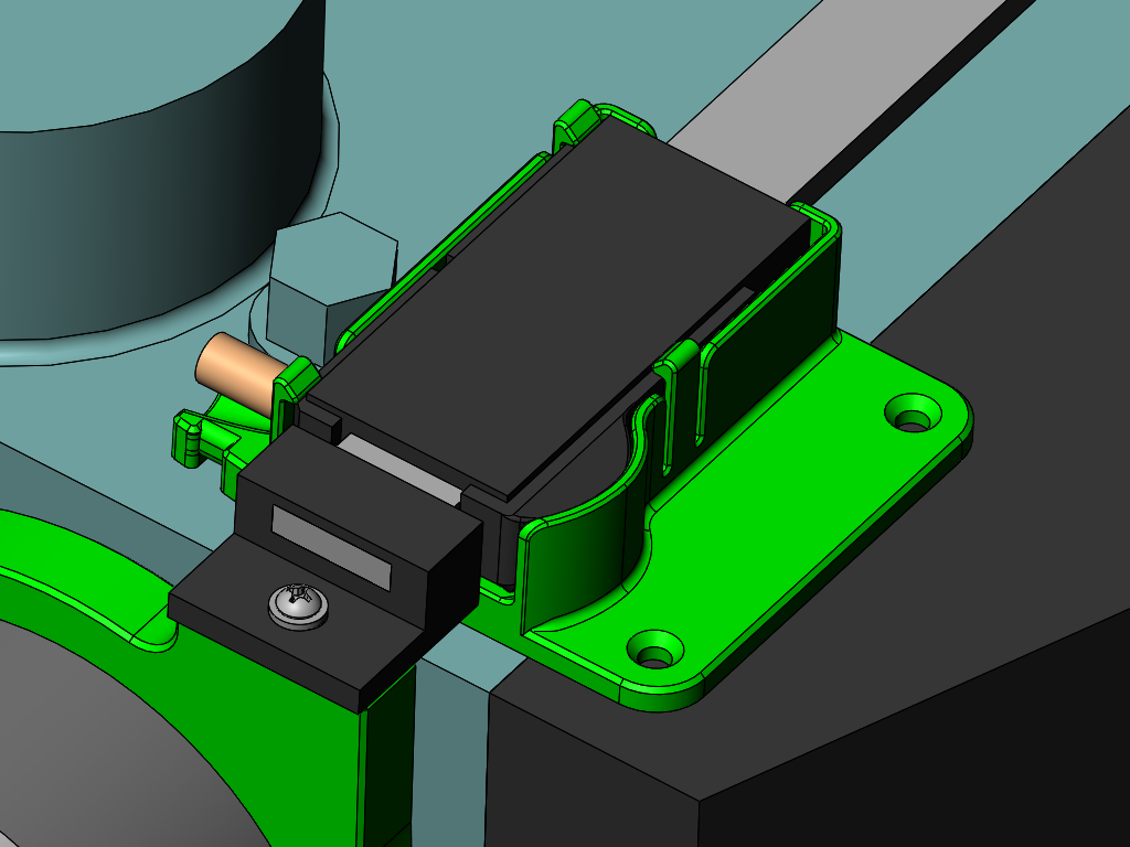
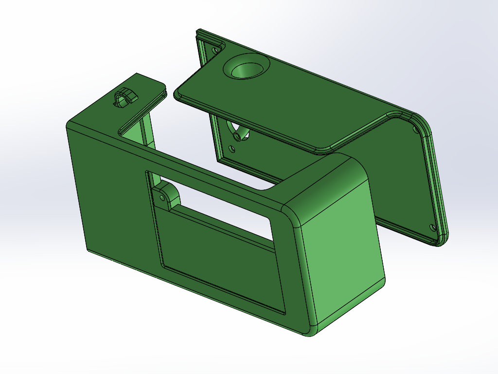
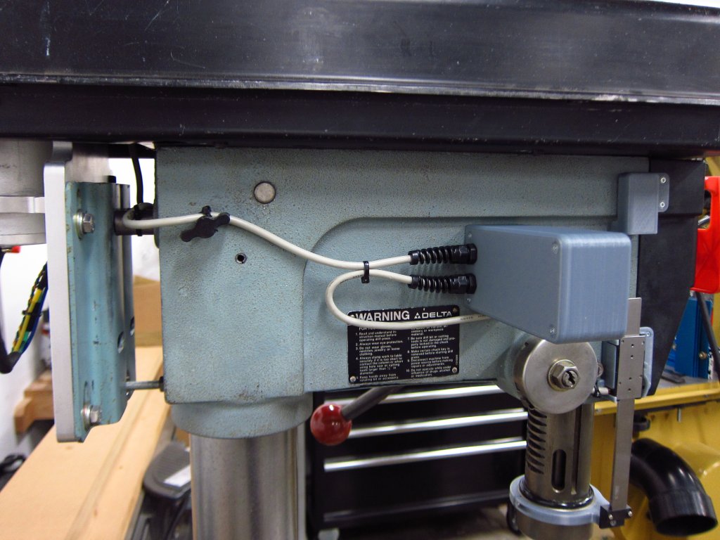
Similarly, the housing for the controls was 3D printed too. It is an interlocking clam shell with the big lower lip thing being there to allow me to get at the wire terminals and micro-SD card slot in the touch screen if I ever need to load a new interface onto it. The control board has a little piezo speaker on it to provide beeps as the touchscreen is used, and I designed in a little "horn" for it to help amplify the sound and get it out of the enclosure.
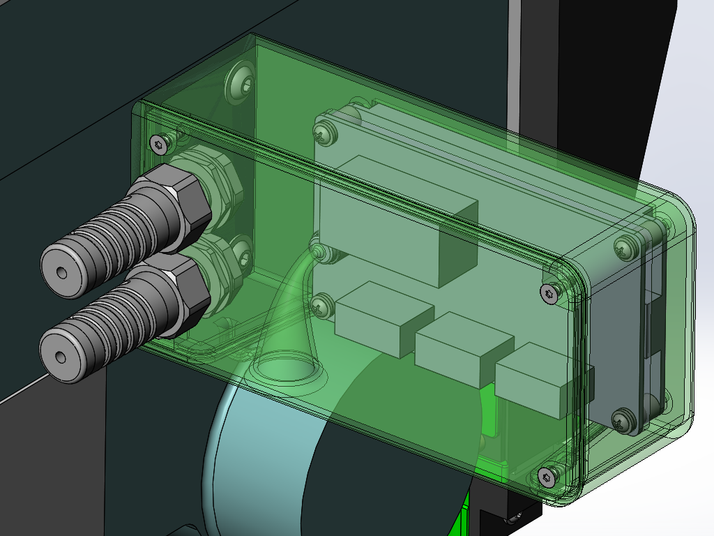
For the controls, I used a Teensy 3.2 as the MCU, and a Nextion 3.5" touchscreen to handle user input. Since PCBs are so cheap to have made these days, I designed a nice simple one to get everything in one place. The digital scale runs on 1.5V, and the Teensy uses 3.3V, so I needed some logic level shifting and a 1.5V power supply to power it (no batteries!). So the ESC provides 5V, the Teensy has its own 3.3V regulator which powers the 1.5V regulator on my board, which powers the scale (~16mA when on). The ground planes/pours are hidden so you can see the rest of the layout.
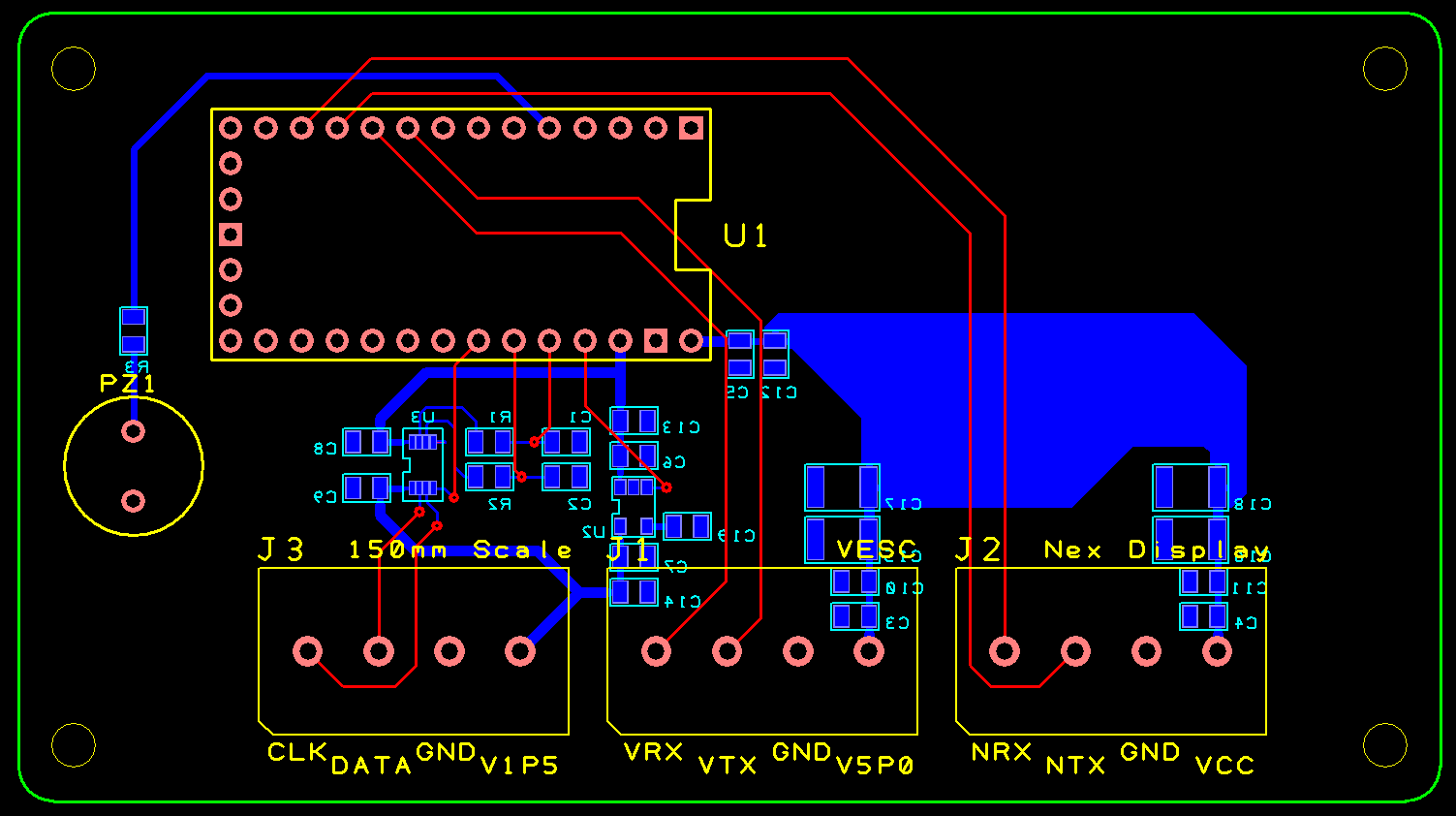
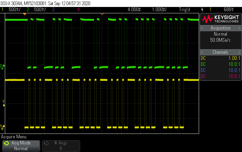
Basically every cheap Chinese digital scale / caliper has a 4 terminal interface which can be used to get position readouts. If looking at the caliper face normally, the pins are usually (left to right) GND, Data, CLK, Vin (1.5V). A number of places on the web have info on the protocol, but it is in most cases packets of 24 bits with the first 16-20 of them being the actual position, and then a few further up for the inch/mm setting and positive/negative reading. I verified what was what on a scope.
OK, so that's all well and good...pretty CAD pictures and whatnot, but what about actually doing it? Here it is!
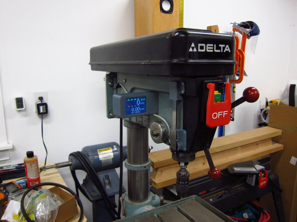
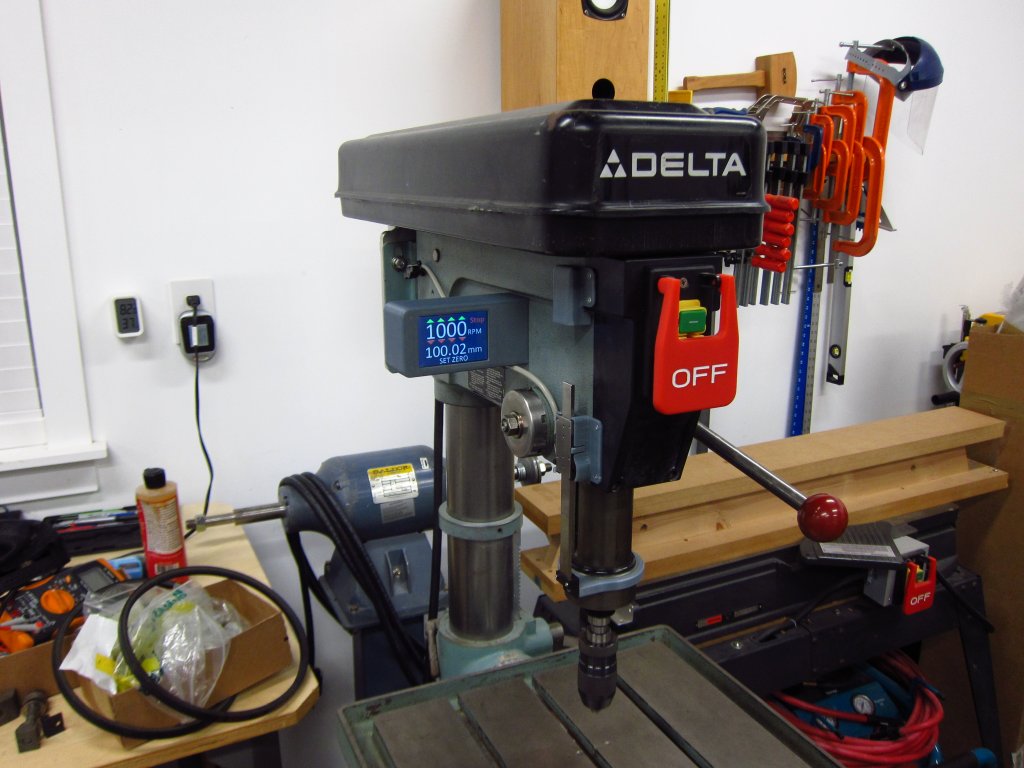
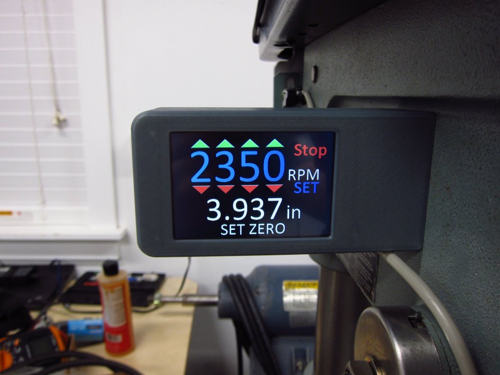
Features:
- Forward and reverse running
- Depth readout with zero-offset function
- Selectable inch / mm depth reading
- 150-5000RPM range, in 1 RPM increments
- PID speed control, so the ESC increases motor torque as the spindle gets loaded
I want to add a couple of things eventually:
- Optical pickup on the spindle pulley: right now the ESC reports the motor RPM via UART, and I programmed the controller to calculate spindle RPM based on pulley ratios. Reading the "real" spindle RPM would enable me to implement stall detection, which could save the V-belt if the spindle got stuck but the motor kept spinning.
- Belt tensioning pulley to reduce belt whip at certain RPMs
There it is folks. Overkill? Yeah. Awesome? Definitely.Leave a comment:
-
Holy shit, it has been almost a year since I last posted in here. Between COVID, blowing the HG in my 2.1L M42 and getting it rebuilt and "life stuff" I let this project fester for way too long. I am nearly done with the conversion, and it is pretty damn cool. Sadly, for the money I put into everything on this drill press, I could have bought a brand new Nova Voyager and had everything I wanted right out of the box. Then again, we all roll around in creaking 30 year old German steel boxes when many of us could have bought a newer "better" sports car for the same money, so I guess that this is the tool equivalent of what we do with E30's.
I have a load of pictures & CAD shots to put up here when I am done. At this point I am just finishing the design for the 3D printed enclosure for the controls / touchscreen. Yeah, my drill press has a touchscreen interface now lol. It's the future and shit. More to come...Leave a comment:
-
Super cool! Good job on getting it done...clearly I have over-complicated my setup lol.
I am mostly done with the custom machined parts and stuff, and just need to finish the shaft adapter bits to get the new pulley to be driven. In the last couple of months I picked up a 2006 Jetts TDI as a spare car for the impending E30 repaint, and of course it has turned into a new project vehicle despite telling myself it was not going to be a project vehicle! Anyway, I'll get some updates in here with my drill press project soon enough. God help me, I hope that the scooter motor I bought actually works for this!Leave a comment:
-
i finished this project up today.
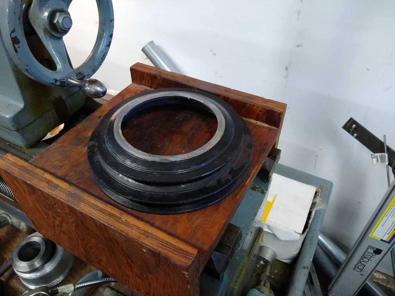
I used my lathe to make adapters for these pulleys. the one on the motor came from the water pump on an e36. the one in the foreground came off a junkyard mercedes.
a couple pics of the machining:
[IMG]https://imagizer.imageshack.com/v2/1280x1024q90/924/mbuSlA.jpg[/IMG]
[IMG]https://imagizer.imageshack.com/v2/1280x1024q90/923/jVu07b.jpg[/IMG]
[IMG]https://imagizer.imageshack.com/v2/1280x1024q90/922/fnrbGp.jpg[/IMG]
[IMG]https://imagizer.imageshack.com/v2/1280x1024q90/921/sOryiA.jpg[/IMG]
[IMG]https://imagizer.imageshack.com/v2/1280x1024q90/921/bcBP5w.jpg[/IMG]
here is a youtube vid:
im pretty happy in total. in practice, the high rpm is probably much faster than i'll ever need or use. eventually, ill probably switch to a smaller pulley on the motor. a little more motor rpm would give me more torque on the low end.Last edited by flyboyx; 10-17-2019, 12:23 PM.Leave a comment:
-
that is indeed a whole lotta awesome! good job. this will be amazing when you are done.
following OP's lead,i picked up some parts for my drill press too. not to jack your thread, but i wanted to post them and thought it would be redundant to make another thread.
i went with the traditional way we talked about above.
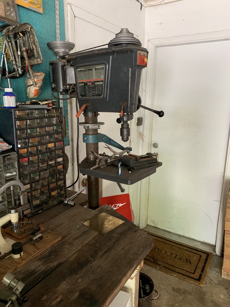
This is my mid 1960's, made in the usa, medium size floor model Craftsman press. it came to me with the pictured 1/2 hp induction motor.
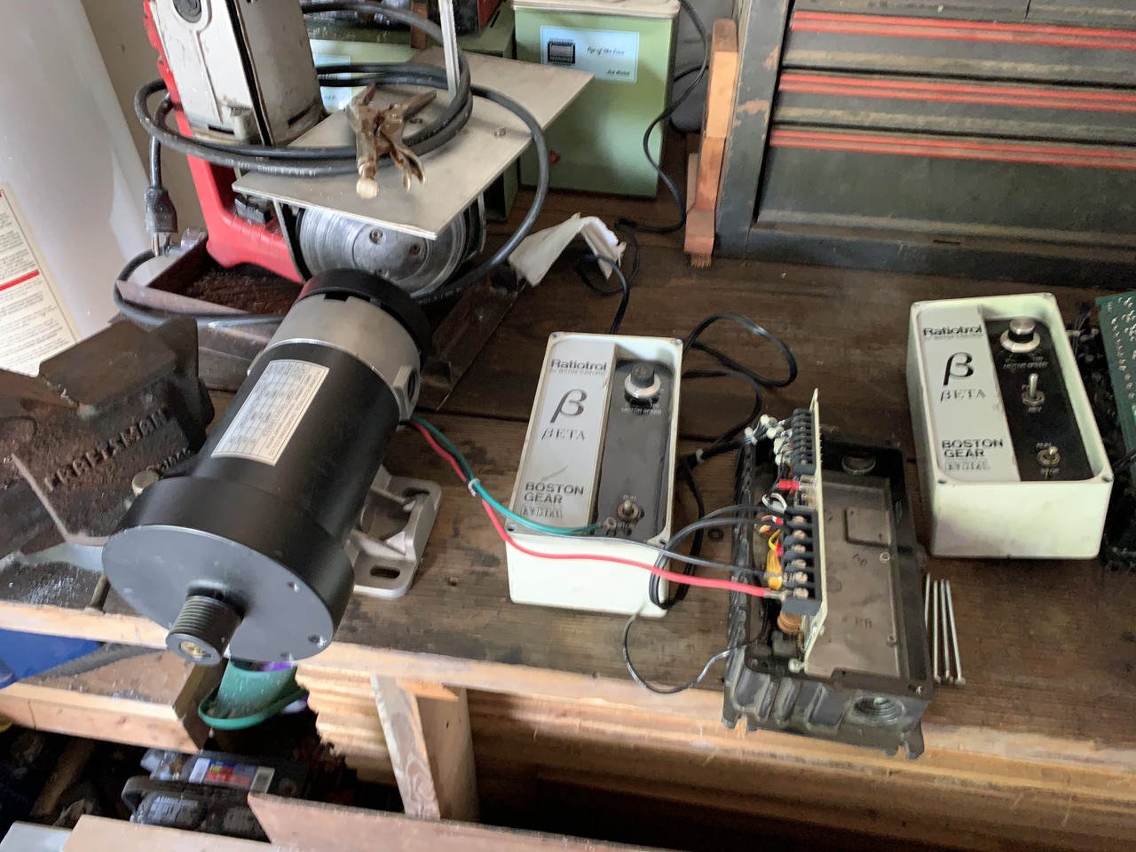
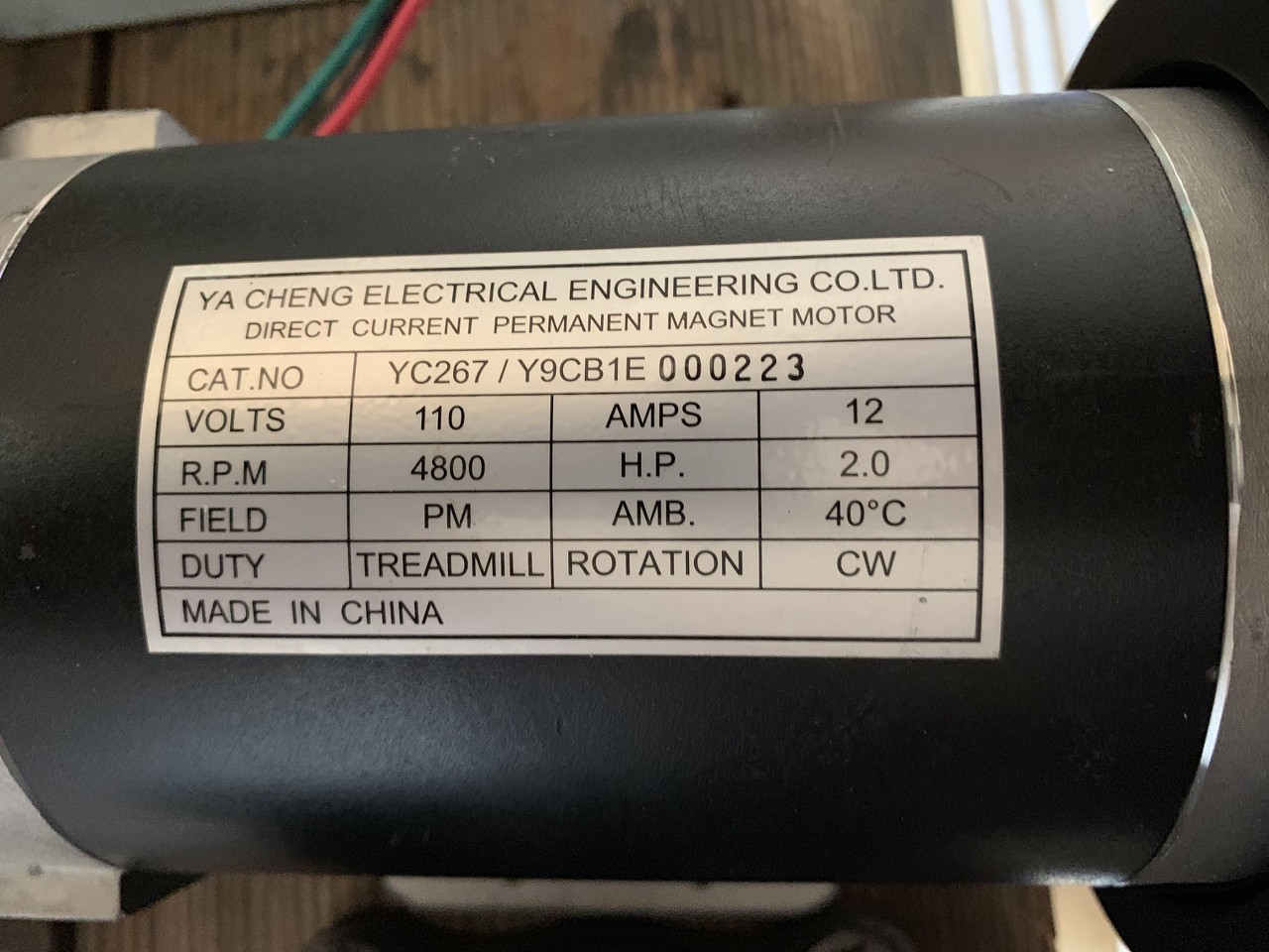
from ebay, i picked up this 2hp DC perm magnet motor for 65.00 shipped. it is brand new and never installed. it even has a cooling fan on the back end. i really like that it came with a nice mounting bracket that will fit perfectly against the original plate. 4800 rpm at 110 volts. the controller has a max output of 90 volts, so at full speed it should be running at about 4000 rpm. you will notice there are two Boston Gear ratiotrol boxes in the photo above. the one on the far right with reverse(that i don't care about) doesn't work. however, the middle terminal on all five diodes has been clipped off. i think perhaps if i replace them it may be fine. that one cost 35.00 shipped. the controller on the left, connected to the motor in the pic cost 52.00 shipped and it works great. I think that if i can get the non-working one fixed, i will try installing it on my table saw.
so, i have about 120.00 invested in my upgrade not including the controller that doesn't work. i still need pulleys and belt.. my setup has a 1" shaft on the headstock and 5/8" on the motor. i like the idea of using a serpentine belt, so i think i will get them off cars in the junk yard and machine the shaft hole to fit my needs. i would like a max speed of 8000 rpm, so i am thinking a 4" pulley on the motor and one half that size for the headstock. planning to modify the motor mount bracket on the drill so it is more steady as bmwman did in his project. i think it would be a good idea to take my headstock apart and clean it all up-possibly replace the bearings also.
here is a little youtube action vid i made.
i think the motor is pretty quiet. it is certainly good enough for my needs.
Last edited by flyboyx; 09-12-2019, 12:41 AM.Leave a comment:
-
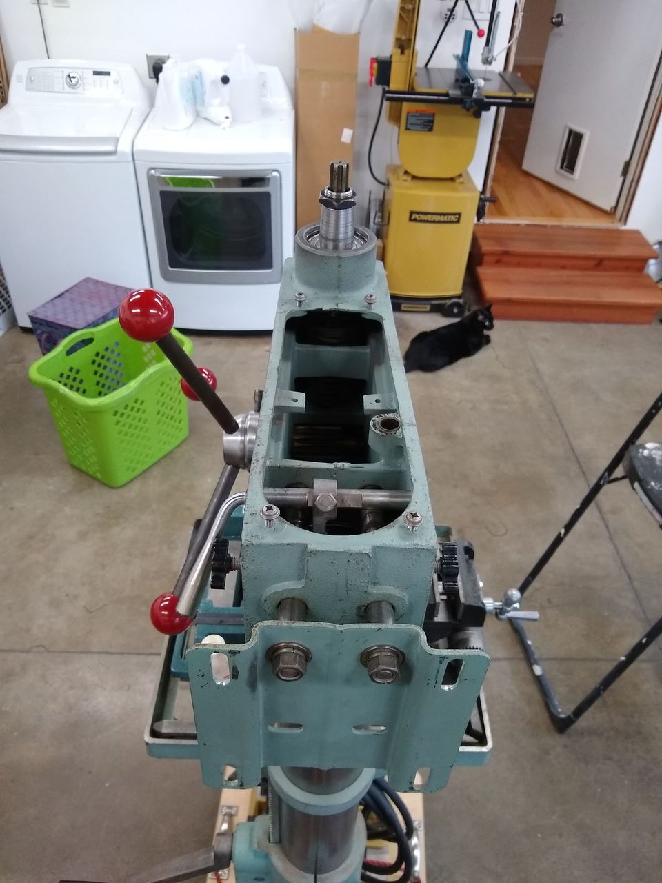
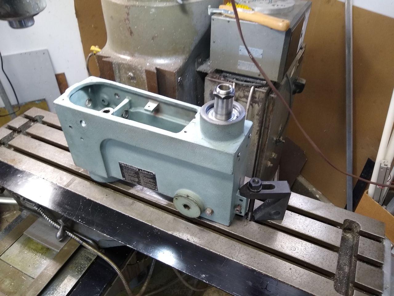
OK, the conversion is well under way now. Here's the deal.
First, I made some accurate-enough CAD models of the drill press head, pulleys, motor and PSU. After much noodling about where to put the PSU, I decided that it would be best to locate it inside the belt housing. It has some very high-flowing fans, which are loud and will suck sawdust, so the belt housing will help a little. Since this thing will not operate in any sort of continuous fashion, thermals are not much of a concern.
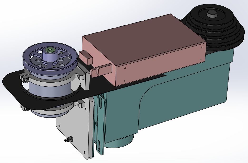
Things are a little tight, no? A number of modifications were needed to the drill press:
1) The step pulley on the spindle would need the 3 unused sections removed
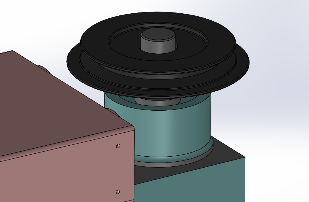
2) The top "deck" of the head casting would need to be lowered a few millimeters to give the PSU adequate clearance under the V-belt. With no changes, there is a ~3.5mm gap. I'd prefer to have a bit more room, like 7mm just to make sure no accidental contact occurs.
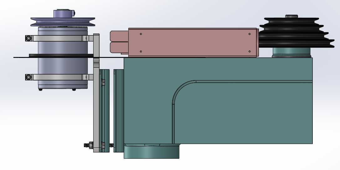
3) The motor mount bracket has always vibrated a lot since it is basically a big cantilever. To eliminate this, I will have a long M8 threaded rod and some nuts rigidly secure its bottom to the head casting. Since I am eliminating the step pulleys, this poses no inconvenience.
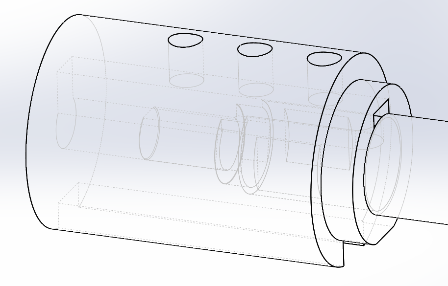
The new motor will be held by some machined aluminum collars, all mounted to an aluminum back plate.
Getting the new pulley onto the motor will take most of the work. The existing shaft will have some JB Weld fill in the flat sections (not structural, but will give a little more bearing surface), and then sections of it will be turned down a little to clean things up. It's machine pretty poorly from the factory. Also, the 6001 sealed bearings are cheap as hell and I am replacing them with some nice SKF ones.
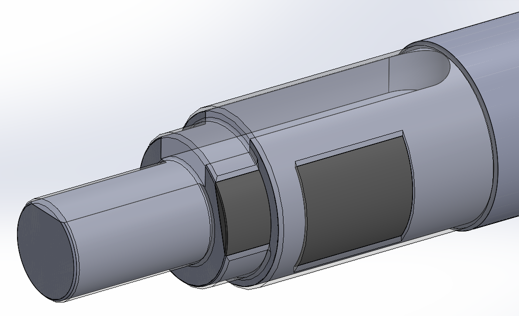
The adapter will be locked to the shaft with a 3/16" machine key, and then the pulley will use a 1/4" key. McMaster sells shaft stock with external keyways already machined into them, so I only need to turn the inner features, part it and broach the 3/16" keyway.
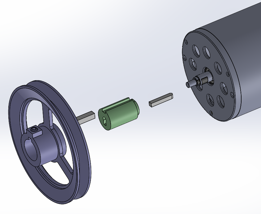
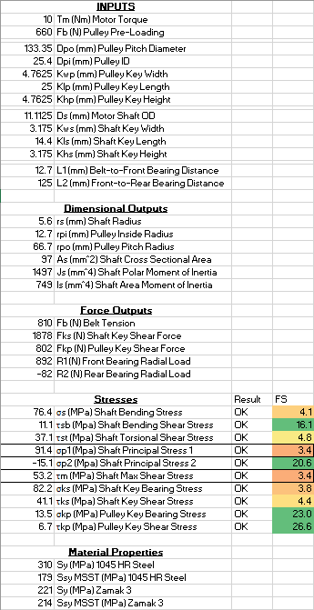
I had my concerns about the bending stresses that would be generated with this setup since the V-belt is pretty far off from the front bearing, and the shaft is not very large. Using some very conservative worst-case assumptions, I found that I still had a safety factor of >3, so the shaft should hold up just fine.
So, lots of CAD and Excel stuff. Cool story bro?
Nah, after getting the general design idea settled, it was time to start doing stuff.
The step pulley was parted down. Not only did it give my PSU the horizontal clearance I wanted, but it also SIGNIFICANTLY reduces the rotating mass of the system. There are pros and cons to this. The con, potentially, is that I could get a little more motor-borne vibration at higher spindle speeds. The pros are faster start/stop and (likely) less vibration since the thing was not perfectly balanced to begin with, it now weighs a lot less and it has a vastly smaller polar moment of inertia for any unbalance to leverage.
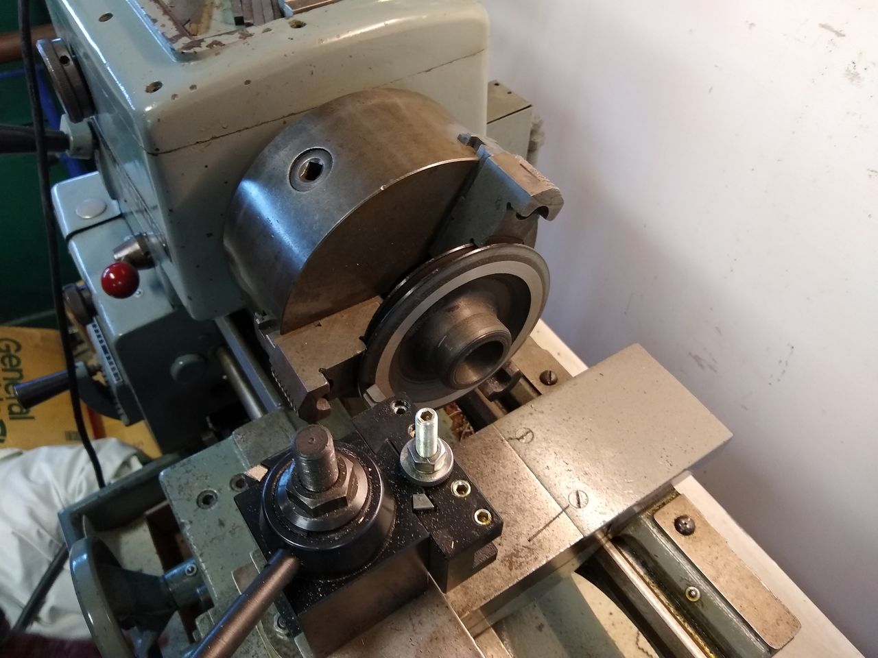
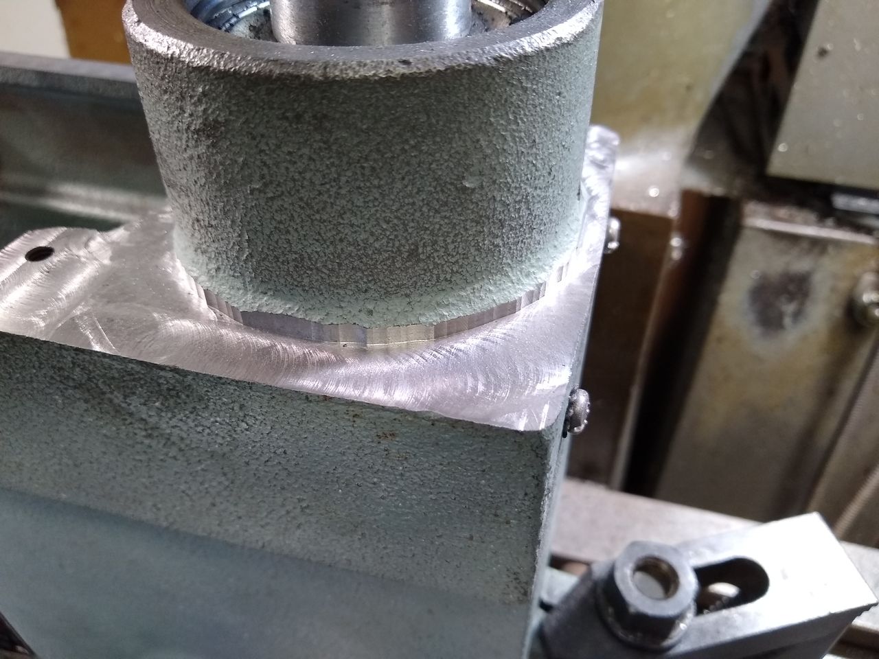
Machining the deck down was pretty simple, too. The bottom of the head has two machined co-planar surfaces, so it was just a matter of getting it on the bed and clamping it. A 3/4" end mill cleaned it up nicely.
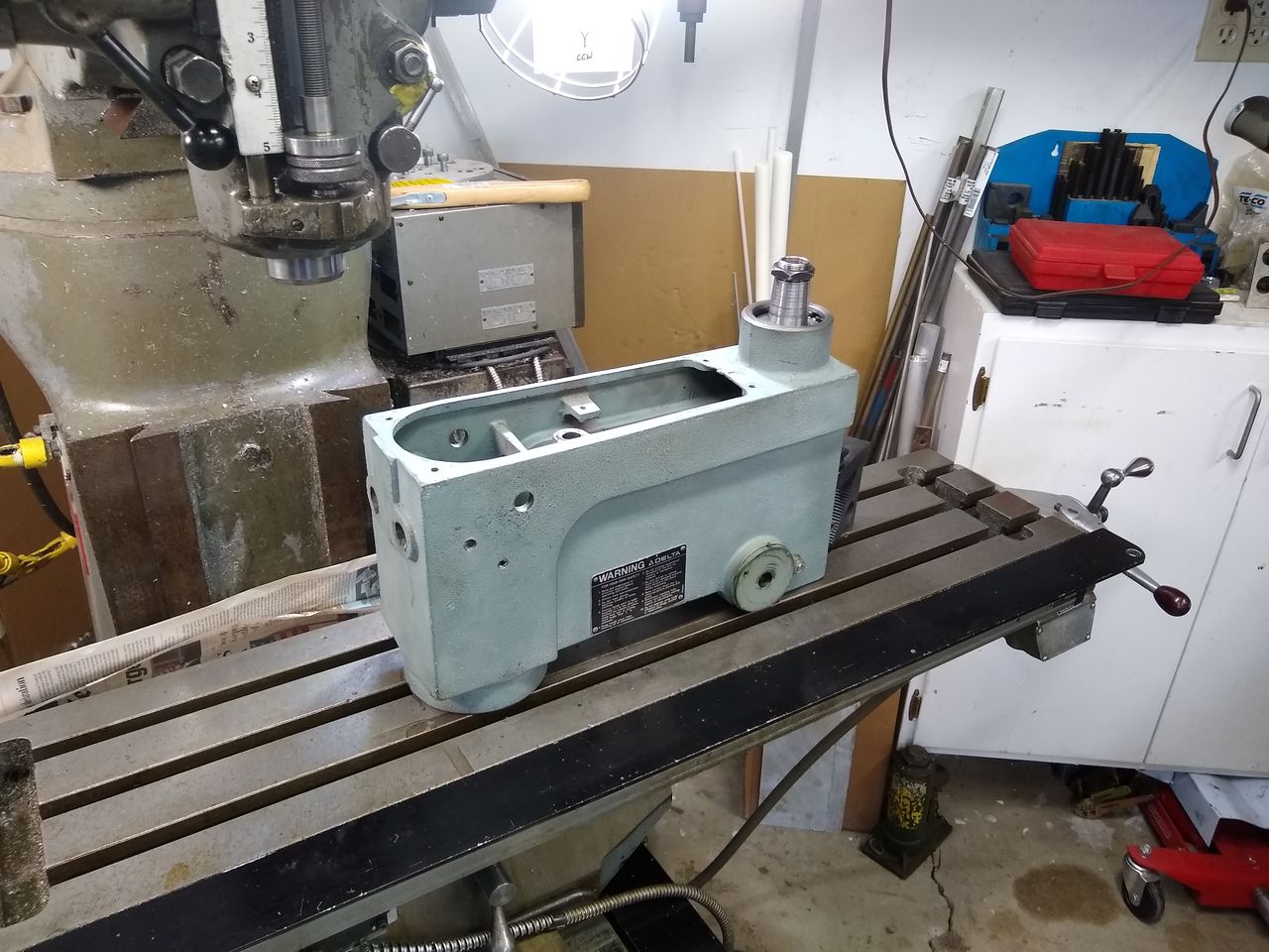
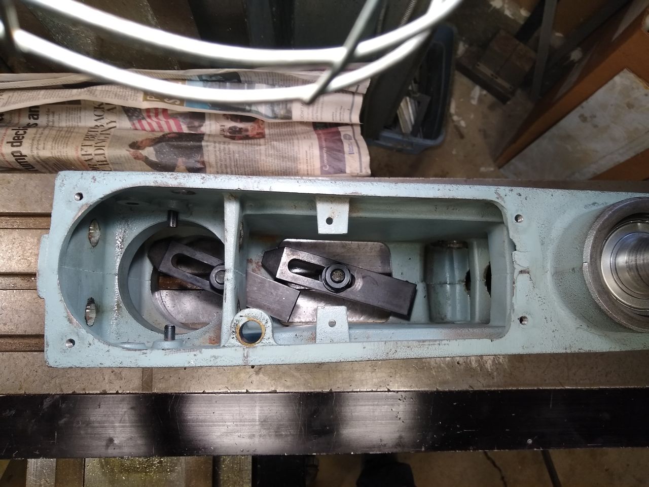
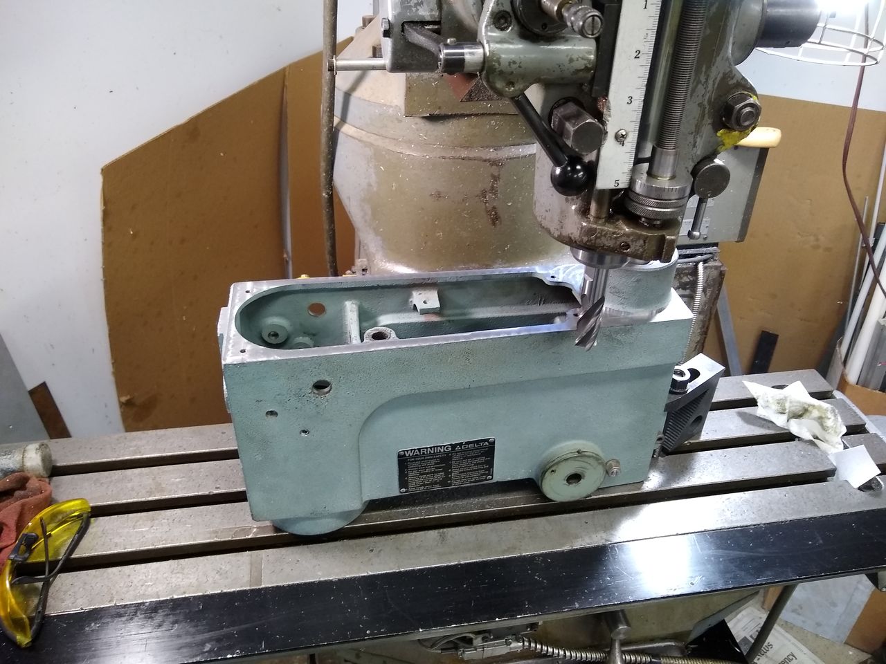
Since the mill is manual, I nibbled things close to the spindle bearing boss. Final cleanup can be done with a file. It needed to be somewhat close to clear the opening in the belt housing.
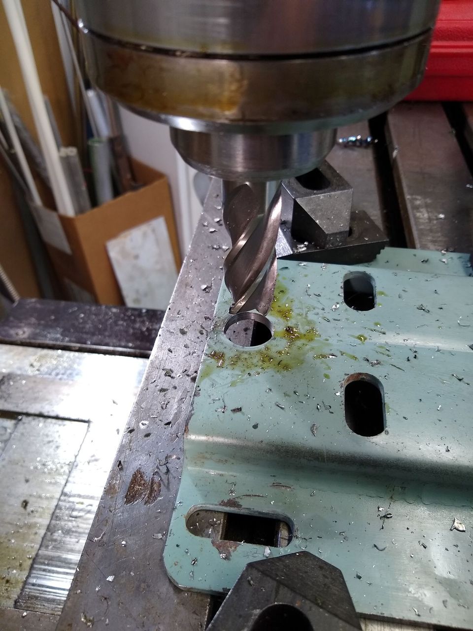
Finally for the day, I made the required hole in the motor mount bracket. This allows finger access to the nut (lol?) which will lock the bottom of the assembly to the head to eliminate wobbling.
So that is it for now. I will need to cut the belt housing a bit to clear the motor adapter plate, and do all the stuff with the new motor shaft & adapter. That is probably next weekend's project, or maybe this week after work if I can find the time.Leave a comment:
-
OK, so does anyone on here want to buy the DC motor control and 2 working DC motors from me?
- The first one which I got on eBay had a worn bearing, so I am replacing both of them. The new bearings are high quality NTN double-sealed ones from Motion Industries, which I should have in a week or so.
- I then bought a second one (see Surplus Center link) which is "new". I disassembled it to get some measurements on it (too large a diameter for even my 12" caliper jaws) and found that one of the internal permanent magnets was cracked. I pulled out the small loose piece, and there are some larger bits which appear to still be glued into place. Once I got the chipped bits out and reassembled, it runs fine and does not make crunching noises or anything...seems to be fine.

- The motor control is brand new and in immaculate condition. Apparently this model does not have a braking module accessory option. That alone wouldn't be a deal breaker on the whole project, but the motors I bought irk me.
Anyway, both of the DC motors are about as loud as the AC induction motor on the press now, and my OCD is triggered by these surplus goods lol. I'll sell all 3 items for $200 shipped (everything, including nice new ball bearings, were $330 with shipping when I got them). Let me know if you are interested before I plop it all on Craigslist.
So, WAT DO NOW? BLDC motor conversion, that is what. Yes, I have just wasted a really good bottle of Scotch's worth of money figuring out how I don't want to do this. Also, yes, the BLDC parts are another chunk of mostly-unnecessary change. Compared to what I, and many of us here, have done with our 30 year old cars, I feel no guilt. YOLOLeave a comment:
-
Yeah $155 shipped seemed pretty good for new commercial-grade DC motor drive box. Agreed, it is too bad that none of them come with the brake accessory, but I will keep an eye out for a deal on one. Chances are that once I put in pulleys with a LOT less mass, the spindle will come to a stop much more quickly. The stock main spindle pulley has to be north of 5lbs, and close to 10" in diameter at its largest. It probably helps to smooth the operation a little, similar to a flywheel in a car.
We'll see how it does. It is an SCR-type drive, so there is the inherent RFI that will be generated, and the motor will be a bit noisier with the 120Hz fundamental harmonic from the chopping action. I am still hopeful that it will run quieter than the TEFC induction motor that is on there now.Leave a comment:
-
That’s really cool man. So that controller was around 200 bucks? Not cheap, but I think it will serve you well. I found my lathe controller on eBay too. Apparently the guy selling it found it at an estate sale. I bought it used, but it had never been installed before. The specs say it’s made for 1/8 to 1 hp. Apparently 45.00 shipped was a pretty good deal.
I am thinking about a way to make it modular so I can run my 1960’s craftsman press with it too. I guess I won’t find another that cheap.
I see there is a spot on the panel for brake. It’s a shame you don’t have that feature in your price point.Leave a comment:
-
OK, attempt #2 to do this with a treadmill motor on the cheap'ish. Back when I researched this a bunch a year or so ago, I found that KB / Nidec make decent DC motor drives which are reasonably priced on eBay. My inclination was to go with a KBPW-240D which is one of their PWM drives, but it has some power limitations with 90-130VDC motors and a couple of other missing features. So I went with the KBPC-225D SCR drive which has speed- and torque-control drive modes and can handle a lot more output current. All in all, this ran me $5 more than the first all-treadmill-parts eBay item which fell through, and in this case I have basically everything I need to run this out of the box. I can even maintain my 240V input too and just set the drive's MAX trimpot to not go much over 130VDC. As far as I can tell, it does NOT include dynamic braking functionality, which is something like $100 worth of accessory add-ons. I may just come up with a mechanical brake system since I will be machining custom pulleys and motor adapter brackets.
Other than that, I am still planning on making a microcontroller-based tach with some big 7-segment LED blocks.

https://www.ebay.com/itm/KB-ELECTRON...X/233290854397
https://www.ebay.com/itm/Used-Perman...d/173955411743Leave a comment:
-
You are correct that this is mostly a "cool factor" project, and I am 100% unconcerned about future resale value or recouping costs. I am already more than the original cost/value of this thing into it from the rebuild and keyless chuck. I still have the keyed chuck for it for the times when I am dealing with high torque operations like large hole saws and drilling steel plate, but the keyless is just fine and super fast for the other 90% of the stuff I do on it.
Braking functionality is mostly for frequent start-stop operations when I need to reposition a workpiece (or swap them) many times and don't want to do it with a 2" Forstner bit rotating near my fingers. I also often am in a situation where I need to do multiple holes in a part, starting with a pilot hole, then the actual hole and then countersink and/or tap it. To maintain concentricity, it is best done one hole at a time, swapping bits, and waiting for the spindle to stop on its own takes forever.
Yup! They are not actually DC motors in any similar sense as a brushed motor, except that the main power supply is DC. The controllers modulate the DC voltage into 3 phase trapezoidal or sinusoidal signals. The motor's stator windings interact with permanent magnets on the rotor to spin it.
I am just guessing on the year based on the manuals for it I found online. I do sort of like some of the older woodworking tools more than the newer ones since they seem to have a lot more cast iron in them.Leave a comment:
-
Nice job!
I inherited a Delta 17-900 of about the same vintage from my woodworking neighbor. How did you find out what year it was made? I see yours is also Taiwanese.
I like the old vintage machinery, also have 1987 Ohio Forge 510-440 table top DP, 1955 Delta Toolmaker, a 70's Sioux Valve grinding station, 1983 Miller Syncrowave etc...Leave a comment:


Leave a comment: