
Hello all,
Here I'll be documenting the installation of a new aftermarket alarm for my E30. In my case, I went with the Scytek Galaxy G20 after reading countless reviews and recommendations. There are many tips and short writeups on the E30 alarm installation, but I haven't found them all in one place. I will attempt to do that here. This post will be continually edited as I go through the process.
My '84 318i is parked right now while I wait for new calipers and rotors, so I thought this would be a good time to document this project correctly.
Goal -- Properly wired reliable alarm installation with many features enabled, including:
Lock/Unlock
Door(s) sensor
Trunk sensor
Dual-stage shock sensor
Siren
Valet Switch
Mount LED with OEM look
Dome light supervision on unlock
All parking lights flash with lock/unlock
Remote trunk release
And as a bonus I plan to add:
Radio and window switches remain active until door is opened
Supply List:
Scytek Galaxy G20 (~$35, internet)
4 Automotive relays (+3 for Accessory-until-door-open feature) ($5-7, electronics supply such as Radio Shack)
1 1A 50V rectifier diodes ($1/ea, electronics supply) (+2 more for retained accessory power)
2 6A 50V rectifier diodes ($1.50/ea, electronics supply)
DEI 524N 2-wire door lock motor kit (~$15, internet)
Wire Stripper, Crimper, Quick Disconnect Terminals (for relays), Pack of butt connectors, lots of wire (auto parts store or electronic supply if you don't already own these things)
Link Collection for the guide:
R3vlimited Links:
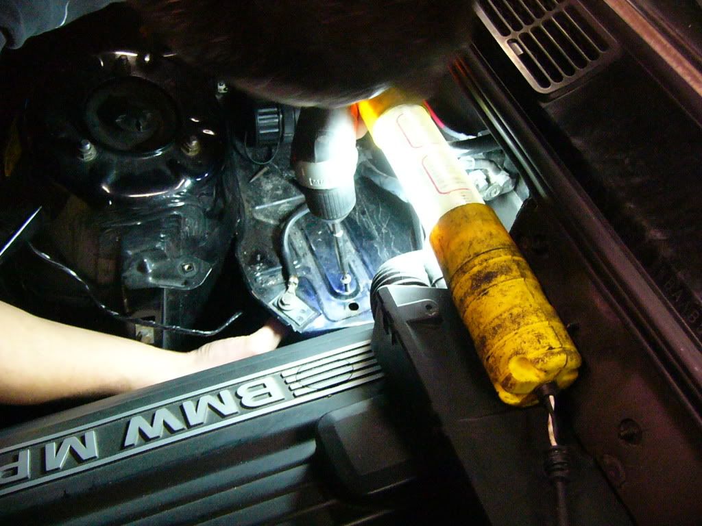
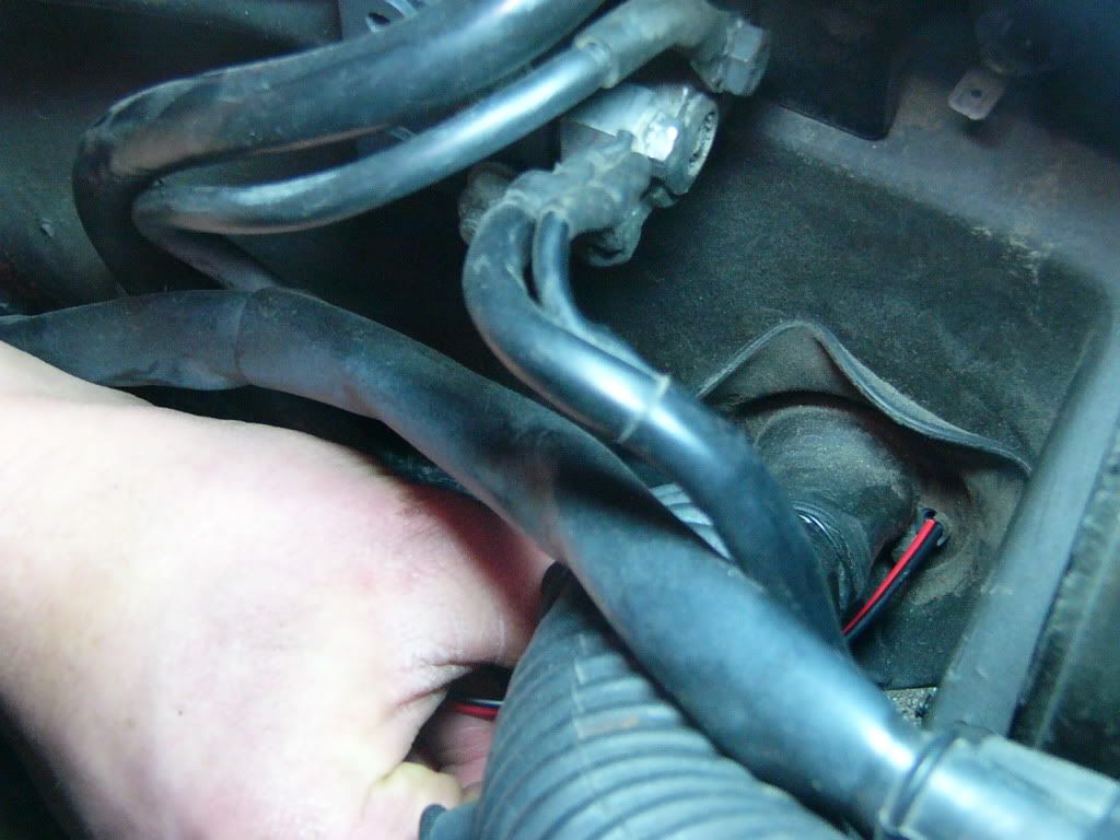
Mount the siren under the battery tray and feed the wire through the firewall
Installing the starter kill is not recommended
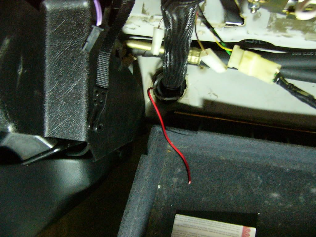
Green wire (door sensor) on Scytek goes to brown/purple in kickpanel
G20 needs relays for lock/unlock or it will self-destruct (most alarms can't handle the 1.2A needed to trigger the door actuators)
Some E30s have 'delayed entry module' relay that can be used to activate the dome lights (mine does not have this feature)
How to wire the horn with a relay
How to wire the door lock/unlock relays
How to wire the dome light relay
Aux fuse box
12Volt.com Links
Wiring detail for my 1984 318i
Isolate the trunk pin with a diode for use as the trunk sensor
Retained accessory power
Wiring the 2 parking light circuits with relays (More costly than the diode method)
Other links:
E30 wiring schematics
Crutchfield alarm installation tips
Shock sensor mounting tips
German alarm suggestions
Wiring both parking light circuits to flash by using diodes
Example installations of the DEI 524N trunk release
Wiring a new fuse into the aux fuse box [PDF]
Hood pin installation suggestion
More about the delayed entry module and how to retrofit
Electronics parts stores in the Seattle area
Wiring diagram from the Scytek G20 manual

My Scytek to E30 Wiring diagram
This diagram drawn with QUCS free circuit diagram softwares (Windows download here).
Sixth edition of the alarm wiring diagram. This edition has 1A and 6A diodes.
(This diagram is without the retained accessory power.)

Forgot to take a photo of the new G20 before I prewired it, so here's the complete package with prewiring:
In this photo you can see the valet switch and LED with wiring coiled on the left. Siren is on the right.
One of the reasons I chose the G20 is that the remotes look clean and modern - most inexpensive alarms have hideous remotes, and the remote is the only part of the alarm everyone will see. Although I wanted a deal on an alarm I didn't want it to look, feel, or perform cheaply. The remotes are shiny and look durable, and the LED is bright.

And here are the prewiring photos:
1. Wiring 6A50V rectifier diode for one of the parking light circuits
Diodes are one-way valves for electricity, electricity only flows toward the direction of the silver band. I trimmed down the diode leads and used butt connectors because they are less prone to damage from vibration than if I had soldered. Also it was easier and I have a ton of connectors. Don't forget, before you tape mark the tip of the butt connector that is on the same side as the silver band so you know in which direction to wire it!
2. Both sets of parking light diodes
The 6A50V rating means that each diode can handle 6 Amps of current, and that it will take at least 50 Volts of electricity in the wrong direction before the valve will be overcome. Each of the parking light circuits is ~5A (if you look at the Scytek's parking light wire it has a 10A fuse for all the lights).

3. Parking light diodes wired in parallel
You can see my black marks on the end of the butt connectors in this photo. The current will be going from left to right. I used 16 gauge wire throughout this project, which is sufficient for up to a 15A load.

4. Parking light diodes connected to the Scytek wiring

5. Parking light wiring safely wrapped up

6. Testing continuity of the parking light circuit with the multimeter (Ohms)
Testing the high resistance of the diodes in the 20,000 Ohm range.

7. Testing continuity of the parking light circuit with the multimeter (Diode)
Testing the high resistance of the diodes using the multimeter's diode test function. I did check each set of diodes although that is not shown.

8. Wiring the relays to ground
Each of the relays terminal 30 wired in parallel to ground

9. Wiring the relays to 12V
Each of the relays terminal 85 wired in parallel to 12V.
Also shown (from left to right) are the dome light supervision, lock, and unlock wires from the Scytek.

10. Wiring the relays to the Scytek
The dome light supervision, unlock, and lock wires from the Scytek connected to the relay terminals 86.

11. Wiring the Scytek door trigger to same circuit as the dome light supervision relay
The green door trigger wire is on the same circuit as terminal 87 of the dome light relay.

12. Relays shown from top

13. Terminals 87 from the relays
Terminals 87 labeled for connection with the 318's wiring circuits.

14. Tape off unused wires
We won't be using the orange (starter kill), brown (horn trigger) or purple (door trigger positive) for this install, so cut and tape them off and coil them neatly.

15. Wiring one 3A50V rectifier diode for the trunk trigger
The trunk switch also activates the trunk light, so the circuit must be isolated with at least a 1A12V diode. Again I put the black mark on the butt connector to show the direction of the diode before taping.

16. Testing the continuity of the trunk trigger circuit
The blue trunk trigger wire from the Scytek, connected to the diode, tested with the multimeter's diode test function.

17. The Scytek Galaxy G20 shown prewired as in the circuit diagram.

Continue on to the install photos on post #38...
More edits to come...
Here I'll be documenting the installation of a new aftermarket alarm for my E30. In my case, I went with the Scytek Galaxy G20 after reading countless reviews and recommendations. There are many tips and short writeups on the E30 alarm installation, but I haven't found them all in one place. I will attempt to do that here. This post will be continually edited as I go through the process.
My '84 318i is parked right now while I wait for new calipers and rotors, so I thought this would be a good time to document this project correctly.
Goal -- Properly wired reliable alarm installation with many features enabled, including:
Lock/Unlock
Door(s) sensor
Trunk sensor
Dual-stage shock sensor
Siren
Valet Switch
Mount LED with OEM look
Dome light supervision on unlock
All parking lights flash with lock/unlock
Remote trunk release
And as a bonus I plan to add:
Radio and window switches remain active until door is opened
Supply List:
Scytek Galaxy G20 (~$35, internet)
4 Automotive relays (+3 for Accessory-until-door-open feature) ($5-7, electronics supply such as Radio Shack)
1 1A 50V rectifier diodes ($1/ea, electronics supply) (+2 more for retained accessory power)
2 6A 50V rectifier diodes ($1.50/ea, electronics supply)
DEI 524N 2-wire door lock motor kit (~$15, internet)
Wire Stripper, Crimper, Quick Disconnect Terminals (for relays), Pack of butt connectors, lots of wire (auto parts store or electronic supply if you don't already own these things)
Link Collection for the guide:
R3vlimited Links:
Mount the siren under the battery tray and feed the wire through the firewall
Installing the starter kill is not recommended
Green wire (door sensor) on Scytek goes to brown/purple in kickpanel
G20 needs relays for lock/unlock or it will self-destruct (most alarms can't handle the 1.2A needed to trigger the door actuators)
Some E30s have 'delayed entry module' relay that can be used to activate the dome lights (mine does not have this feature)
How to wire the horn with a relay
How to wire the door lock/unlock relays
How to wire the dome light relay
Aux fuse box
12Volt.com Links
Wiring detail for my 1984 318i
Isolate the trunk pin with a diode for use as the trunk sensor
Retained accessory power
Wiring the 2 parking light circuits with relays (More costly than the diode method)
Other links:
E30 wiring schematics
Crutchfield alarm installation tips
Shock sensor mounting tips
German alarm suggestions
Wiring both parking light circuits to flash by using diodes
Example installations of the DEI 524N trunk release
Wiring a new fuse into the aux fuse box [PDF]
Hood pin installation suggestion
More about the delayed entry module and how to retrofit
Electronics parts stores in the Seattle area
Wiring diagram from the Scytek G20 manual
My Scytek to E30 Wiring diagram
This diagram drawn with QUCS free circuit diagram softwares (Windows download here).
Sixth edition of the alarm wiring diagram. This edition has 1A and 6A diodes.
(This diagram is without the retained accessory power.)
Forgot to take a photo of the new G20 before I prewired it, so here's the complete package with prewiring:
In this photo you can see the valet switch and LED with wiring coiled on the left. Siren is on the right.
One of the reasons I chose the G20 is that the remotes look clean and modern - most inexpensive alarms have hideous remotes, and the remote is the only part of the alarm everyone will see. Although I wanted a deal on an alarm I didn't want it to look, feel, or perform cheaply. The remotes are shiny and look durable, and the LED is bright.
And here are the prewiring photos:
1. Wiring 6A50V rectifier diode for one of the parking light circuits
Diodes are one-way valves for electricity, electricity only flows toward the direction of the silver band. I trimmed down the diode leads and used butt connectors because they are less prone to damage from vibration than if I had soldered. Also it was easier and I have a ton of connectors. Don't forget, before you tape mark the tip of the butt connector that is on the same side as the silver band so you know in which direction to wire it!
2. Both sets of parking light diodes
The 6A50V rating means that each diode can handle 6 Amps of current, and that it will take at least 50 Volts of electricity in the wrong direction before the valve will be overcome. Each of the parking light circuits is ~5A (if you look at the Scytek's parking light wire it has a 10A fuse for all the lights).
3. Parking light diodes wired in parallel
You can see my black marks on the end of the butt connectors in this photo. The current will be going from left to right. I used 16 gauge wire throughout this project, which is sufficient for up to a 15A load.
4. Parking light diodes connected to the Scytek wiring
5. Parking light wiring safely wrapped up
6. Testing continuity of the parking light circuit with the multimeter (Ohms)
Testing the high resistance of the diodes in the 20,000 Ohm range.
7. Testing continuity of the parking light circuit with the multimeter (Diode)
Testing the high resistance of the diodes using the multimeter's diode test function. I did check each set of diodes although that is not shown.
8. Wiring the relays to ground
Each of the relays terminal 30 wired in parallel to ground
9. Wiring the relays to 12V
Each of the relays terminal 85 wired in parallel to 12V.
Also shown (from left to right) are the dome light supervision, lock, and unlock wires from the Scytek.
10. Wiring the relays to the Scytek
The dome light supervision, unlock, and lock wires from the Scytek connected to the relay terminals 86.
11. Wiring the Scytek door trigger to same circuit as the dome light supervision relay
The green door trigger wire is on the same circuit as terminal 87 of the dome light relay.
12. Relays shown from top
13. Terminals 87 from the relays
Terminals 87 labeled for connection with the 318's wiring circuits.
14. Tape off unused wires
We won't be using the orange (starter kill), brown (horn trigger) or purple (door trigger positive) for this install, so cut and tape them off and coil them neatly.
15. Wiring one 3A50V rectifier diode for the trunk trigger
The trunk switch also activates the trunk light, so the circuit must be isolated with at least a 1A12V diode. Again I put the black mark on the butt connector to show the direction of the diode before taping.
16. Testing the continuity of the trunk trigger circuit
The blue trunk trigger wire from the Scytek, connected to the diode, tested with the multimeter's diode test function.
17. The Scytek Galaxy G20 shown prewired as in the circuit diagram.
Continue on to the install photos on post #38...
More edits to come...


Comment