If this is your first visit, be sure to
check out the FAQ by clicking the
link above. You may have to register
before you can post: click the register link above to proceed. To start viewing messages,
select the forum that you want to visit from the selection below.
Actually, since the faceplate isn't a complete nightmare to take apart, I can probably do the LEDs myself. The white backlighting on the main display is REALLY bright at night and it would be nice tone it down some - maybe the orange/amber will help with that.
Think a 15W soldering iron is enough for SMT stuff?
-Geno
'87 325is (s52'd)
'95 525iT
'02 Range Rover 4.6 HSE
'98 Disco 1
Two cheap-o 15W or 25W irons will be fine for reworking the 0805 and 0603 parts. Trust me, using 2 makes it way easier to remove them and almost eliminates the chances of ripping the copper pads off.
Cost...
Well, as far as the faceplate goes, I doubt I will offer that as a service. It would be on the order of $150 since it would be a fair amount of labor time, and I don't see too many people wanting to pay that much. I'll post detailed modding instructions on how to do it though.
As for the pre-amp board and whatnot, I am shooting for ~$125 for the PCB and hardware kit, and probably another $100-$150 if people want me to actually do the mods to install it. Again, there is a fair amount of labor involved. Install instructions will be documented for those that want to do it themselves.
So...not cheap, but that's sort of how it has to be since I will be hand-assembling the PCBs and wire harnesses. And I don't expect to make more than a dozen or so since there aren't too many people running the RMT200 in older BMWs.
"So...not cheap, but that's sort of how it has to be since I will be hand-assembling the PCBs and wire harnesses. And I don't expect to make more than a dozen or so since there aren't too many people running the RMT200 in older BMWs."
Hey guys, awesome stuff. I've bought 2 of these units to run in my E30s because they are super-functional while looking period-ish correct. I'm reading these posts with excitement cuz a few modifications would make the RMT200 really a great unit.
1993 Alpine White II 325i convertible (last year of E30 production)
1988 Zinnoberot 325 Super ETA coupe
Everyone starts somewhere. I knew squat about electronics and whatnot 8 years ago. Lots of reading, persistence and used textbooks got me on the right track! Granted, it helps if you don't mind spending some of your free time reading technical mumbo-jumbo!
Good question. For the most part, there is no reason at all why this board wouldn't work with basically any head unit. There are some differences in how different units produce 4-channel sound, and in some cases you might get better sound quality if the rear channels weren't used (you could still have 4 pre-amp outputs, but their source would be only the "front" signals), but I would assume that the C43 isn't one of those cases. Anyway, that's a bridge to cross when we get to it and it's probably not a big deal.
One other question...how important is it to folks to have 4 pre-amp outputs (FL/FR/RL/RR)? I assume that it is preferred in cases with multiple amps (one for sub and one for mids/tweets). Anyway, I ask because if people were happy with 2 (FL/FR) it would definitely allow the board to be even smaller, but it's no biggie either way.
As of now I am looking at setting the opamps up to provide 4V peak-peak outputs. Luke, you mentioned that 5V is good but might be a little bit of a pain with old-school amps. Based on your experience, would 4V play nice while still giving the a high enough signal level? I'm using a nice hi-fi grade Texas Instruments quad opamp so the signal coming out will be nice and clean in any case. Actually, to be clear, the outputs would be 4V before distortion/clipping and would max out at 4.8V when the signal is clipping badly (the DAC output can do 2.5V without distorting but above that it begins clipping with a max swing of 3V...my circuit would have a gain of 1.6 so 1.6 x 2.5V = 4V of clean signal).
One other question...how important is it to folks to have 4 pre-amp outputs (FL/FR/RL/RR)? I assume that it is preferred in cases with multiple amps (one for sub and one for mids/tweets). Anyway, I ask because if people were happy with 2 (FL/FR) it would definitely allow the board to be even smaller, but it's no biggie either way.
In my case, 2 channel would be fine. I've got my C43's front speaker inputs going into a JBL MS-8. But I would suspect that most people would prefer 4 channels so that they could have front-rear fading capability.
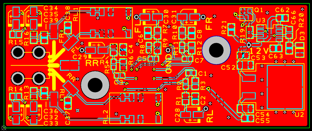
OK, prepare your butts E30 audio people. I have a first draft for the pre-out PCB done. It is designed to be screwed to the inside of the RMT200 on the right-side wall between the EMI cage and CD transport unit. Clearances are a little tight, but I sized the board and relays to have >1mm clearance all around. The relays were the real trick since they are relatively tall for the gap that everything has to fit in!
Anyway, I should have some PCB protos and components in a week or so. Next week I am on call for jury duty, so I may or may not get anything done here!
This thing is designed to be as good as or better quality than the PCB in the RMT200. Parts are AEC-Q200 certified (automotive grade) wherever possible, all SMD caps in the signal path are 1% tolerance C0G/NP0 grade, signal resistors are 0.5% tolerance THIN film, electrolytic coupling caps are rated for 105°C, and the audio filter opamp is a high quality TI audio-specialty unit. Oh and the outputs are protected by physical micro relays for prevention of silly pops/clicks and protection from ESD while plugging in the RCA's.
So, this thing is looking like it should give some good results!
Alighty, all components are on order and the PCB design is out for manufacturing. I actually re-designed the entire PCB and made some big improvements in layout that should also mean higher audio fidelity. Even though everything could have been routed pretty easily on 2 layers, I used a 4 layer board to provide maximum separation between the audio channels and to get some large copper planes in there to improve noise suppression.
I expect to have the components and PCBs in a week or so (depending on how the holidays affect shipping). Once I have one put together and installed in my RMT200, I'll have to do some listening tests. I also plan to add the ferrite jumper to the mainboard that will enable the switched 12V output pin on the main connector, which I will give plenty of details on here so others can do it. Orange LEDs are also on my list!
Luke, any chance I could send you the modded RMT200 in a few weeks and have you give it a whirl? You have waaaaaay more experience with car sound systems and you'd know if this thing is an actual improvement over the speaker-level outputs.


Comment