
I received my RMT200 today. Naturally, I did the only reasonable thing and ripped it apart before even plugging it in. I have been thinking about this project for a while, so here are my goals:
- Change the faceplate backlighting to 605nm orange to match the E30 interior
- Paint the chrome bits matte black to match the dash, and maybe the shiny black part too
- Develop "pre-amp" outputs so that this will play nicely with aftermarket amplifiers
- Disable or reduce the volume of system BEEP sounds
I know which items a certain expert audio installer / audio nut on here wants me to look at! So, anyway, it's a new project to mess with. Some of you may remember when I was reverse engineering a CD43 faceplate to work with an aftermarket radio, and while I got pretty far along, I lost interest. This seems like a more reasonable project, and easier in MANY ways.
Anyway, talk is cheap. Let's look at some pictures. Prepare your butts.
----------------------------------------------------------
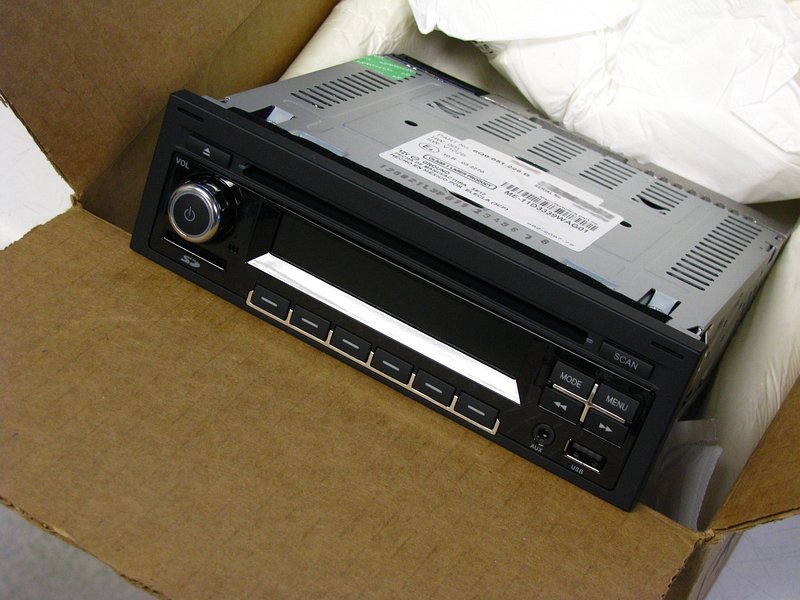
Here is the unit. It's a pretty good looking one, and it MUST be the closest match to an E30 interior that you will find while also having modern features. It isn't all that close of a match, but compared to the "alien spaceship" crap you find in the aftermarket it is pretty good.
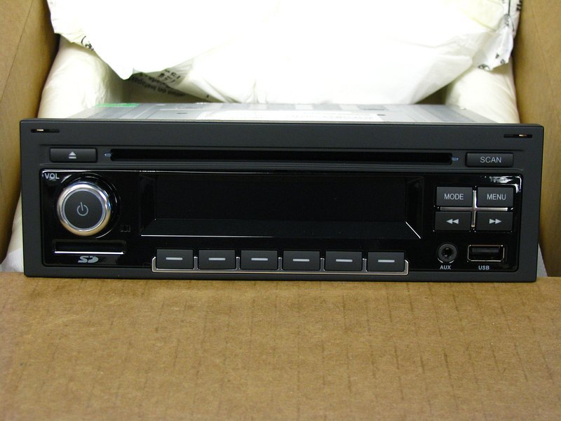
From the front.
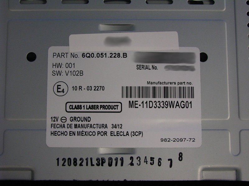
The label, in case anyone cares. Someone with Clarion connections get me the schematics please!
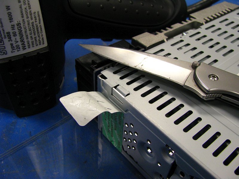
OK, time to start opening things up. Tamper label? LULZ. Set your heat gun for 200°F and gently pry. Why did I bother? No idea, considering the warranty on this thing is going to be so voided that it's past not being funny and it's actually funny again.
For the top cover, remove the 3 phillips screws and lift up the edge of the black felt tape (at bottom of photo) to release the top cover.
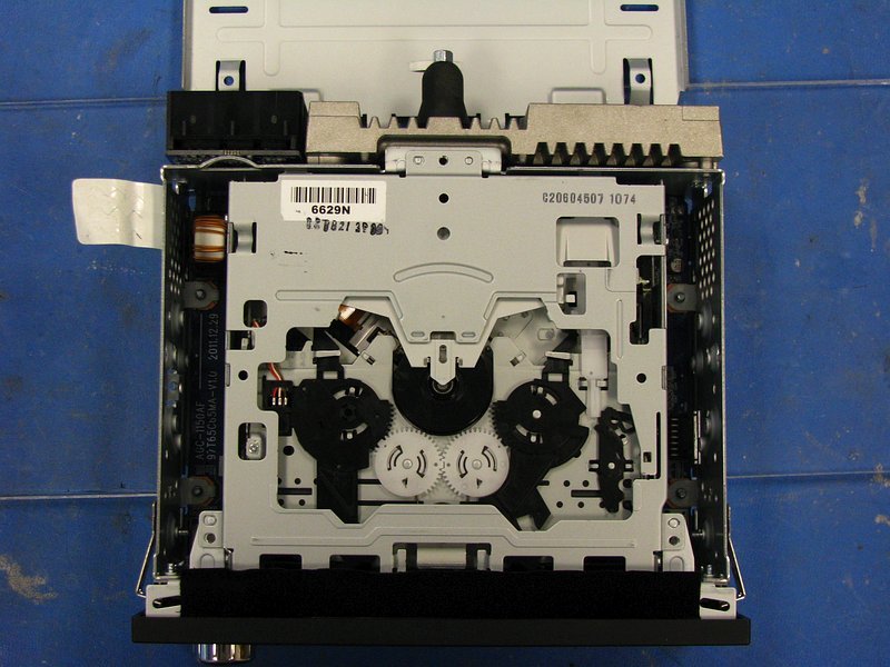
The CD transport is easily removed. Just lift gently and don't let it hang up on the felt tape's adhesive. Loosen the latches on the flat cable connector and disconnect it from the motherboard.
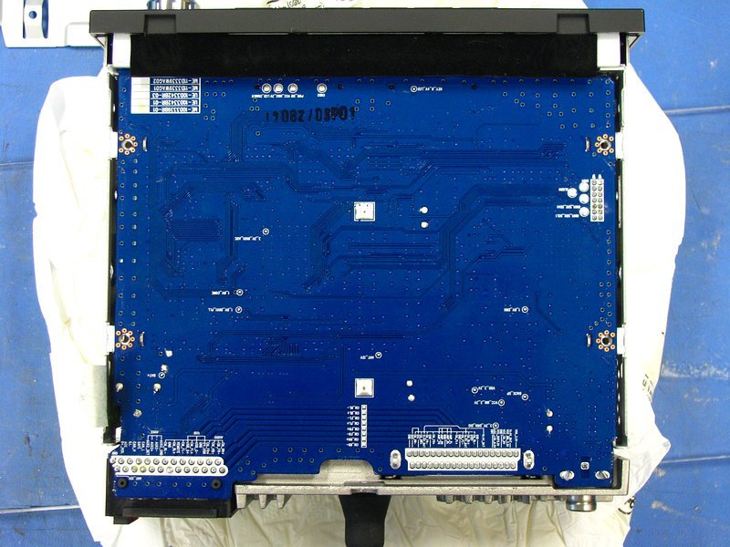
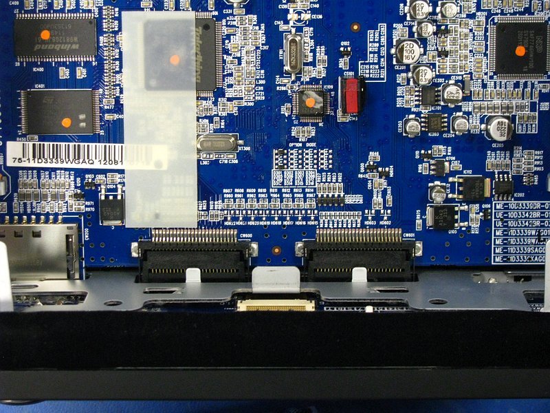
With the CD transport out, you can now see the "busy" side of the motherboard. There's actually not all that much going on in here...lots of empty space.
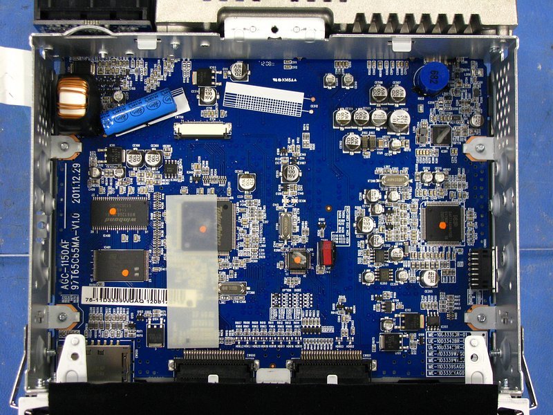
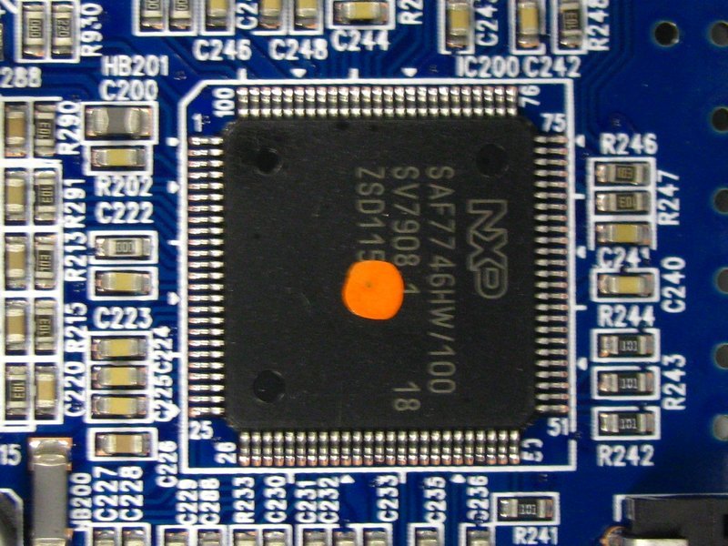
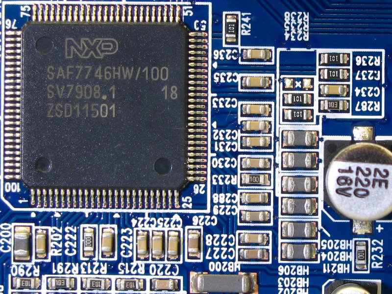
There are a few big chips down there. First up is the NXP SAF7746HW/100. This is the DSP chip that sends pre-amp audio signals to the power amp chip, and multiplexes the analog Aux-Input, CD audio, radio audio, etc. I would imagine that it also talks to the next chip that I am going to show and gets Bluetooth audio output from that.
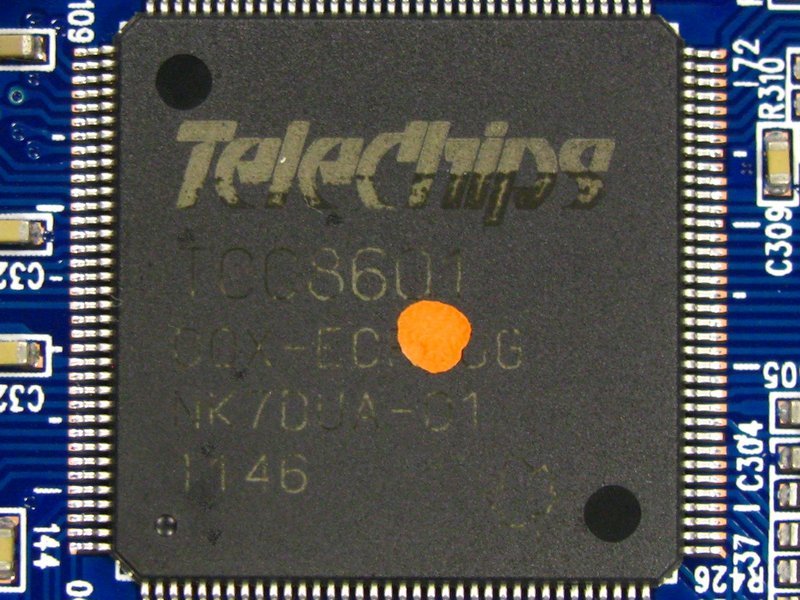
This is the "feature" chip (Telechips TCC8601). It handles USB, SD card, Bluetooth, LCD display and whatever other digital features are onboard.
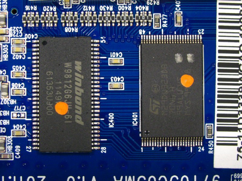
These two are related to the Telechips part. The winbond part is SDRAM and the ST part is flash memory.
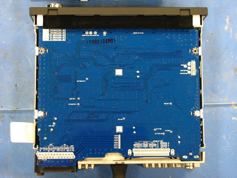
Continuing on, the bottom cover is also easy to remove. Tamper label, 3 screws and the black felt tape, just like the top.
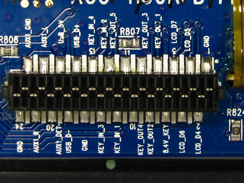
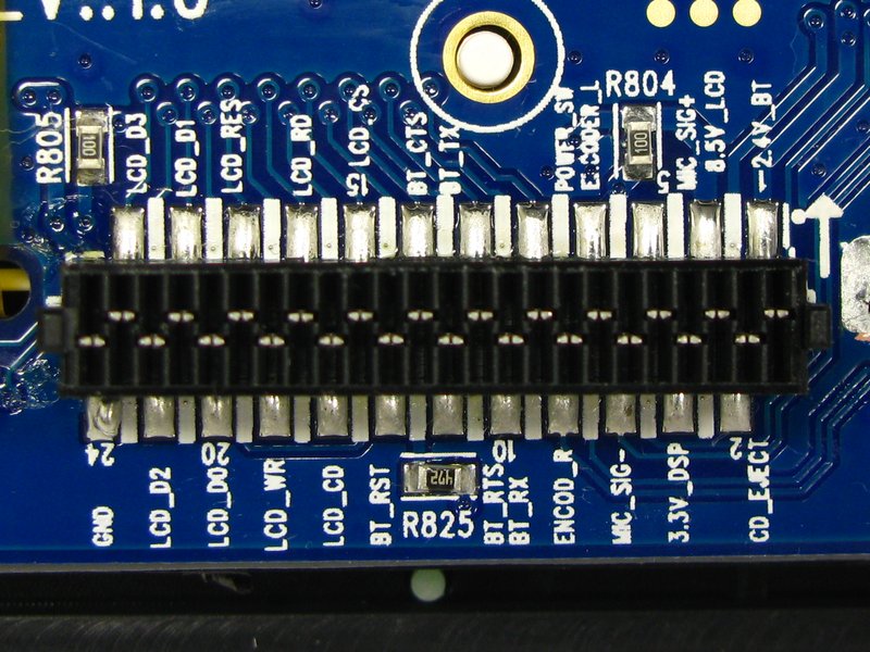
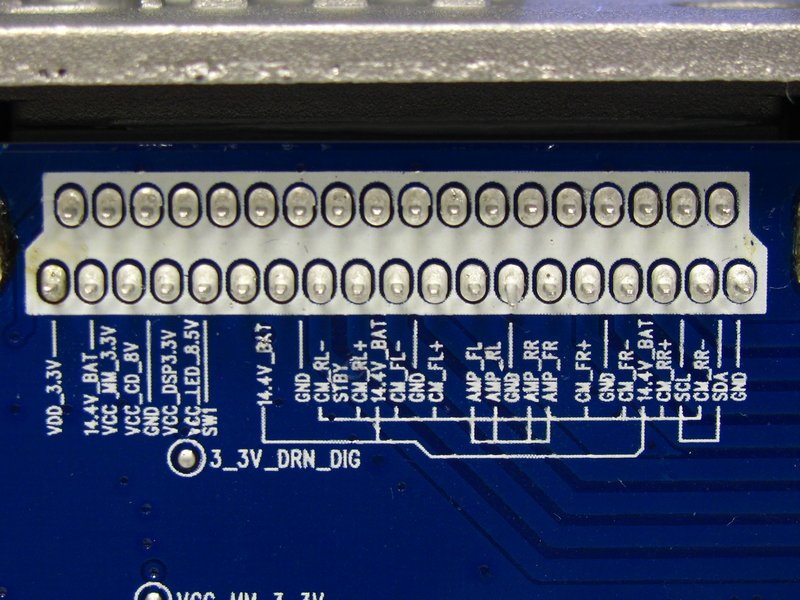
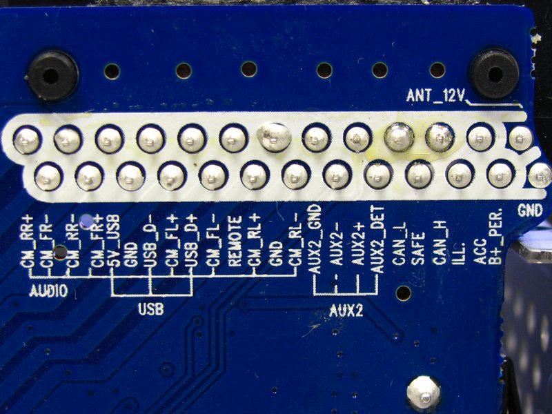
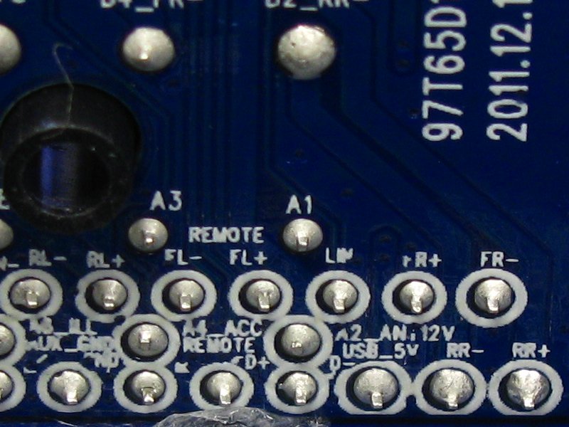
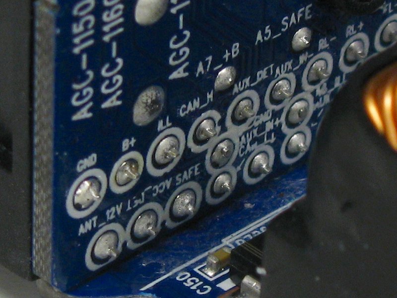
Talk about convenient. The pinouts for the big amp chip are labeled in the silkscreen.
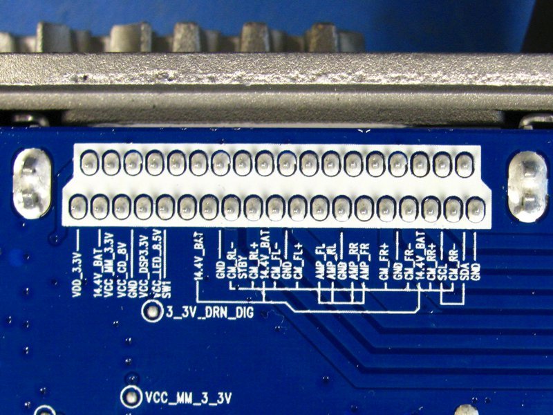
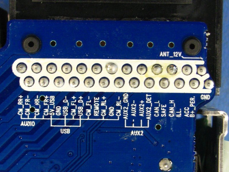
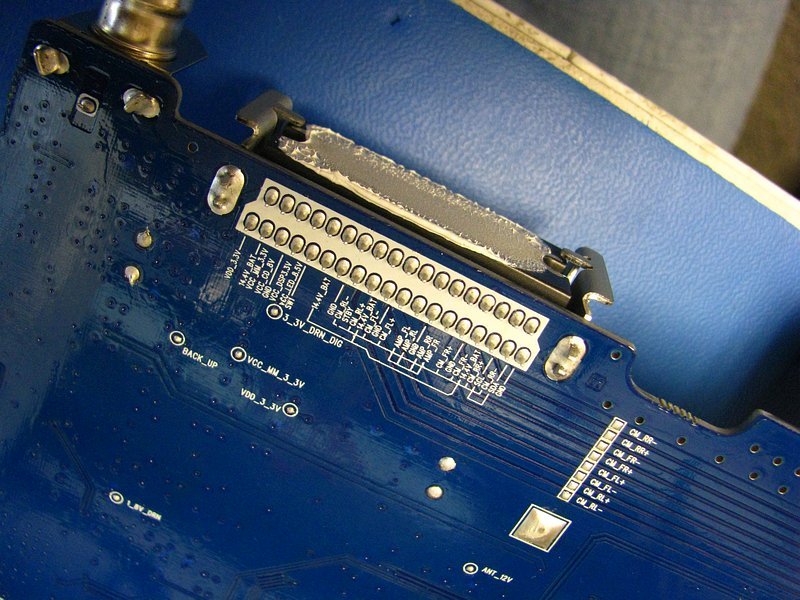
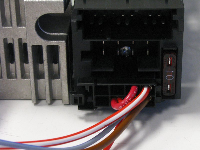
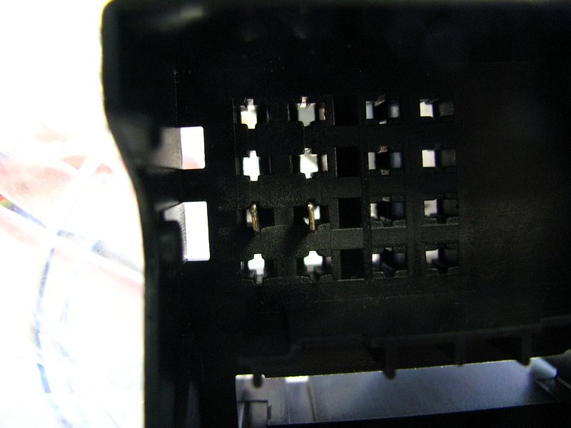
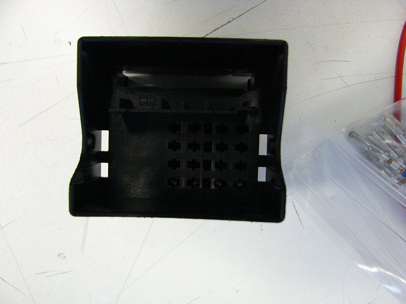
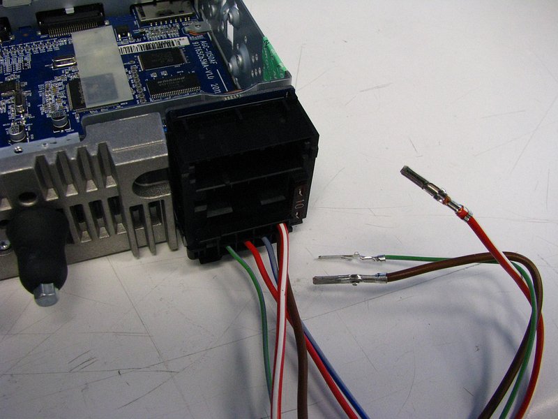
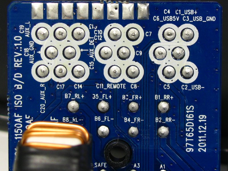
Similarly, the pins on the big modular connector board are labeled. There is some interesting stuff here. It looks like a USB connection is available back there, as well as a SECOND analog AUX input.
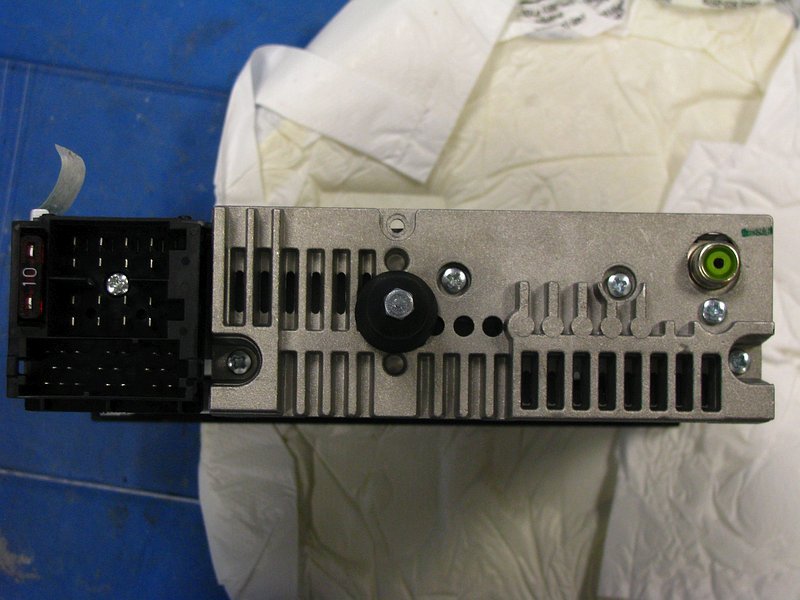
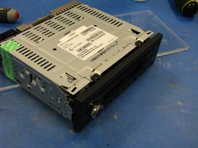
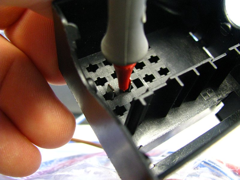
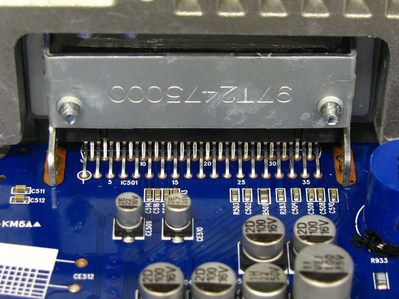
Anyway, I wanted to see what the PN was for the big amp chip, so more prying was needed. You have to remove the heat sink on the back in order to see the amp chip, and it makes removing the motherboard easier too. All the screws need to be removed, and then it comes right off. Watch out for the messy thermal paste behind the amp chip. Also, this may cause problems with thermals on that chip once you break the thermal paste bond-line, so be warned. I have access to all sorts of high-end thermal compounds at work, so I just cleaned this off and put some better stuff in when I was done.
Also remove the 2 remaining screws on the bottom of the motherboard to free it.
The 4 screw locations have little tabs that lock into the board. You have to push the board down, and then pull it backwards to disengage it from the front faceplate connectors.
The front faceplate connectors. Just pull straight back.
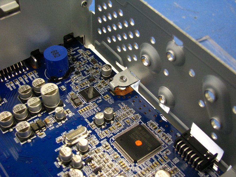
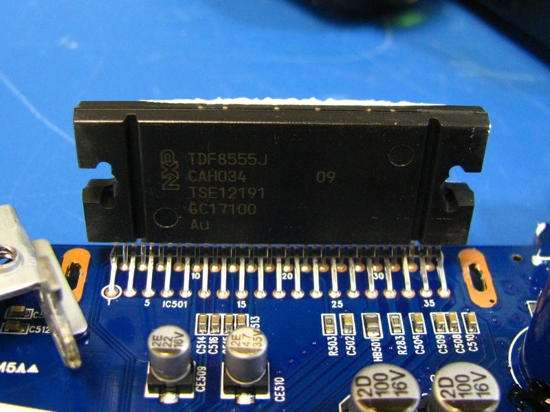
With the motherboard out and the heat sink off, there is still the bracket hiding the amp chip's part number. The bracket is soldered to the motherboard, so get ready for some heat.
With the bracket removed (and you need to be very careful because pulling on it can easily rip up the copper plating...get that solder out!) the prize is in sight. An NXP TDF8555J. It's a reasonably standard part and the datasheet is easy to get at (unlike those for the Telechips part and NXP DSP).
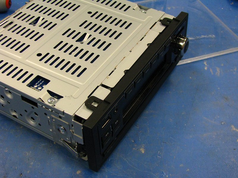
Anyway, I put the board back together and turned my attention to the faceplate. Removal is fairly easy. Remove the 2 black felt adhesive strips and carefully pry the 6 plastic tabs off of the chassis.
Here's the backside. Lots of solder flux left on here...must have been pinching pennies on assembly.
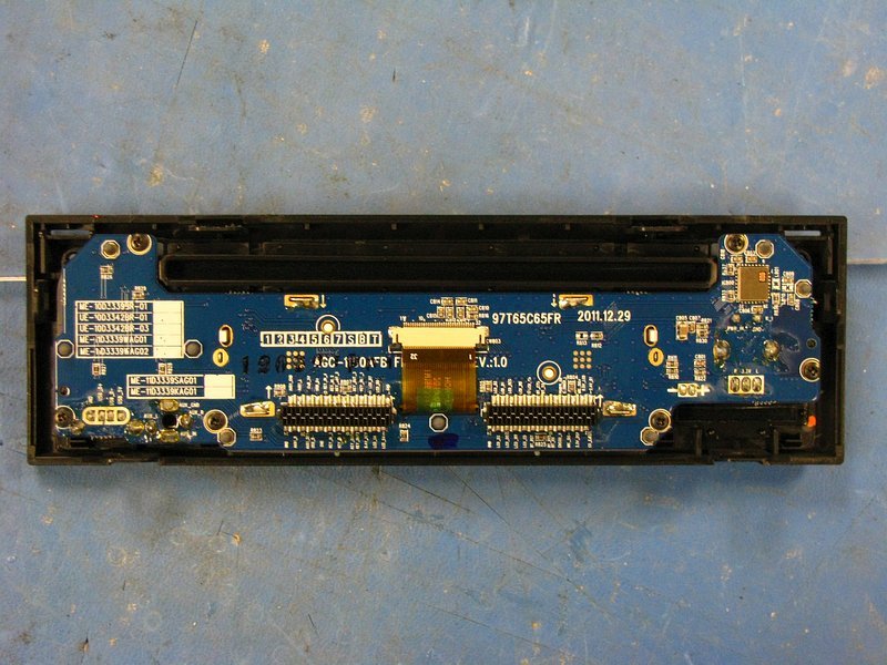
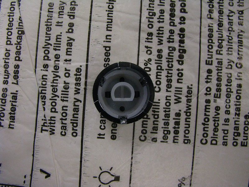
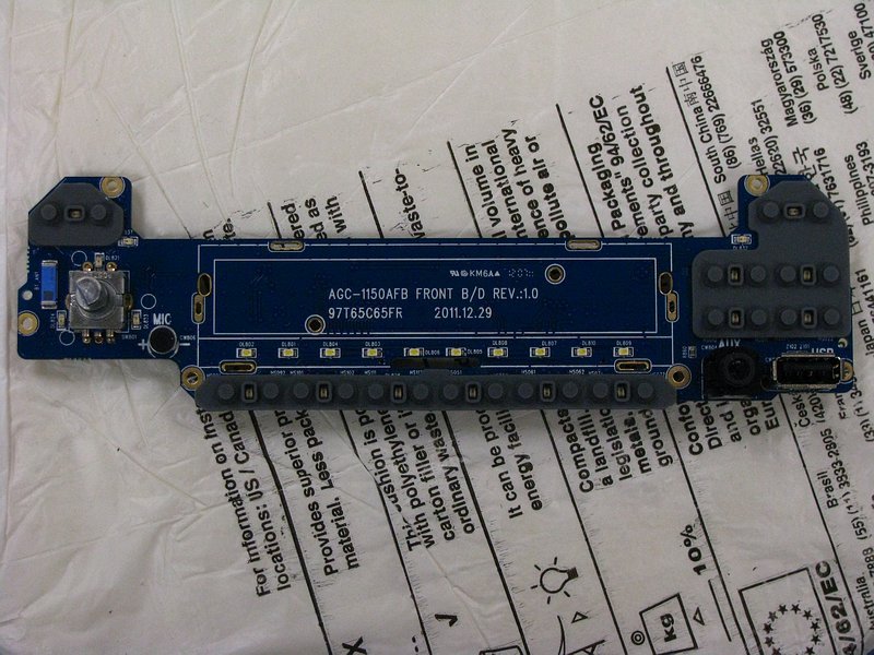
If you disconnect the flat flexible cable and remove the 6 #1 phillips screws, the PCB comes out without much trouble. Oh, and you have to remove the volume knob, which took some pretty serious pulling.
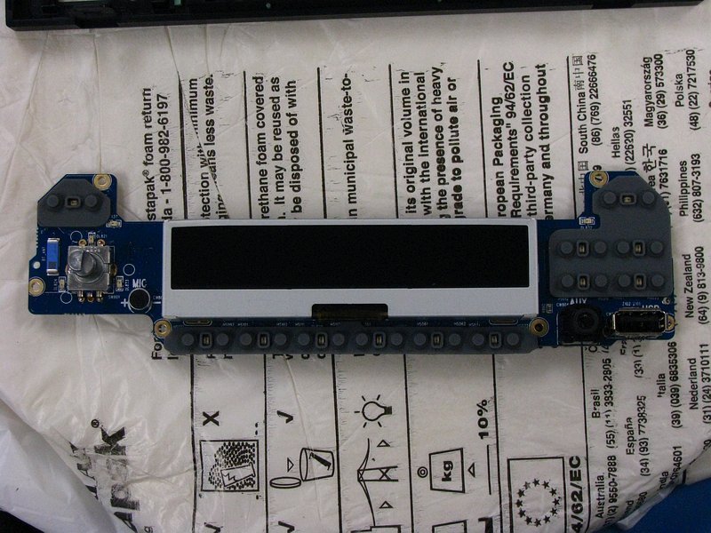
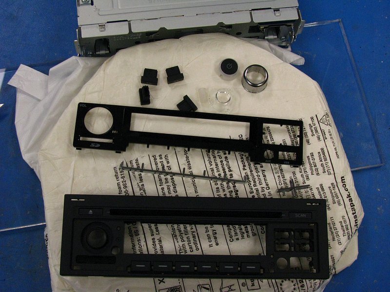
I was very happy to find that the faceplate was all snapped together. No adhesives, meaning that all the chrome bits could be removed if I wanted to paint them. Much cleaner results are possible that way. Even the volume knob was easy to take apart since it was just snapped together. I disassembled it all just to prove it could be done. Removing the chrome "cross" requires removal of the 4 buttons around it, which takes some needle-nosed pliers to squeeze the buttons' locking tabs. Paint will happen some other time, there is more important stuff to do right now.
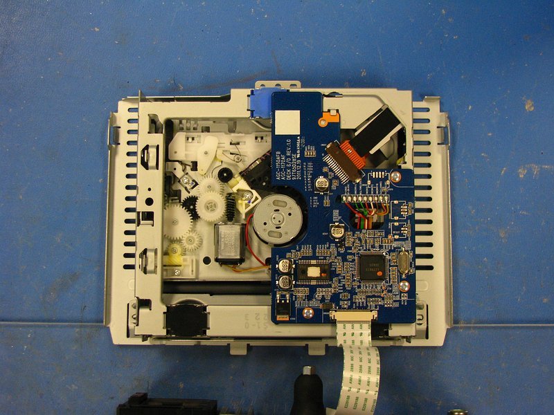
Finally, I removed the LCD module. That required de-soldering 4 large metal tabs, which again is something that you have to be careful doing both to not damage the copper pads and to not over-heat the bracket and damage the LCD. Underneath were some fairly standard white LEDs. The rest of the LEDs on the board are red, and ALL of them look pretty easy to swap out for 605nm orange ones at some point.
------------------------------
That's it for now. Overall, my impression is that this unit is built much better than most or all aftermarket (non-OE) units. I would even say that build quality is, overall, slightly better than the venerable CD43 (which is also better built than non-OE stuff). I have enough information to meet 3 of my 4 goals fairly easily, with the tricky one being dealing with the stupid system BEEP sounds. Honestly, I don't even know if this makes beep sounds when you press buttons since I have not even powered it up, but it sounded like there are beeps based on discussion in another thread. That will take some additional digging and probably some oscilloscope action to trace out. No biggie, it'll be fun either way.
More to come!
- Change the faceplate backlighting to 605nm orange to match the E30 interior
- Paint the chrome bits matte black to match the dash, and maybe the shiny black part too
- Develop "pre-amp" outputs so that this will play nicely with aftermarket amplifiers
- Disable or reduce the volume of system BEEP sounds
I know which items a certain expert audio installer / audio nut on here wants me to look at! So, anyway, it's a new project to mess with. Some of you may remember when I was reverse engineering a CD43 faceplate to work with an aftermarket radio, and while I got pretty far along, I lost interest. This seems like a more reasonable project, and easier in MANY ways.
Anyway, talk is cheap. Let's look at some pictures. Prepare your butts.
----------------------------------------------------------
Here is the unit. It's a pretty good looking one, and it MUST be the closest match to an E30 interior that you will find while also having modern features. It isn't all that close of a match, but compared to the "alien spaceship" crap you find in the aftermarket it is pretty good.
From the front.
The label, in case anyone cares. Someone with Clarion connections get me the schematics please!
OK, time to start opening things up. Tamper label? LULZ. Set your heat gun for 200°F and gently pry. Why did I bother? No idea, considering the warranty on this thing is going to be so voided that it's past not being funny and it's actually funny again.
For the top cover, remove the 3 phillips screws and lift up the edge of the black felt tape (at bottom of photo) to release the top cover.
The CD transport is easily removed. Just lift gently and don't let it hang up on the felt tape's adhesive. Loosen the latches on the flat cable connector and disconnect it from the motherboard.
With the CD transport out, you can now see the "busy" side of the motherboard. There's actually not all that much going on in here...lots of empty space.
There are a few big chips down there. First up is the NXP SAF7746HW/100. This is the DSP chip that sends pre-amp audio signals to the power amp chip, and multiplexes the analog Aux-Input, CD audio, radio audio, etc. I would imagine that it also talks to the next chip that I am going to show and gets Bluetooth audio output from that.
This is the "feature" chip (Telechips TCC8601). It handles USB, SD card, Bluetooth, LCD display and whatever other digital features are onboard.
These two are related to the Telechips part. The winbond part is SDRAM and the ST part is flash memory.
Continuing on, the bottom cover is also easy to remove. Tamper label, 3 screws and the black felt tape, just like the top.
Talk about convenient. The pinouts for the big amp chip are labeled in the silkscreen.
Similarly, the pins on the big modular connector board are labeled. There is some interesting stuff here. It looks like a USB connection is available back there, as well as a SECOND analog AUX input.
Anyway, I wanted to see what the PN was for the big amp chip, so more prying was needed. You have to remove the heat sink on the back in order to see the amp chip, and it makes removing the motherboard easier too. All the screws need to be removed, and then it comes right off. Watch out for the messy thermal paste behind the amp chip. Also, this may cause problems with thermals on that chip once you break the thermal paste bond-line, so be warned. I have access to all sorts of high-end thermal compounds at work, so I just cleaned this off and put some better stuff in when I was done.
Also remove the 2 remaining screws on the bottom of the motherboard to free it.
The 4 screw locations have little tabs that lock into the board. You have to push the board down, and then pull it backwards to disengage it from the front faceplate connectors.
The front faceplate connectors. Just pull straight back.
With the motherboard out and the heat sink off, there is still the bracket hiding the amp chip's part number. The bracket is soldered to the motherboard, so get ready for some heat.
With the bracket removed (and you need to be very careful because pulling on it can easily rip up the copper plating...get that solder out!) the prize is in sight. An NXP TDF8555J. It's a reasonably standard part and the datasheet is easy to get at (unlike those for the Telechips part and NXP DSP).
Anyway, I put the board back together and turned my attention to the faceplate. Removal is fairly easy. Remove the 2 black felt adhesive strips and carefully pry the 6 plastic tabs off of the chassis.
Here's the backside. Lots of solder flux left on here...must have been pinching pennies on assembly.
If you disconnect the flat flexible cable and remove the 6 #1 phillips screws, the PCB comes out without much trouble. Oh, and you have to remove the volume knob, which took some pretty serious pulling.
I was very happy to find that the faceplate was all snapped together. No adhesives, meaning that all the chrome bits could be removed if I wanted to paint them. Much cleaner results are possible that way. Even the volume knob was easy to take apart since it was just snapped together. I disassembled it all just to prove it could be done. Removing the chrome "cross" requires removal of the 4 buttons around it, which takes some needle-nosed pliers to squeeze the buttons' locking tabs. Paint will happen some other time, there is more important stuff to do right now.
Finally, I removed the LCD module. That required de-soldering 4 large metal tabs, which again is something that you have to be careful doing both to not damage the copper pads and to not over-heat the bracket and damage the LCD. Underneath were some fairly standard white LEDs. The rest of the LEDs on the board are red, and ALL of them look pretty easy to swap out for 605nm orange ones at some point.
------------------------------
That's it for now. Overall, my impression is that this unit is built much better than most or all aftermarket (non-OE) units. I would even say that build quality is, overall, slightly better than the venerable CD43 (which is also better built than non-OE stuff). I have enough information to meet 3 of my 4 goals fairly easily, with the tricky one being dealing with the stupid system BEEP sounds. Honestly, I don't even know if this makes beep sounds when you press buttons since I have not even powered it up, but it sounded like there are beeps based on discussion in another thread. That will take some additional digging and probably some oscilloscope action to trace out. No biggie, it'll be fun either way.
More to come!


Comment