
Hey everyone,
To complement my ongoing motor build I have also been working on a custom instrument cluster design. Over the last six or so months I have been spending a fair bit of spare time working towards a replacement for the e30 instrument cluster that essentially achieves the following:
At a high level, the PCB design includes the following:
Anyway, here are some screenshots for those that may be interested. Currently wrapping up the EDA portion of the work, and I have some pretty pictures to show (note that some silkscreen labels and such need a final cleanup pass... I may change connector footprints so these aren't all done yet). If there is any serious interest from any resident EE's I will be happy to put up a schematic (try not to make too much fun of me, I write firmware for a living, not design PCBs):
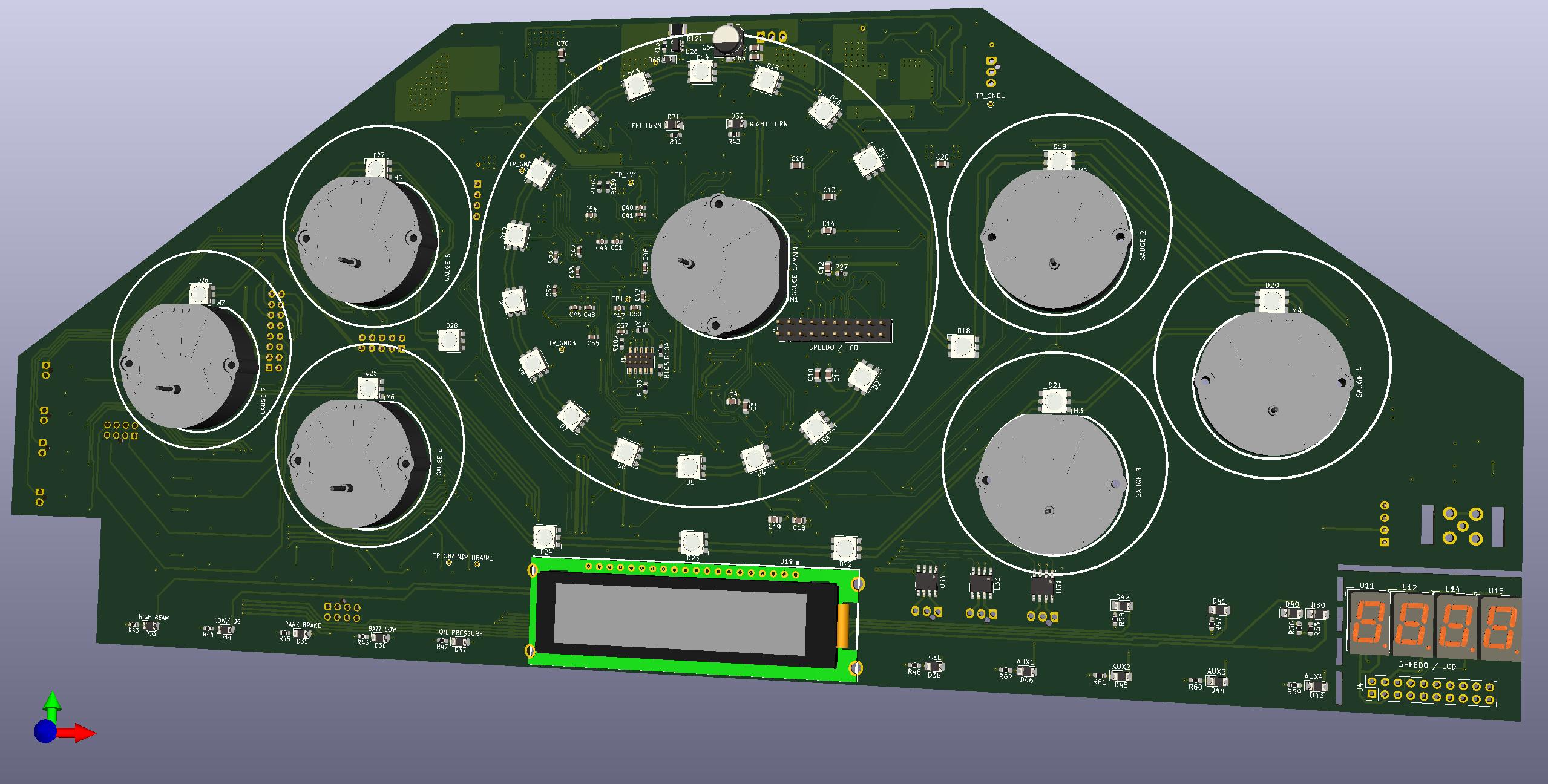
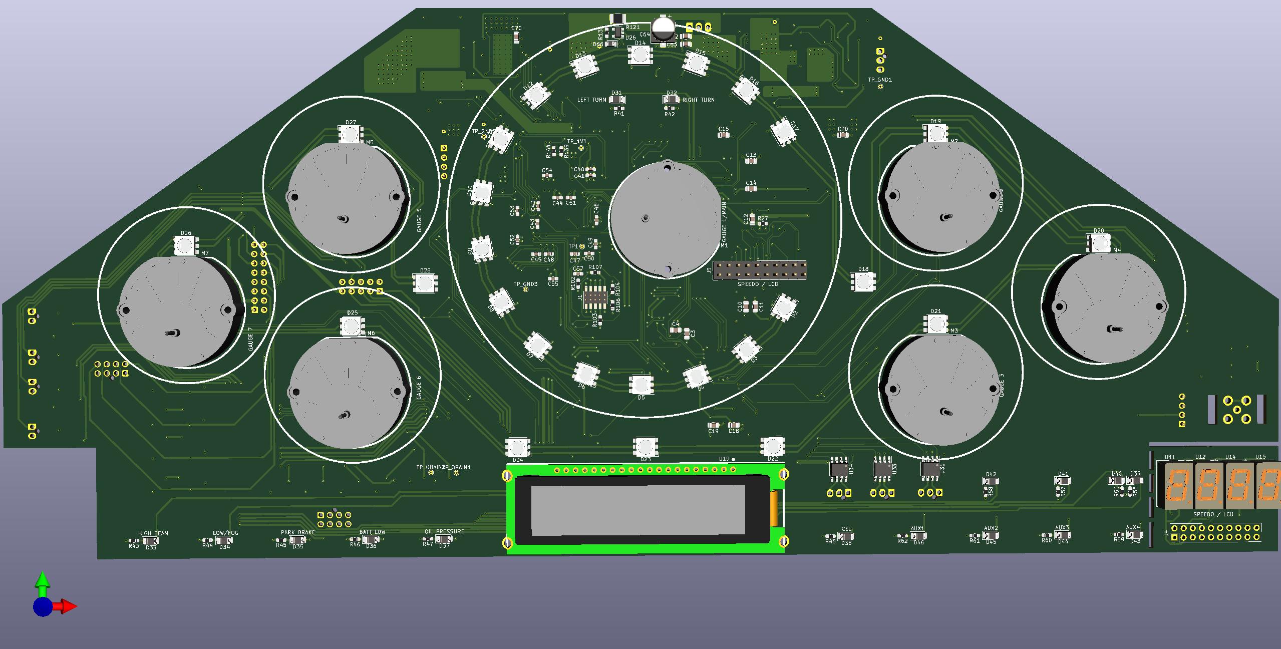
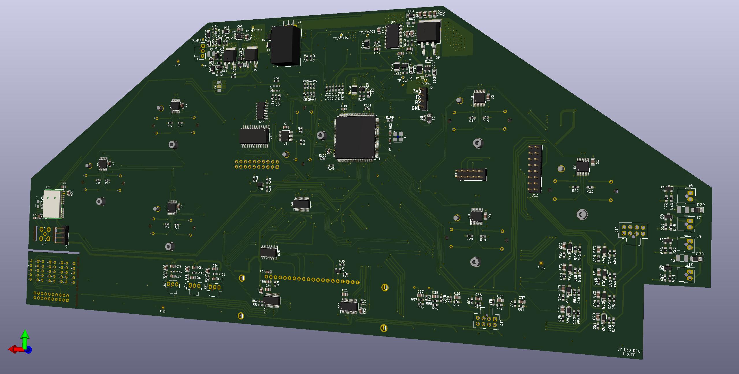
Front and back rendered PCB views (note the lack of mounting holes and some connector models. Also, stepper motors will end up mounted slightly 'bent' so they will probably stand off from the board and bit and point slightly inwards. The speedo on the bottom right is cutoff after PCB production and mounted overtop the tachometer on the connector labeled 'speedo/lcd').
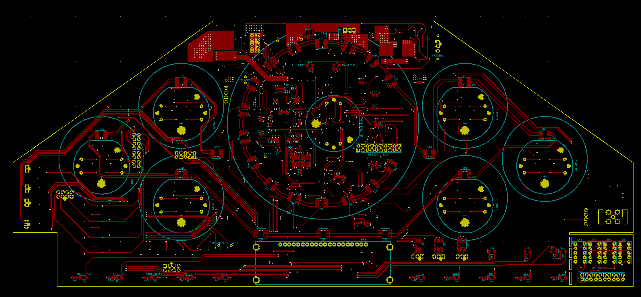
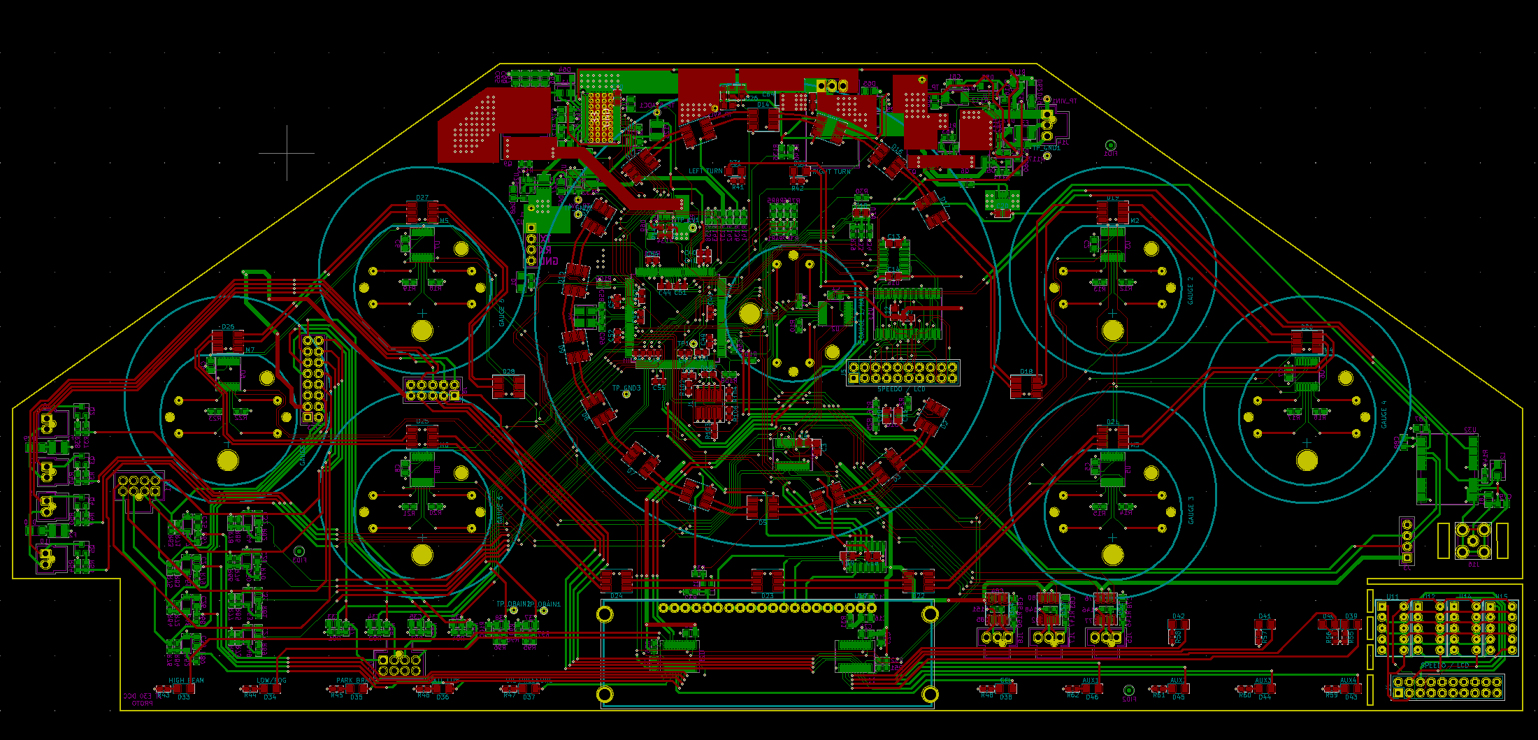
And I included a few EDA snapshots so you can see the mess of wiring in all its glory. Note that internal copper planes are hidden (board is 4 layer).
top:
bottom

both. Sweet, savory chaos
In terms of actual costs, BOM is running approximately ~400 Canadian at the moment, in very low volumes and fully populated (using slow turn PCBs from china, prices based on their qoute estimation tool). This may change a bit after prototyping, and does not include assembly, which realistically if mass produced would be a pain in the ass because the board is double sided. If I do get everything working and firmware development goes along fairly smoothly I would probably be willing to let the design and firmware go cheaply, but we will see. First and foremost I want to get it running on my build.
To complement my ongoing motor build I have also been working on a custom instrument cluster design. Over the last six or so months I have been spending a fair bit of spare time working towards a replacement for the e30 instrument cluster that essentially achieves the following:
- Maintains a primarily analog look and feel.
- Connects up to my MS3 over CAN and significantly reduces wiring requirements.
- Implements a fancy rev-matching assist scheme so I always sound like a pro. Obviously this is by far the most important point.
At a high level, the PCB design includes the following:
- Seven analog gauge pods (six 'small' and one 'large'). For reference, they are sized almost identically to the existing e30 large and small gauges.
- The large gauge is intended as a tachometer. Smaller gauges will be providing whatever information I desire, but at this point in time CLT, MAP, oil temp/press, etc. are the sorts of things I will be assigning to them.
- Backlit ring of multi-color LEDs around the central gauge, intended to provide at-a-glance information about ideal engine speeds for rev-matching up and down gears. Basically I will be taking information about the current gear lever position, clutch pedal position, engine speed and wheel speed to display various obnoxious colors on the tachometer indicating where the sweet spot is for down and up shifting into available gears.
- Individual multi-color backlighting for each smaller gauge, as well as various points on the PCB. This basically means that aside from the 7-segment speedometer, I can change the cluster backlight color to suite my mood.
- A 4 digit 7-segment LCD that is intended for use as a speedometer. This will sit 'inside' the tachometer.
- A grey scale multicharacter OLED for other bits of information, such as vehicle odometer, a clock, and any important status bits from the ECM.
- A mounting point for a U-BLOX module (specifically the NEO-M8U). Been working with this guy a fair bit lately and it would be relatively straightforward at this point for me to setup and use to provide gps, and more importantly, vehicle acceleration information. Realistically this isn't the best position for the module (vehicle center of mass or above rear axle would be ideal), so we will see if I actually use it or not (but eh, I had a free UART and some empty space, so...).
- I also have roughed out a set of adapters (I am still flip flopping a bit on connector setup) that will support an I/O adapter board mounted to the back. The idea with this is that if there is enough interest I can fabricate up a small PCB that includes the stock E30 connectors and some minimal signal conditioning electronics (for whichever model) so you would theoretically not be stuck running an MS3 and CAN bus to use the cluster.
- 3 separate CAN bus connectors.
- Stand alone real-time clock.
- Lots of single LED indicators. You can see them labeled as LEFT TURN/RIGHT TURN/HIGH BEAM/etc. in the pictures below, but the reality is they are completely mappable so don't get attached to the labels.
- There isn't a peizo element or any relays, I am on the fence about whether I should add this because right now it cannot even beep at you.
- I don't have an ambient light sensor on the board, but this data will be coming in over the CAN bus and can then be used for automatic brightness adjustments.
- In terms of components, *almost* everything is automotive rated. Multicolor LED's and displays are a bit of a pain in the ass, the temperature ranges on them make me uncomfortable (for reference, I live in Canada, so -30C is a real threat).
- Some other goodies that may or may not make the cut after the prototyping stage.
- Everything is being driven by a texas instruments TMS570LS3137 processor, which probably doesn't mean anything to most people but I decided to include that tidbit anyway. All inputs and outputs are piped through the MCU (microcontroller unit), there is a collection of analog and digital (both steady state and PWM/Pulse Train) capable inputs exposed. Since everything goes through the MCU, theoretically I can program the board to light up like a christmas tree and shake all the gauges in fury if you blow a shift, or more realistically change which LEDs and gauges display which data depending on how my e30 build evolves.
Anyway, here are some screenshots for those that may be interested. Currently wrapping up the EDA portion of the work, and I have some pretty pictures to show (note that some silkscreen labels and such need a final cleanup pass... I may change connector footprints so these aren't all done yet). If there is any serious interest from any resident EE's I will be happy to put up a schematic (try not to make too much fun of me, I write firmware for a living, not design PCBs):
Front and back rendered PCB views (note the lack of mounting holes and some connector models. Also, stepper motors will end up mounted slightly 'bent' so they will probably stand off from the board and bit and point slightly inwards. The speedo on the bottom right is cutoff after PCB production and mounted overtop the tachometer on the connector labeled 'speedo/lcd').
And I included a few EDA snapshots so you can see the mess of wiring in all its glory. Note that internal copper planes are hidden (board is 4 layer).
top:
bottom
both. Sweet, savory chaos
In terms of actual costs, BOM is running approximately ~400 Canadian at the moment, in very low volumes and fully populated (using slow turn PCBs from china, prices based on their qoute estimation tool). This may change a bit after prototyping, and does not include assembly, which realistically if mass produced would be a pain in the ass because the board is double sided. If I do get everything working and firmware development goes along fairly smoothly I would probably be willing to let the design and firmware go cheaply, but we will see. First and foremost I want to get it running on my build.


Comment