
My screenshot is of the composite log instead of the tooth log, so that's why it looks a little different. The red graph along the bottom is the de-sync counter. Next time I fire up the car I'll grab a tooth log for comparison, but basically it'll show the missing teeth section as being too tall of a bar and then only one too few short bars in between.
-
-
Oh and to the OP, your graphs certainly look like your problem is not seeing the missing teeth gap properly (sorta opposite my problem), but for this the 18k (or 10k) resistor in series with the VR+ wire should be the first fix you try if you haven't already!Comment
-
Here's my tooth log. You can see the extra long gap in the middle that's then only followed by 57 instead of 58 teeth. Also, this problem seems to worsen as engine temperature increases, which I really can't explain. Revs fine to redline dead cold (though I don't like to do that!) Here it's about 190 and cutting out around 6000 RPM, and fully warm around 210 it cuts out at 4500-5000 RPM.
Hmm, attachment not working, so here's a link to the screenshot:
On a final note, is the small wave along the normal teeth just a bit of runout on the wheel itself?Last edited by Austrianvespaguy; 06-17-2019, 07:19 PM.Comment
-
I was under the impression that the resistor on the board was 25k, but after reviewing the schematics realized it was actually only 5k. I added a 10k resistor and that seems to have fixed the issue with the CPS.
Sent from my iPhone using Tapatalk1988 E30 325iC
sigpicComment
-
Good stuff! Glad we were able to get you're solved! Now if I can just figure out my issue. . .Comment
-
Since yours is temperature dependent I would consider that it could be the toothed wheel itself. It is mounted on a rubber damper that degrades over time. When your car is running does it look like the toothed wheel has a lot of run out? Have you tried other/new CPS's? Have you ohm tested yours both at the sensor and at the 55 pin connector?Originally posted by Austrianvespaguy View PostComment
-
Ah, I didn't realize it was mounted to the rubber part of the pulley, good call! I have checked it's resistance (575 ohms at the sensor connector) but I'll verify at the 55 pin connector also. My gap is pretty small, about 0.5mm and no I don't really see much runout, but I do see what I think is a very small amount in the tooth logger.Comment
-
Well a little more info for the general knowledge-base here; I'm using the DIYPNP board w/Microsquirt card, and it has TWO different VR signal conditioners on it. The Microsquirt uses a MAX9926 chip, and the DIYPNP board has an extra optional LM1815 chip. The MAX9926 wants the ~10k resistor on the input for noise reduction, and the LM1815 wants the ~18k ohm resistor on the input to lower the current that it needs to sink. I made the small mistake of installing the 18k resistor with the MAX9926 circuit, and I think it was blocking too much of the signal. Just switched down to the more proper 10k, and things are certainly improved. I'm not closing the book on this one just yet, only tested briefly and think I still dropped once or twice at redline, so might go with an even lower resistance, but looks like I'm on the path to improvement now!Comment
-
I HAVE SOLVED THIS FOR EVERYONE!!!
But the solution varies depending on exactly which Megasquirt setup/VR condition circuit you have, so make sure you understand this! @Malcolm206, as I understand it you're using MICROsquirt v3, and if that's correct, you are not done yet! So here's the rundown:
1.) If you are using an LM1815 chip for as your VR conditioner (found as an optional extra on some PCBs such as the DIYPNP), then you want the 18k resistor in series with the VR+ sensor wire (to limit the current that the IC needs to sink).
2.) If you are using MEGAsquirt 3.0 or 3.57, then you want the 10k resistor in series with the VR+ sensor wire (to filter out noise at higher RPMs).
3.) If you are using MICROsquirt, then you want a 10k SHUNT resistor that goes BETWEEN the VR+ and VR- sensor wires! (<- This really solved my problem and is the proper setup for the MAX9926 chip on the Microsquirt board)! See page 47 of the Microsquirt Maunal here!
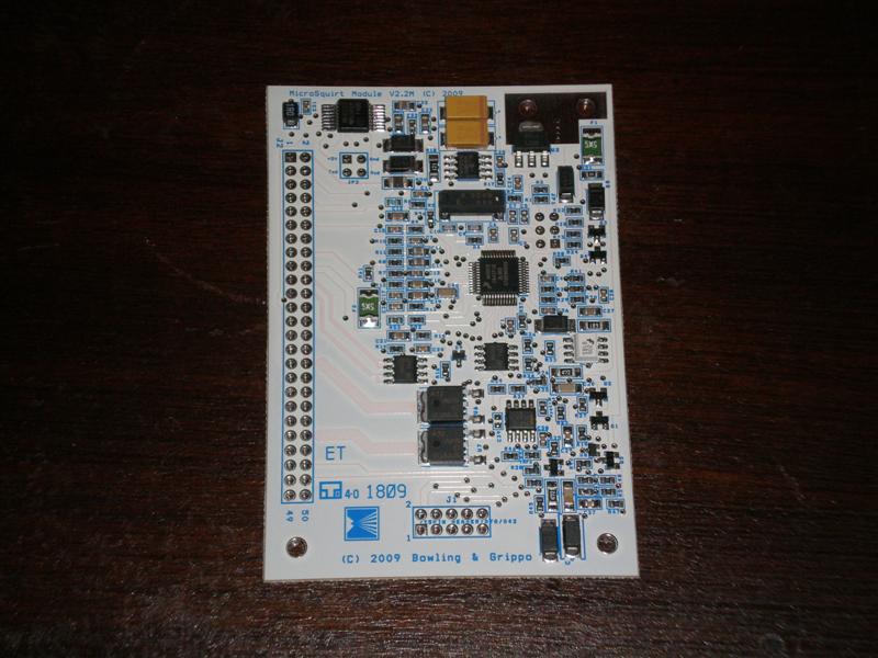
Malcolm and DigitalWave, I'd suggest you double check which VR condition circuit you are using; if you have the white Mirosquirt daughter card that looks like this:
THEN YOU NEED THE SHUNT RESISTOR IN SOLUTION 3!!!Comment
-
There are a variety of resistors that will "work." I doubt this will solve everyone's problem, as there are a lot of reasons it could be happening.
FWIW once I replaced my CPS with a new metal one it fixed my issue. I can and have used a 10k, 18k, 20k, and 25k resistor and all of them worked fine with the new CPS. My MS is Microsquirt-based.Comment
-
So yes there are various combinations that can probably made to work, but I now completely understand these circuits and can assure you that using a single inline resistor with the Microsquirt VR conditioning circuit is just plain WRONG (even if it 'works'). The reason for this is the MAX9926 chip uses differential input, meaning that it's looking at BOTH the VR+ and VR- signals relative to each other and NOT relative to ground (aka single-ended input, which is how the LM1815 works). So putting extra resistance on one signal and not the other will skew the zero-crossing reading, which is bad. The shunt resistor between the two wires keeps both signals 'even' but still drops the peak voltage generated at higher RPM speeds.
Also the MAX9926 chip is really the best of the bunch; so if you set it up correctly with the shunt resistor, it WILL work for everybody with that setup, and it will take out the touchiness of individual sensors, air gaps, etc. It's a really robust circuit; not that you want to bother, but with the shunt resistor I'll bet you it would also work perfectly with your OLD sensor too!
EDIT: And Malcolm was really on the right track at first by bridging the SB2 on the board to use its built-in shunt resistor, but I suspect that 5k resistor is intended for 'other' trigger wheels and the 60-2 wheel needs the 10k resistor as indicated in the Microsquirt manual. Re-reading Malcolms last post, I think he has done things correctly by putting in a 10k shunt resistor in place of the 5k, but hopefully he'll confirm this for us!Last edited by Austrianvespaguy; 06-19-2019, 01:10 PM.Comment
-
I am getting break up around 4500rpm as well and I see everyone mentioning adding a resistor. But I really haven't seen anyone mention how to add the resistor. Above post mentions inline, am I really cutting the cps wire and adding it in there? I'm fine with that, but I want to be sure before I do so.AWD > RWDComment
-
The above post says "series" and "shunt". Series is cut the wire and add in-line, shunt is cut both wires and bridge bare wires with resistor, but keeping them isolated from each other.Originally posted by Kershaw View Post
What sensor and what air gap are you using? A lot of the newer plastic sensors have a resting resistance of ~900 ohms, yet still work with the stock ECU just fine. Haven't logged the differences, but often just simply messing with the air gap has solved this for me. Over the years, even in a professional installation setting, I have not installed a single resistor on an m20 with MS.Comment
-

I suppose I could try cleaning it a bit. Not sure how much closer I can scoot the sensor but I will try playing with the air gap.
Too bad you're not closer. I really don't want to deal with it. I just want to race it. I don't have the time anymore to chase down things like this with work dominating my life now.AWD > RWDComment
-
It takes no time. Use a 1/4" 13mm short socket on a 1" long 1/4" extension and it will fit behind everything in situ. Loosen the bottom bolt a turn, and just loosen the top a smidge. The bracket rotates on the top screw, and most likely the sensor will get sucked into the relcutor wheel from the magnet. Then I will slip a business card between a tooth and the sensor, and tighten it back up. If that's not the issue, check to make sure the wire isn't rubbing the water pump, and that it isn't breaking where the wire meets the sensor. We don;t even play on the race cars anymore. We buy a new OEM BMW sensor (up to $200 clams this year), and toss them as soon as the wire starts getting stiff. Nothing worse than chasing issues at the track.
EDIT: And YES, clean that thing. Those ferrous shards can cause issues.Comment


Comment