Announcement

Collapse
No announcement yet.

VGT M20 Build - HE351VE

Collapse
X
 
  • Filter
  • Time
  • Show
Clear All
new posts

    VGT M20 Build - HE351VE

    Posting with a new account, as my old one isn't much of a loss (hhspunter).

    Been working on getting my e30 running again after a few years decommissioned due to a mostly-dead turbo and procrastination. Snagged a used HE351VE on Craigslist a few years ago with dreams of stuffing it into the e30, and quickly realized it would be a big project due to the... big turbo. For those not familiar, it's from he 2008-2012(?) Dodge 2500/3500 with the 6.7L Cummins. 60mm compressor inducer and turbine exducer, if I measured correctly, so not a giant-power turbo, but physically enormous due to the VGT nozzle and actuator.

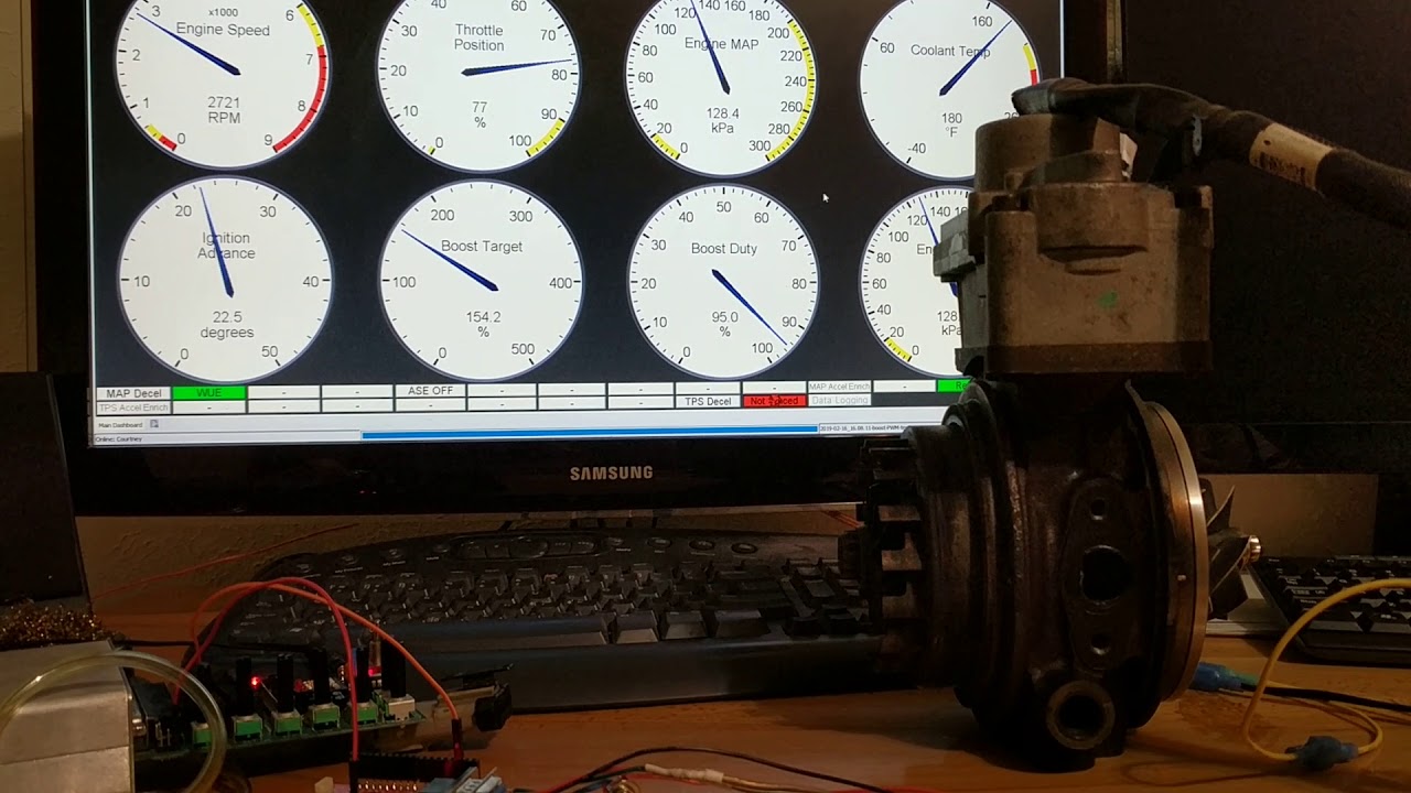
    My M20 is essentially all stock parts, save for head studs and a Enem Z45 turbo cam. The goal with this setup is to make good power on reasonable boost (1bar or so). The cam helps a ton with that from numbers I've seen, and I am hoping the VGT gives a bit more. Depending on who you ask, the nozzle area can change from a couple cm^2 to 25cm^2, and the compressor is pretty similar to HX40 I think... So compressor should be somewhat reasonably sized, and the turbine will get the turbo to spool about as aggressively as anyone could hope for, but most importantly to me, get out of the way and improve VE up top.

    The major challenge: the size. Here it is next to a Mistubishi 20g, the turbo I was running before:Click image for larger version

Name:	IMG_20191127_000612-1280x960.jpg
Views:	1973
Size:	73.8 KB
ID:	9891823​​​​​​​

    #2
    No one makes an M20 manifold for this turbo, so I knew I'd have to make one. The most critical thing was figuring out how to get the turbo positioned and all the parts clocked in a way that it would actually fit in the engine bay with as much (or any) clearance as possible. I'm running solid aluminum engine mounts, which helps here because the engine won't be moving much. This also means the turbo position *relative to the exhaust ports/flange* is the critical thing.

    So I started by building a simple wooden mock-up of a manifold that would get the turbine flange in the right place relative to the head flanges. It took a few iterations, and I ended up with this position:
    Click image for larger version

Name:	IMG_20191022_202902_309.jpg
Views:	1856
Size:	95.3 KB
ID:	9892258

    Comment


      #3
      A major design constraint I imposed on myself was to end up with equal length runners. The benefit of equal length could be debated, but it's what I wanted for sound, if anything. Also for the challenge of actually designing them. Much, much work was done in CAD, and this was one of the earlier iterations:
      Click image for larger version

Name:	IMG_20191022_191832_01-1012x759.jpg
Views:	1779
Size:	60.1 KB
ID:	9892261
      After a while lot of CAD work, and quadruple-checking clearances, ended up with the following 6-2-1 final design. Primaries are equal length to within 0.5mm, and secondaries the same. After considering options, decided to add the external wastegate feed to the turbine housing, mostly due to packaging.
      Click image for larger version

Name:	PhotoPictureResizer_191215_171528550-1008x756.jpg
Views:	1767
Size:	65.9 KB
ID:	9892262

      Comment


        #4
        The benefit of having the manifold fully designed in CAD is that there should, in theory, be no fiddling around with tube fitting. If I could manage to cut the weld elbows to the model specs, it should go together relatively easily with good fitup. The major aspect of this that I can't at least control directly is the tolerances of the weld elbows... But I was hoping I could at least account and adjust for them. In regard to that, the way I actually measured and marked the cuts would be critical to getting the accuracy needed. I'm happy to share more details of that process if anyone is interested.

        I decided to make the manifold from mild steel, biggest reasons being my lack of welding experience and skill (didn't want to end up cooking stainless, rendering it useless), ease of cutting, and lower thermal expansion (so maybe less likely to crack). In hindsight, I probably should have gone with stainless because just cleaning the black painted coating from the weld elbows added an enormous amount of work.

        The good news was that the cuts came out fantastic, and while it was super fiddly getting the manifold tacked up, I didn't have to go back and adjust a single one of the cuts. Fitup was excellent, with zero gap at most joints, and generally less that 1/16" gap on the worst joints (sch 40 pipe has >1/8" wall thickness). I also made a substantial jig from 3/8" and 1/2" plate to help mitigate warpage. Flange placement was taken from the CAD model.
        Click image for larger version

Name:	PhotoPictureResizer_191215_172821577-1008x756.jpg
Views:	1783
Size:	69.0 KB
ID:	9892273
        Click image for larger version

Name:	IMG_20191123_190216-1012x759.jpg
Views:	1787
Size:	63.5 KB
ID:	9892274
        Click image for larger version

Name:	IMG_20191124_132505-1012x759.jpg
Views:	1776
Size:	65.3 KB
ID:	9892275

        Click image for larger version

Name:	PhotoPictureResizer_191215_181954734-1008x756.jpg
Views:	1783
Size:	70.7 KB
ID:	9892276

        Comment


          #5
          Did the welds in a single pass, around 110-120amps if I remember right. Not always full penetration, but close to it, and in sch 40 that should be stout enough. I went through a lot of fill rod. Tube ends were beveled to about 35-40deg, with about 1/32" land. Other than a couple spots inside the valleys of the 3-1 collectors, I was pretty happy with how the welds came out. Managed to keep the heat in check, so if for some reason I decide to make another manifold at some point, I'm pretty confident I could do a good job with stainless and save myself a ridiculous amount of prep work (since the elbows and pipe won't have coatings, mill scale, and rust to deal with).

          This will get ceramic coated to help with heat and prevent corrosion. Also, the placement in the engine bay is about as best of a compromise as I could manage in regards to heat. The VGT actuator does not help here.

          Click image for larger version

Name:	IMG_20191125_192509~2.jpg
Views:	1788
Size:	47.7 KB
ID:	9892278

          Click image for larger version

Name:	IMG_20191127_001452-1012x759.jpg
Views:	1809
Size:	67.0 KB
ID:	9892279

          Click image for larger version

Name:	IMG_20191126_235517-1012x759.jpg
Views:	1792
Size:	67.9 KB
ID:	9892280
          Click image for larger version

Name:	IMG_20191126_235324-1012x759.jpg
Views:	1769
Size:	58.1 KB
ID:	9892281
          Click image for larger version

Name:	IMG_20191126_234829-1012x759.jpg
Views:	1781
Size:	60.3 KB
ID:	9892282

          Comment


            #6
            The turbo, in it's Dodge application, included a cast iron or steel elbow that bent about 70deg and expanded from about 3" diameter to 4". While it was a nice part, unfortunately the quick bend would only work for a good or fender exhaust outlet, ha. This will be a daily driven street car, so that won't do. But since I had the elbow, I cut it down to just the turbine-side flange and started the 3" stainless downpipe from there. I have very little stainless experience, so I practiced for a while before getting started. Used solar flux rather than back-purging, which worked pretty well! No sugaring, just some dusty flux reside that'll probably get blown out after the first drive. Still have a little more work left on the downpipe, but almost there. Just needs a flange and an O2 bung, maybe one more bend.
            Click image for larger version  Name:	IMG_20191130_201051-1012x759.jpg Views:	42 Size:	61.7 KB ID:	9892286
            Click image for larger version  Name:	PhotoPictureResizer_191215_184519366-1008x756.jpg Views:	42 Size:	117.1 KB ID:	9892287
            Click image for larger version  Name:	PhotoPictureResizer_191215_184900515-1008x756.jpg Views:	42 Size:	63.4 KB ID:	9892289
            Click image for larger version  Name:	IMG_20191211_213149-1012x759.jpg Views:	41 Size:	64.1 KB ID:	9892288
            Last edited by mikey.antonakakis; 12-17-2019, 10:06 AM.

            Comment


              #7
              I'm generally not a fan of pie cuts, I think they're overdone for form/style over function (lots of extra work for no difference in performance) but they do have their place - literally, like when there isn't space for a mandrel bend. Reluctantly, I ended up making almost all of the intake bends with pie cuts for that reason. First time welding aluminum, but ended up being easier than I thought.

              I had to cut off a good chunk of the compressor housing's outlet to make room for a bend to snake between the radiator hoses. 60mm inducer, 4" air filter, so the indent I had to make shouldn't hurt things too much, and might help a little with the crank case venting (running a catch can to turbo inlet).
              Click image for larger version

Name:	IMG_20191207_000549-1012x759.jpg
Views:	1820
Size:	70.2 KB
ID:	9892291

              Click image for larger version

Name:	IMG_20191209_224416-1012x759.jpg
Views:	1799
Size:	60.5 KB
ID:	9892292

              Click image for larger version

Name:	IMG_20191209_235300-1012x759.jpg
Views:	1812
Size:	67.2 KB
ID:	9892293

              Comment


                #8
                Damn! Awesome first few posts, I appreciate the learning you're putting into getting this job done. I've also never seen an M20 with an air-water intercooler (I'm assuming!), excited to see it all come together!

                By the way, the forced induction forum is typically pretty dead. You might get more traffic and people weighing in with a build thread under Members Rides.

                Comment


                  #9
                  Excellent, subscribed. I hope you do some datalogging of the boost response and post screenshots to illustrate the VGT performance. Detailed builds with more advanced (relatively) tech like that are something you just don't see in these parts. We're all out here running T3/T4/TD04 based turbos that would have been cutting edge in the '80s or ball bearing garrett designs that were the new hotness in the '90s

                  IG @turbovarg
                  '91 318is, M20 turbo
                  [CoTM: 4-18]
                  '94 525iT slicktop, M50B30 + S362SX-E, 600WHP DD or bust
                  - updated 1-26

                  Comment


                    #10
                    Thanks! Will add some info soon about the VGT control :)

                    Comment


                      #11
                      Been chugging along a bit slowly the last few weeks, but still making progress. The car is almost capable of being started, but still needs downpipe-back exhaust, wastegate dump, intercooler reservoir, and some other odds and ends. And I might redo most of the engine wiring before I start it up...

                      Comment


                        #12
                        Been working on a complete overhaul of engine harness... Was running a Motronic 1.3 adapter board previously, but my car is 1.1, so the wiring was... Not great. Worked fine, but messy and a headache to work with. So that's been keeping me busy, but should be done soon.
                        In the meanwhile, the turbo manifold came back from coating:
                        Click image for larger version

Name:	IMG_20200208_162620_copy_1619x1214.jpg
Views:	1789
Size:	65.4 KB
ID:	9905348
                        Click image for larger version

Name:	IMG_20200208_162918_copy_1619x1214.jpg
Views:	1746
Size:	76.6 KB
ID:	9905349

                        Comment


                          #13
                          Do you have an estimate what your turbine inlet temperature will be? VGT (VTG) systems are very sensitive to temperature since the clearances are very tight and thermal expansion is a major concern for sticking. I highly suggest running a lot of enrichment to keep temps down and if possible, measure the temperature at the collector to make sure you're not vastly exceeding the temp limits of the engine that turbo came from.

                          Comment


                            #14
                            Originally posted by citizen_insane View Post
                            Do you have an estimate what your turbine inlet temperature will be? VGT (VTG) systems are very sensitive to temperature since the clearances are very tight and thermal expansion is a major concern for sticking. I highly suggest running a lot of enrichment to keep temps down and if possible, measure the temperature at the collector to make sure you're not vastly exceeding the temp limits of the engine that turbo came from.
                            This turbo is technically a "VNT" - the nozzle moves axially, it doesn't have rotating vanes. So it is quite robust mechanically and shouldn't have an issue. Sometimes the diesel guys have issues with soot clogging them up, but I'm less worried about that on a gas engine.

                            Here's a video of mine being controlled by CAN commands, showing the movement of the nozzle. In this bench setup, it's converting boost duty (from closed-loop boost control on the Megasquirt) to nozzle size:

                            Comment


                              #15
                              Social distancing has been a huge help to the project. Car is running! Still need to make the downpipe-back exhaust and an intercooler reservoir.
                              The electronics/coding on this project has been big... maybe I'll start a new thread with all the details in the projects forum, since a lot of it is outside the scope of forced induction. I should have plenty of time for a writeup soon.

                              Comment

                              Working...
                              X