Announcement

Collapse
No announcement yet.

Maf options?

Collapse
X
 
  • Filter
  • Time
  • Show
Clear All
new posts

    Maf options?

    I've done some searching and was supposed by the lack of info.

    Are there no MAF sensor options available for the m42? Miller MAF doesn't work I assume.

    Short of a piggy back or standalone we are stuck with the AFM?
    Your signature picture has been removed since it contained the Photobucket "upgrade your account" image.

    Originally posted by TimKninja
    Im more afraid of this thread turning into one of those classic R3v moments, where Pizza gets delivered.

    #2
    bmwman91 and a couple of others have gone down this road and seem to have stated that it wasn't worth it. That said, I think a standalone is probably the right way to go as it simplifies inputs, give you new engine bay wiring, and allows you to add new features.

    Comment


      #3
      I developed a custom MAF conversion for my M42 a number of years ago and have been running on it ever since (stock engine and a 2.1L stroker). Compared to the stock AFM, there really is no performance gain that I have been able to determine. The stock AFM has a larger open flow area than the M20 AFM, so really it poses no restriction to the M42 (not even on my ~200bhp 2.1L). It DOES provide a slight improvement to throttle response, and it is a relatively inexpensive VW part so it is a lot cheaper to replace than the AFM.

      The conversion is nowhere near DIY for most people. It involved a few thousand lines of assembly code for a DSP microcontroller, PCB design and assembly, knowledge of analog signal handling, etc. I had intended it to be a product that I would sell, but it turned out to not be worth it.

      The thing is that you can't run one on the M42 without a custom tune. The stock AFM has a mechanical resonance in the door at around ~2700RPM when you have the throttle open more than 50%, and the stock high-PT and WOT fuel maps are tuned to lean out the mixture to account for the fact that the AFM is over-reporting air flow from ~2200-3200RPM at large throttle openings. If you run a MAF with the stock tune (or an aftermarket tune intended for use with the AFM), the MAF reports the proper amount of air flow and you will run extremely lean (>16:1), causing significant loss of power and risk of detonation in that RPM range when trying to accelerate aggressively.

      If you want to see a bump in performance, check out Sssquid Tuning. I worked extensively with them for a number of years on reverse engineering the Motronic 1.7 ECU that our cars use, and I am confident that no other tuner knows the E30 M42 better. The AFM really is not hurting power at all, especially on a stock M42. The other thing that I think is well worth the money is a lightweight flywheel. The ~7.5lb flywheel that RHD Engineering makes (uses an M20 clutch setup) is fantastic and really wakes the car up a lot.
      https://racehead.com.au/product/bmw-...254-m40424344/

      Aside from that, all new stock rubber bushings, mounts and spring pads combined with stock springs and some Bilstein HD shocks (or B6 I think they are called now) and the MTech stock sway bars make for a super fun ride (granted, it will sit like 0.5-1" higher than it did on stock shocks...but I love the fact that it handles and does not scrape on a driveway ever lol). If you have more serious money to burn, like $2K or so, a custom built Wavetrac 4.10 diff in a Z3 diff case is a hell of an upgrade and one of the best things I have done to the car. Member wanganstyle on here builds them professionally.

      Other than that, trying to get more power out of a stock M42 is a fool's errand unless you start heavily modifying the internals or running FI. The stock tune is super lame, but other than that there is no low-hanging fruit in terms of power increases.
      Last edited by bmwman91; 07-15-2021, 01:43 PM.

      Transaction Feedback: LINK

      Comment


        #4
        I appreciate the informative post. Glad to know the stock AFM is not as much of a hindrance on the m42. That resonance information is very interesting, do you know if the m20/m30 have that issue? Might be that i6 have better positioned intake pulses. Could be why no one seems to make an easy swap MAF for m42. Though it seems like general m42 support is dying off, had trouble getting an upper oil pan gasket.

        I am working on my m42 for a swap into a 2002 and wanted to know if there was a maf for space concerns rather than performance. Not to mention that AFM is ugly... No big worry though I know it will fit just fine.
        Your signature picture has been removed since it contained the Photobucket "upgrade your account" image.

        Originally posted by TimKninja
        Im more afraid of this thread turning into one of those classic R3v moments, where Pizza gets delivered.

        Comment


          #5
          All AFMs will have an inherent acoustical / mechanical resonance, or multiple. But, as you mention, it is more of an issue with a 4 cylinder since there is little to no intake overlap. The MAF signal at WOT looks like a big chirp waveform (sinusoid of increasing frequency) as the engine revs. I have not measured this on the M20, but the significantly increased amount of intake overlap probably helps a lot.

          Transaction Feedback: LINK

          Comment


            #6
            Originally posted by bmwman91 View Post
            The thing is that you can't run one on the M42 without a custom tune. The stock AFM has a mechanical resonance in the door at around ~2700RPM when you have the throttle open more than 50%, and the stock high-PT and WOT fuel maps are tuned to lean out the mixture to account for the fact that the AFM is over-reporting air flow from ~2200-3200RPM at large throttle openings. If you run a MAF with the stock tune (or an aftermarket tune intended for use with the AFM), the MAF reports the proper amount of air flow and you will run extremely lean (>16:1), causing significant loss of power and risk of detonation in that RPM range when trying to accelerate aggressively.
            First have to say after reading a bunch of your posts and topics: you do absolutely awesome stuff :-)

            I started tinkering with an arduino based datalogger and am currently experimenting with faking the afm signal based on reading a maf sensor in front of the afm.
            I havent seen the resonance of the AFM yet in my logs. Iam running a 3d-printed diy itb setup on the stock ecu and wanted the maf simulation to dial in/alter my fueling for the itbs.
            Heres a video about the itbs if youre interested:


            From what i gathered from your posts. To get around the afm issues ideally we have multiple load-based transfer functions to correctly simulate the afm and avoid the leaning out when resonance comes in to play.

            But do we actually? In my simple mind i think why dont we use the transfer function that includes the resonance correctly so at WOT we run correct AFRs. And in part throttle we let closed loop/lambdas deal with the now rich spot. Beeing rich aint never hurt anyone ;-) especially if its just on warm up/limited time in open loop.
            Is it known when the m1.7 runs closed loop?

            Can you comment on how you designed your pwm output? Iam having trouble with mine and have fried 2 pins already...
            I used a low pass with 100 ohms, 47uF cause thats what i had.
            Do you know how the ecu measures the AFMs signal?

            Comment


              #7
              Originally posted by bmwman91 View Post
              I developed a custom MAF conversion for my M42 a number of years ago and have been running on it ever since (stock engine and a 2.1L stroker). Compared to the stock AFM, there really is no performance gain that I have been able to determine. The stock AFM has a larger open flow area than the M20 AFM, so really it poses no restriction to the M42 (not even on my ~200bhp 2.1L). It DOES provide a slight improvement to throttle response, and it is a relatively inexpensive VW part so it is a lot cheaper to replace than the AFM.

              The conversion is nowhere near DIY for most people. It involved a few thousand lines of assembly code for a DSP microcontroller, PCB design and assembly, knowledge of analog signal handling, etc. I had intended it to be a product that I would sell, but it turned out to not be worth it.

              The thing is that you can't run one on the M42 without a custom tune. The stock AFM has a mechanical resonance in the door at around ~2700RPM when you have the throttle open more than 50%, and the stock high-PT and WOT fuel maps are tuned to lean out the mixture to account for the fact that the AFM is over-reporting air flow from ~2200-3200RPM at large throttle openings. If you run a MAF with the stock tune (or an aftermarket tune intended for use with the AFM), the MAF reports the proper amount of air flow and you will run extremely lean (>16:1), causing significant loss of power and risk of detonation in that RPM range when trying to accelerate aggressively.

              If you want to see a bump in performance, check out Sssquid Tuning. I worked extensively with them for a number of years on reverse engineering the Motronic 1.7 ECU that our cars use, and I am confident that no other tuner knows the E30 M42 better. The AFM really is not hurting power at all, especially on a stock M42. The other thing that I think is well worth the money is a lightweight flywheel. The ~7.5lb flywheel that RHD Engineering makes (uses an M20 clutch setup) is fantastic and really wakes the car up a lot.
              https://racehead.com.au/product/bmw-...254-m40424344/

              Aside from that, all new stock rubber bushings, mounts and spring pads combined with stock springs and some Bilstein HD shocks (or B6 I think they are called now) and the MTech stock sway bars make for a super fun ride (granted, it will sit like 0.5-1" higher than it did on stock shocks...but I love the fact that it handles and does not scrape on a driveway ever lol). If you have more serious money to burn, like $2K or so, a custom built Wavetrac 4.10 diff in a Z3 diff case is a hell of an upgrade and one of the best things I have done to the car. Member wanganstyle on here builds them professionally.

              Other than that, trying to get more power out of a stock M42 is a fool's errand unless you start heavily modifying the internals or running FI. The stock tune is super lame, but other than that there is no low-hanging fruit in terms of power increases.
              v
              That's a good read. I always thought the dual mass flywheel on the M42 was actually helpful on the small revving engine creating some artificial torque. But I never realized the driveline spinning once you are rolling kinda takes over. The M42 would benefit from a lighter flywheel on take off that's for sure. Thanks for the good write up.
              dlm ny country

              Comment


                #8
                Originally posted by coffeeandcigars View Post

                First have to say after reading a bunch of your posts and topics: you do absolutely awesome stuff :-)

                I started tinkering with an arduino based datalogger and am currently experimenting with faking the afm signal based on reading a maf sensor in front of the afm.
                I havent seen the resonance of the AFM yet in my logs. Iam running a 3d-printed diy itb setup on the stock ecu and wanted the maf simulation to dial in/alter my fueling for the itbs.
                Heres a video about the itbs if youre interested:


                From what i gathered from your posts. To get around the afm issues ideally we have multiple load-based transfer functions to correctly simulate the afm and avoid the leaning out when resonance comes in to play.

                But do we actually? In my simple mind i think why dont we use the transfer function that includes the resonance correctly so at WOT we run correct AFRs. And in part throttle we let closed loop/lambdas deal with the now rich spot. Beeing rich aint never hurt anyone ;-) especially if its just on warm up/limited time in open loop.
                Is it known when the m1.7 runs closed loop?

                Can you comment on how you designed your pwm output? Iam having trouble with mine and have fried 2 pins already...
                I used a low pass with 100 ohms, 47uF cause thats what i had.
                Do you know how the ecu measures the AFMs signal?
                To address the AFM resonance without remapping anything, you would need to take TPS and RPM as additional inputs and modify the transfer function of the converter based on on RPM and TPS. TPS is easy to tap into, but getting RPM is not as simple. You could probably pull the tach signal from the diagnostic plug since there is no need for really high resolution measurement (such as from the crank position sensor, which is a little more tricky to work with). It is a ~12V signal, so you would need to buffer and divide it before hooking up to the Arduino.

                M1.7 will enter closed loop at (I think? cannot recall precisely) something like an 80°C coolant temperature. It also requires that there are no faults with the AFM or O2 sensors, and possibly others.

                The problem with letting the O2 sensor correct for things is that there are two correction terms that it generates in the ECU. One is the STFT (short term fuel trim) which is an additive factor, and you will see it as an oscillation in the EGO value with a period of 0.5 - 2 seconds depending on operating condition. It is the 'fast' correction. So at PT, yes, lots of stuff can be corrected for pretty quickly up to (IRC) 25% from nominal before tossing a CEL. The other factor is the LTFT (long term fuel trim) which is a multiplicative value, and you can think of it as a correction for the average richness/leanness of operation over ~5 minutes of nominal operation. LTFT is a global term which is applied to all fueling calculations. So if you are running extra rich in PT conditions, the ECU will end up leaning stuff out at WOT where only the LTFT is applied. But, in the case of the M42 AFM resonance thing, it only comes up at PT under fairly limited situations since you have to be at fairly high PT at ~2700RPM to start getting in to the leaned-out parts of those maps. The LTFT would not really be affected much by the MAF swap since the rest of the time things behave linearly(ish).

                I did not use a PWM output on my converter. It is all custom designed stuff using a dsPIC30F3012 that I programmed in assembly, with dedicated antialiasing filters for the inputs, and a separate DAC chip + reconstruction filters at the output. I also added TVS diodes to protect against ESD and EMI spikes, and did a bunch of thermal calcs (and some countermeasures where needed) for the power supply circuitry since this thing operates under the hood. It is probably pretty over-designed, but I had been intending to make it into a product to sell, so I was looking to make it super robust.

                Very early versions of converter prototypes tried stuff like running PWM outputs through RC filters to cut costs and keep things simple. A single pole filter like that has very poor cutoff performance, so you end up needing a run high PWM frequencies to filter them out. Even something low-performance like wanting 8bit output resolution with a 25kHz PWM frequency means you need a 6.4MHz PWM clock which I think starts to push some limits on stuff like an 8bit Arduino.

                As far as fried pins, it is probably due to the RC filter. The max allowable pin current is 40mA. With a 5V pulsed output through a 100 Ohm resistor, you will see 50mA current transients. The capacitor acts as a short circuit to ground for the higher frequency components of the signal, and is probably why the pins are crapped out. Also, 47uF is HUGE and definitely allowing large transient currents. A 330 or 470 Ohm resistor is a better bet, and you would need to use a smaller cap value. Here is a basic reference on RC filters. Select your values such that the max current to ground is less than 20mA, and your PWM frequency is a minimum of 10X the cutoff frequency, with 100X being better in a single-pole filter like this. So, if PWM frequency is 10kHz, you would ideally want the cutoff to be at 100Hz just as an example.
                https://www.redcrab-software.com/en/...toff-frequency

                Depending on the MAF, you may also start seeing that the output looks very sinusoidal at high throttle openings. The AFM is heavily damped, and the MAF is not, so it will see every intake valve opening when throttle is open a lot. This poses additional problems, but that is a whole other topic. Hopefully you keep playing around with this...it is a great way to learn about basic electrical engineering and signal processing fundamentals.

                I am not sure if you ever saw an old thread of mine about data logging stuff, but there is more info in there as well.
                https://www.r3vlimited.com/board/for...s-2-1l-stroker

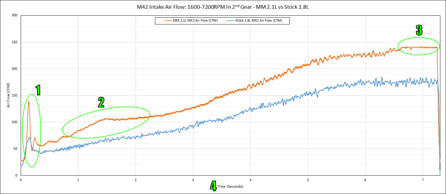
                Of note is this plot. The blue line is a MAF on my stock M42. The orange line is the stock AFM on the 2.1L M42 I had built. So obviously the 2.1L flows a lot more air. But, you will see the thing circled and labeled as Forum That is the resonance I was talking about in the AFM...it is over-reporting air flow there. The blue line does not have that 'bump' since it is reporting accurately (also note...the blue line is HEAVILY filtered by my converter).


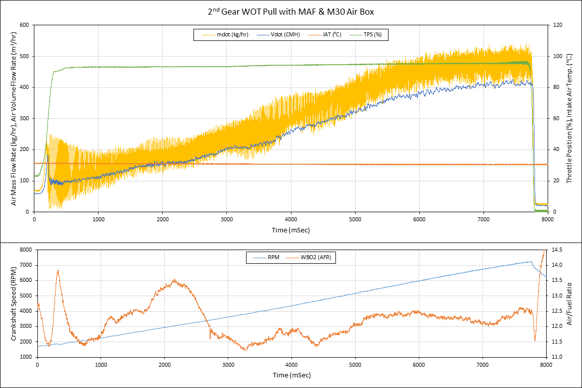
                In this plot, the raw MAF signal is the yellow line and blue is the output of my converter (units converted from kg/hr to m^3/hr).
                Last edited by bmwman91; 06-01-2022, 11:59 AM.

                Transaction Feedback: LINK

                Comment


                  #9
                  Originally posted by dlmrun2002 View Post
                  v
                  That's a good read. I always thought the dual mass flywheel on the M42 was actually helpful on the small revving engine creating some artificial torque. But I never realized the driveline spinning once you are rolling kinda takes over. The M42 would benefit from a lighter flywheel on take off that's for sure. Thanks for the good write up.
                  dlm ny country
                  Oh, the heavy flywheel was there for a reason. It stores a lot more energy, and when you go lightweight you pay a price in terms of idle smoothness, transmission input shaft rattle, and more throttle input to get going. But...worth it!

                  Transaction Feedback: LINK

                  Comment


                    #10
                    Awesome post as always! Thank you very much for sharing your knowledge and past experiences

                    Originally posted by bmwman91 View Post
                    To address the AFM resonance without remapping anything, you would need to take TPS and RPM as additional inputs and modify the transfer function of the converter based on on RPM and TPS. TPS is easy to tap into, but getting RPM is not as simple. You could probably pull the tach signal from the diagnostic plug since there is no need for really high resolution measurement (such as from the crank position sensor, which is a little more tricky to work with). It is a ~12V signal, so you would need to buffer and divide it before hooking up to the Arduino.
                    Have it setup already like you suggested, grabbing the tach output through a voltage divider =D
                    I can log RPM, Wheelspeed, TPS, AFM and IAT at the moment. Then its a matter of selecting the apropriate transfer function based on TPS

                    ...but so far i havent seen the resonance in the way you have.
                    Just maybe i dont have this issue on mine since its so different to the stock intake path
                    In this graph here i went WOT at around 2400. MAF and AFM are following pretty close to the same curve, just slightly offset.
                    At the beginning i show the setup, with a long straight section in front of the MAF to make shure its smooth flow:
                    https://youtu.be/4YD4t1YYOfo">https://youtu.be/4YD4t1YYOfo" type="application/x-shockwave-flash" width="425" height="350">
                    Click image for larger version  Name:	log with MAF and AFM inline.png Views:	0 Size:	303.7 KB ID:	10057302Will do more logs from lower RPM and look for deviations MAF-AFM.
                    Also both sensors reach ~5V. AFM at ~6600 and MAF at ~7100. Doesnt really seem to allign. I would have thought i am closer to a stock one

                    Originally posted by bmwman91 View Post
                    The problem with letting the O2 sensor correct for things is that there are two correction terms that it generates in the ECU. One is the STFT (short term fuel trim) which is an additive factor, and you will see it as an oscillation in the EGO value with a period of 0.5 - 2 seconds depending on operating condition. It is the 'fast' correction. So at PT, yes, lots of stuff can be corrected for pretty quickly up to (IRC) 25% from nominal before tossing a CEL. The other factor is the LTFT (long term fuel trim) which is a multiplicative value, and you can think of it as a correction for the average richness/leanness of operation over ~5 minutes of nominal operation. LTFT is a global term which is applied to all fueling calculations. So if you are running extra rich in PT conditions, the ECU will end up leaning stuff out at WOT where only the LTFT is applied. But, in the case of the M42 AFM resonance thing, it only comes up at PT under fairly limited situations since you have to be at fairly high PT at ~2700RPM to start getting in to the leaned-out parts of those maps. The LTFT would not really be affected much by the MAF swap since the rest of the time things behave linearly(ish).
                    wow...wasnt aware there were LTFTs in an E30, pretty advanced stuff I assumed its just a "goldfish" doing STFTs and not remembering anything

                    100% correct
                    Originally posted by bmwman91 View Post
                    As far as fried pins, it is probably due to the RC filter. The max allowable pin current is 40mA. With a 5V pulsed output through a 100 Ohm resistor, you will see 50mA current transients. The capacitor acts as a short circuit to ground for the higher frequency components of the signal, and is probably why the pins are crapped out. Also, 47uF is HUGE and definitely allowing large transient currents. A 330 or 470 Ohm resistor is a better bet, and you would need to use a smaller cap value. Here is a basic reference on RC filters. Select your values such that the max current to ground is less than 20mA, and your PWM frequency is a minimum of 10X the cutoff frequency, with 100X being better in a single-pole filter like this. So, if PWM frequency is 10kHz, you would ideally want the cutoff to be at 100Hz just as an example.
                    https://www.redcrab-software.com/en/...toff-frequency
                    I had a play here, makes sense why my 2 Pins (~980Hz) i tried with are dead...
                    https://www.falstad.com/circuit/circ...0mRRCAg+cmwWIA
                    Unfortunately the PWM freq of my remaining pins is around 490Hz.
                    From playing with the simulation i thought that with 470 Ohms and 47uF the current should be low enough, will see its already partly dead...

                    Originally posted by bmwman91 View Post
                    Depending on the MAF, you may also start seeing that the output looks very sinusoidal at high throttle openings. The AFM is heavily damped, and the MAF is not, so it will see every intake valve opening when throttle is open a lot. This poses additional problems, but that is a whole other topic. Hopefully you keep playing around with this...it is a great way to learn about basic electrical engineering and signal processing fundamentals.
                    Right now the MAF inputs via a hefty low pass (47k and 1uF) and i think ive not logged fast enough to see that

                    Next step i think is to log faster and with less input filtering to see if i get a similar resonance down low from the AFM and up high from the MAF.
                    Thank you a ton

                    Comment


                      #11
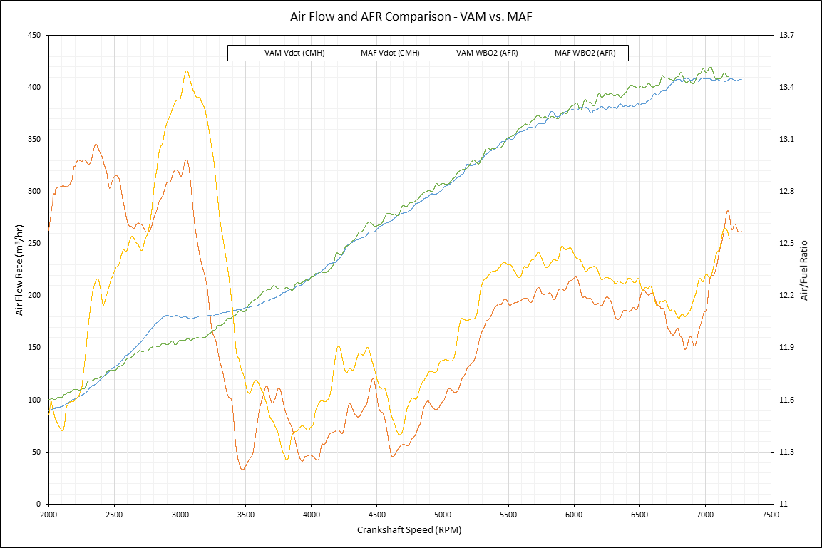
                      This is a better plot showing the AFM resonance vs MAF since it includes RPM and was taken on the same engine (should have bothered to look at the second page of my old thread lol).


                      So the resonance peaks at ~2750RPM and spans 2500~3500RPM. That seems to align with what I see in your scatter plot. There is a fairly obvious bump in the MAF and AFM curves in that range in your data. The reason that the MAF is showing it similarly to the AFM is probably because the AFM value is fluctuating a lot (see the yellow line in the second plot in my previous post). What does the input to your logger's ADC look like (direct connection, RC low-pass, etc?) and what is your ADC sampling rate? My plots were generated with 10kHz ADC sampling rates and 8th order active antialiasing filters.

                      Is your PWM frequency 980Hz, or the pulsewidth update rate? 1kHz is way too low for trying to make a PWM DAC in this application. For sure it is good just to experiment with and learn from, but functionally it'll respond slower than the stock AFM if you have the RC values tuned for a ~10Hz cutoff.

                      The resonance is 100% part of the M42's stock intake and AFM (mostly the AFM). In all of the stock M42 ECU binaries I have been through, they lean-out the fuel maps in the 2500-3500RPM range (WOT, and for high load-axis values in Hi-PT).

                      I don't recommend a 47K resistor on the MAF analog input...this creates a very high impedance input to the ECU's ADC which makes it more susceptible to noise. I understand that you are in the experimentation phase, but for the longer term if you are going to try running the car from the MAF in a permanent way, I suggest reading up on active filters.

                      Keep on experimenting, it sounds like you are figuring stuff out!

                      Transaction Feedback: LINK

                      Comment


                        #12
                        Originally posted by bmwman91 View Post
                        So the resonance peaks at ~2750RPM and spans 2500~3500RPM. That seems to align with what I see in your scatter plot. There is a fairly obvious bump in the MAF and AFM curves in that range in your data. The reason that the MAF is showing it similarly to the AFM is probably because the AFM value is fluctuating a lot (see the yellow line in the second plot in my previous post). What does the input to your logger's ADC look like (direct connection, RC low-pass, etc?) and what is your ADC sampling rate? My plots were generated with 10kHz ADC sampling rates and 8th order active antialiasing filters.
                        I was logging at 10Hz (missing a k right there ) with the MAF directly connected and the AFM was through a low pass (i wonder who came up with that idea )

                        Originally posted by bmwman91 View Post
                        Is your PWM frequency 980Hz, or the pulsewidth update rate? 1kHz is way too low for trying to make a PWM DAC in this application. For sure it is good just to experiment with and learn from, but functionally it'll respond slower than the stock AFM if you have the RC values tuned for a ~10Hz cutoff.
                        To my understanding 490Hz is the actual PWM switching freq on the pins i have left
                        What do you think of using a off the shelf DAC (eg Adafruit) as a better way to output to the ECU?

                        Originally posted by bmwman91 View Post
                        I don't recommend a 47K resistor on the MAF analog input...this creates a very high impedance input to the ECU's ADC which makes it more susceptible to noise. I understand that you are in the experimentation phase, but for the longer term if you are going to try running the car from the MAF in a permanent way, I suggest reading up on active filters.
                        You mean if i use the PWM output through a low pass with R=47k to the ECUs AFM input?

                        Heres a log with a couple of WOT runs where i wanted to replicate the resonance. Its at 20 Hz without any input filtering on AFM and MAF:
                        Click image for larger version

Name:	diagram.png
Views:	598
Size:	219.9 KB
ID:	10057524 To my eye the MAF Value is generally a bit lower everywhere. And 2000-2500 they seem more apart and not very clean at all.

                        For now i try to get a WBO2 mounted so iam not flying blind anymore

                        Comment


                          #13
                          Yeah, a DAC would make life simpler for you. No dealing with a demodulation filter (which is what the RC filter is in that case), faster update rate to the analog value, and probably better output accuracy.

                          Correct, running the PWM output through an RC (demodulation) filter with a R=47K value poses a high impedance source to the ECU's ADC input. That will lead to accuracy problems in the ADC since most of the ones in MCUs have an input capacitor (or array of them) which needs to charge up to the value of the input signal before the value is "read", and a large input impedance means that it may not charge up fully in the allotted time. It also makes that branch of the circuit more susceptible to EMI along the wiring and stuff.

                          I double checked the SAB80C515 datasheet, which is what is used in M1.7, and sure enough it has this to say about input impedance:
                          "For a typical application the value of the impedance should be less than approx. 5 kOhms."

                          It is interesting that there does not appear to be the same "bump" in the signal this time. 20Hz is still pretty slow, but I'd expect to see something there from the AFM. Is it hooked up to the stock air filter box? Also, which MAF are you using? I would expect more oscillation in the output from it at WOT.
                          Last edited by bmwman91; 06-03-2022, 10:06 PM.

                          Transaction Feedback: LINK

                          Comment


                            #14
                            Originally posted by bmwman91 View Post
                            Correct, running the PWM output through an RC (demodulation) filter with a R=47K value poses a high impedance source to the ECU's ADC input. That will lead to accuracy problems in the ADC since most of the ones in MCUs have an input capacitor (or array of them) which needs to charge up to the value of the input signal before the value is "read", and a large input impedance means that it may not charge up fully in the allotted time. It also makes that branch of the circuit more susceptible to EMI along the wiring and stuff.

                            I double checked the SAB80C515 datasheet, which is what is used in M1.7, and sure enough it has this to say about input impedance:
                            "For a typical application the value of the impedance should be less than approx. 5 kOhms."
                            Thank you for taking the time and checking!...this is over my head. I really appreciate you helping me!

                            Originally posted by bmwman91 View Post
                            It is interesting that there does not appear to be the same "bump" in the signal this time. 20Hz is still pretty slow, but I'd expect to see something there from the AFM. Is it hooked up to the stock air filter box? Also, which MAF are you using? I would expect more oscillation in the output from it at WOT.
                            Currently its: open trumpet->MAF->AFM->90° Elbow->Airbox. Here i show it in the beginning how its setup: https://youtu.be/4YD4t1YYOfo
                            The MAF is from a M52B20. 20Hz was the limit where my RPM reading was still reliable. I could try faster with just looking at time vs Airflow.

                            Did some more logging but theres some funky stuff going on
                            This is all data the from the log. At lower RPMs there seems to be a bigger disconnect between the readings. I see to much red where it should be covered by green
                            Click image for larger version

Name:	all data.png
Views:	586
Size:	463.2 KB
ID:	10057628 And this is just the Datapoints where TPS is 100%. The circled MAF Values here dont make sense to me It looks very systematic, there are no points between the "real" curve and these "ghosts". Below 2000 theres no datapoints from the MAF that look realistic at all.
                            Click image for larger version

Name:	just WOT.png
Views:	575
Size:	335.5 KB
ID:	10057629
                            The ghosts are present in the voltage reading directly MAF->Arduino so the math shouldnt be the issue. Maybe ill try with a bit of a lowpass on the MAFs output to the arduino.

                            Comment


                              #15
                              Well, I see that it is a very not-stock M42 lol. I would have said that I don't think that an M42 can be maxing out an M52 MAF, but the US never got the 2.0L variant (only the bigger ones), so I suppose that it is indeed possible if you are making >150bhp.

                              I am also not sure what to make of the 'lines' of data at the bottom of the second chart.

                              Since you are using a very different intake manifold, perhaps it is enough of a change to eliminate / change the AFM resonance behavior. Do you have access to a wide-band O2 sensor? It would be good to log the AFR when you are at WOT. Do you feel like the car sort of loses power at WOT in the 2500-3500 RPM range? Are you on a stock tune?

                              I would be interested to know about the intake that it looks like you are developing...I see 3d printed stuff in there, so fun things must be happening!

                              EDIT: From looking at the comments in the Youtube vid, it sounds like the first plot you showed in the thread was with a stock M42 intake manifold, and the more recent ones are with your prototype? If that is the case, then yeah I would think that the change in AFM resonance is a result of that. Also, as far as the MAF, I found that having a trumpet / velocity stack in front of it helped a fair amount with the output oscillations. You seem to have that taken care of. Can you remove the MAF and put up some pics of the inside so that I can see what the sensor element looks like sitting inside of the overall MAF housing? The fact that the sensor output is as stable as it is makes me think that BMW went with a design that inherently damps the signal.
                              Last edited by bmwman91; 06-04-2022, 09:40 PM.

                              Transaction Feedback: LINK

                              Comment

                              Working...
                              X