

I really don't like relying on the epoxy for the pedal, even though everyone does it. Worst case scenario would be the pedal falling over and getting wedged. On my S54 and now M54, I used the top bolt in the factory location, trimmed pedal bracket tab to fit into the factory sheetmetal chassis tab/pocket thing, then drilled two countersunk M5 holes just forward of the tab on the pedal bracket and bolted those through the floor of the car using aluminum spacers between the plastic pedal bracket and floor of the car. It's pretty solid, but I get that people don't really want to drill holes in the floor of their cars. So to me, there is still no good solution.
If you want a permanent solution for the dipstick tube, I can waterjet a little tab to reach the stud if you give me some dimensions. Obviously it'll need to be welded on to the dipstick, but that's the only way to do it right IMO. Your solution should be fine though
-
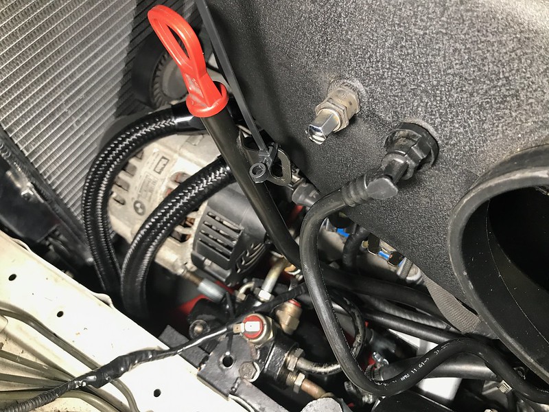
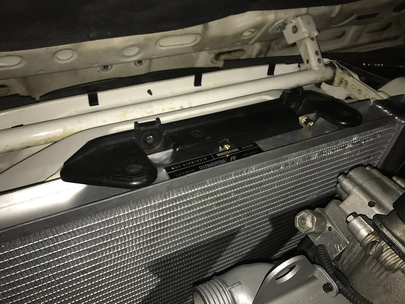
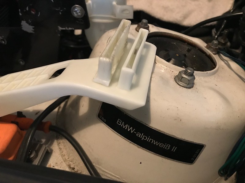
I think it's a known "issue" that with the modified oil pan, the E46 dipstick won't reach it's factory mount stud on the intake manifold. I had picked up some zip-ties that have bolt holes at the end, and they seem like a perfect solution. Maybe not permanent, I haven't decided.
You can see how I put the zip tie on the dipstick tube bracket:
..and how it attaches to the stud/bushing:
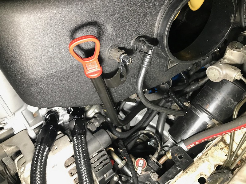
(Don't mind the dirt on that frame rail)
It's not exactly as sturdy as factory, but it braces the tube enough that I can get the dipstick out with one hand so it'll work for now.Last edited by butters; 06-21-2017, 09:05 AM.Leave a comment:
-
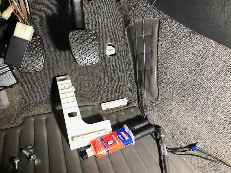
I think I have the pedal mount ready to go, but I'm a little uneasy about relying on the epoxy. If it fails I suppose the worst that can happen is that I lose the ability to apply throttle, which would suck but I don't think it's a safety threat.
I placed the dremel'd clip portion on the top of the chassis tab loosely, then applied epoxy to the top of it and the area of the mount that will bond to it before marrying them in place. While the epoxy was setting up, I threaded in a bolt to the former throttle stop so that the mount was located correctly. I may not snug that up much further, since it will never be loaded in tension. I then gave the new "assembly" a push down onto the chassis tab to where I was happy with its position.
After getting the picture I actually sat in the driver's seat and rested my foot on the mount to allow it to set up for a few minutes before curing for a day or two.Leave a comment:
-
-
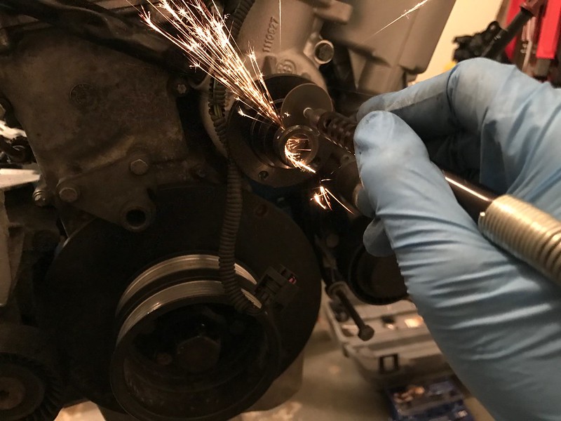
I cut back the threads for the clutch fan, to the point where the shaft becomes solid. I didn't go further because I'm only equipped with a dremel. But in any case, the primary interference is with the hub of the pulley itself. I will check again since you mentioned it though.
Leave a comment:
-
They there butters. You can cut off the water pump nut and gain more room.Leave a comment:
-
Thanks! Yea it's a relief to be over that hump.
Next order of business is the radiator fan. I crossed my fingers hoping my 16" low profile SPAL would fit, but sadly it does not. There's interference at the crank pulley and the hub of the water pump pulley, so I'll have to downsize.
I think I could run two small fans but as I considered it, it also looks like I could offset to the left side of the car and go with a medium profile fan to get as much cfm as the 16" low profile. Granted it will be less surface area, but hopefully the larger rad will offset compared to my experience with the M42 rad.
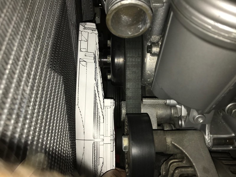
Rather than guess and return the 14" if it's too small, I found drawings of the fans online (a1electronics is the name of the retailer) and printed them off to as close as I could get to 1:1 scale. Ignore the optical illusion, both fans have identical overall thickness and edge thicknesses.
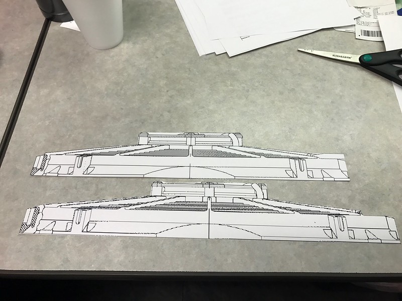
The 14" actually looks like it will work, mounted as low as possible. The hub of the medium profile is about an extra inch, but it's in an area with plenty of room.
So I'll give that a shot.
Maximum clearance is a must here, and I have the usual problem where the E30 radiator bracket doesn't pull the radiator against the core support. So I broke out the dremel and got to work.
I suppose I can cut the foam knobs so they fit back in place for appearances.Leave a comment:
-
Thanks! That's kind of what I'm hoping; there's a lot more information out there on getting the E36 motors to work in the E30.
Last night I did the initial bleeding of the hydraulic system (steering & brake booster) and then pressure-bled the brakes and clutch. No issues there, standard procedure.
I pumped the brake pedal several times for each corner, to help with the bleed of the master cylinder and to exhaust the hydraulic accumulator. This pulls all the fluid from the accumulator for an accurate measure of the system volume via the reservoir.
Final step is to top off the reservoir up to the mesh screen - my guess is that the accumulator will retain a little under half the volume of the reservoir. If these steps aren't followed in order, the reservoir may overflow should the accumulator be drawn upon after engine-off. Lots of info on mye28.com and other online E23 discussions.Leave a comment:
-
Great work! Looks like a huge undertaking. Enjoying reading about the solutions for all of the problems, it will be a huge help to future swappers.Leave a comment:
-
She lives! I wasn't getting power to the ignition harness, turned out to be a bad connection at its power supply connector.
(How the heck do I embed this video?)
What a relief. Still need to bleed coolant, brakes, and power steering, not to mention installing the fan and reassembling the interior.
I started doing the brakes but got no flow out of the right rear caliper, hoping I won't need to bleed the ABS. I could tell that the hydroboost accumulator is still pretty functional, it took something like a dozen pumps before the assist was gone, which is great.Leave a comment:
-
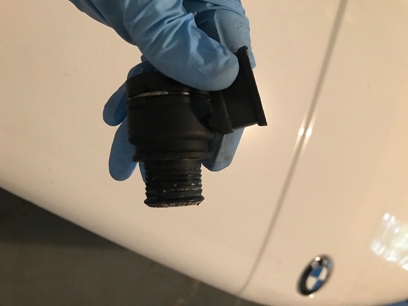
My solution for plumbing the expansion tank is to use the connector from the E46, but swap out the hose. This requires cutting off the clamp, which is just a solid metal band.

Here's what the connector looks like underneath:
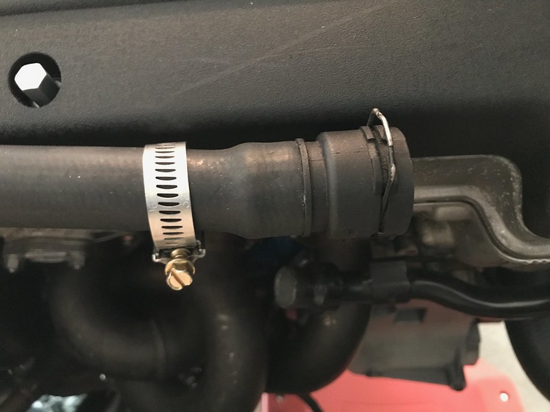
I then cut a 1-inch coolant hose to length and squeezed it on, securing with a hose clamp:
The S54 coolant cap doesn't work with the E30 M3 expansion tank (my mistake for making the assumption) so I have a 1.4-bar E30/E28 M cap on its way to me. Unfortunately it's that old basic metal cap, not a big fan of the look but it was only a few dollars.
My power steering/brakes system is tightened up and filled with DexIII ATF from the dealership. I installed the intake manifold and what I believe to be all the vacuum connections, and at this point it seems I'm not getting spark.
It cranks, and the throttles move, and I'm pretty sure I can smell some faint gas after trying to turn it over, but it won't even try to fire up. I have to check all my electrical connections and break out the multimeter. I tried connecting it to ISTA/Rheingold but the DME wasn't found. I can't draw a conclusion from that yet, it's been a couple months since I used it on my E90.Last edited by butters; 06-08-2017, 06:17 PM.Leave a comment:
-
I finally found a good local hydraulic shop that was willing to work with my old hoses, the trouble is they're only open 8-4:30 M-F so I need to leave work early in order to get there. They modified my pressure hoses for a very reasonable cost, and after going back for an adjustment of the power steering supply hose I think I'm happy with how they all look and install.
For now, the accumulator (bomb) is zip-tied to the former reservoir bracket. The only piece missing is a 1/2" to 3/8" hose union to step up from the rack output to the reservoir, so the 1/2" hose is not in its final spot. Here's how it all looks.... I should really make that booster supply hose all black somehow.

And I made some annotations for clarity, though it still looks a bit messy:
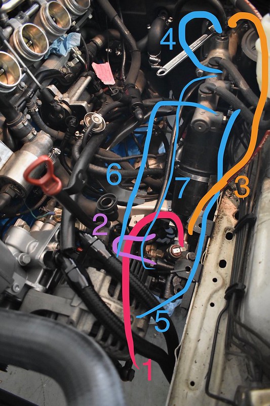
1 - pressure output, pump to accumulator
2 - pressure output, accumulator to rack
3 - pressure output, accumulator to booster
4 - return, booster to reservoir
5 - return, reservoir to pump
6 - return, rack to reservoir (1/2" hose not in final position)
7 - return, accumulator to reservoir
The shop is ordering in that stepped hose union for me, then I can tighten down the fittings, fill it, and install the intake manifold to really get this thing started.Leave a comment:
-
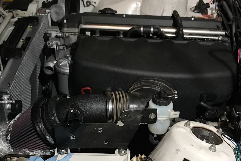
I pulled out the K&N Typhoon intake and assembled it to check the fitment. I'm glad I grabbed the upper portion of the M3 air box because this intake re-uses the air straightening screen and a rubber hose gasket for connecting to the elbow, in addition to the MAF sensor.
Hopefully I'll eventually make some form of a heat shield for this, maybe using the one that is included from K&N. My former cruise bracket is kind of in the way now so I'll get that cut, but I can get it all to sit well enough as-is. I really need to clean the intake elbow.
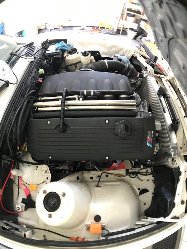
Another perspective, playing with my fisheye (on iPhone 7)
The motor now cranks, but I'm straightening out the fuel supply. Turns out my wiring to the pump was reversed, looking back I'm not sure why I put red to black and vice-versa... so I pulled the pump and re-pinned its connector.
When testing for flow I found that the hoses were also not correct going into the FPR. I was using the logic of "middle hose is supply, bottom is return" but for whatever reason this isn't the case. When in doubt, just follow the hardline from the fuel filter, which is really not difficult to do.
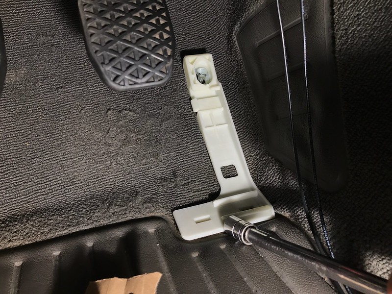
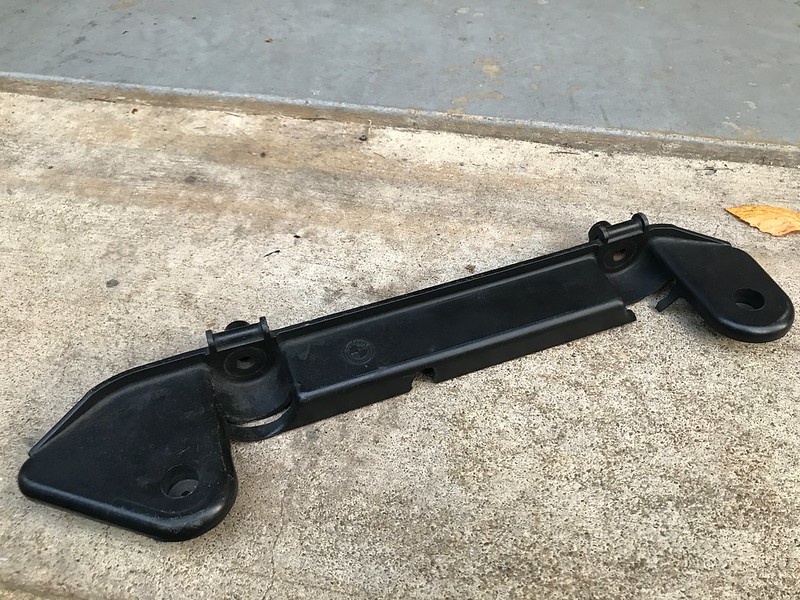
I have a new approach for the pedal bracket mounting problem - rather than moving the base which involves welding, I'm going to move the clip relative to the bracket. My bracket arrived broken - these things are very fragile! - so I removed the clip portion of it using the dremel with cutoff wheel, and my plan is to install it, then epoxy the bracket to it rather than epoxying to the floor.

The arrangement should end up something like this:
Given how fragile these things are I'm not sure I would recommend doing this without buying 2 of the brackets. Theoretically, it could be possible to remove the clip portion and preserve the rest of the bracket, but again, they're really fragile brittle plastic.Last edited by butters; 06-02-2017, 08:46 AM.Leave a comment:


Leave a comment: