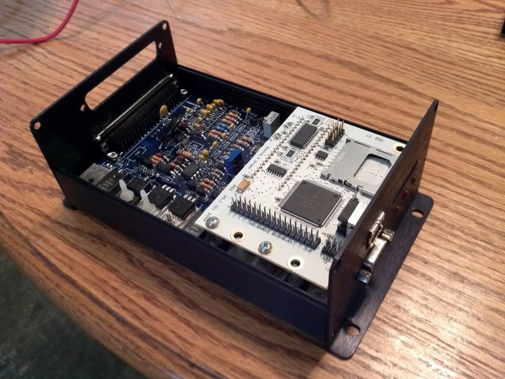
26) Idle valves:
The MS3 card has support for a 4 wire stepper idle valve built-in, just requiring 5 jumpers on the mainboard.
When using the MS3X card in addition it is suggested that you install these jumper wires and use the standard 'FIDLE' components.
If using 2 wire PWM idle without the MS3X card, you will need to upgrade the 'FIDLE' circuit on the V3.0 board. Note, the PWM Idle Valve circuit upgrade can also be used to drive other solenoids such as boost control.
i)Stepper Idle Valve: If using a 4 wired idle valve (or using as two spare outputs) then solder wires from:
a) JS0 to IAC1A
b) JS1 to IAC1B
c) JS2 to IAC2A
d) JS3 to IAC2B
e) Solder components Q4, Q20, R39 and D8 in place. Note, this gives you a programmable output that can drive a relay e.g. cooling fan on FIdle (Pin 30 of the db37)
ii) PWM Idle Valve:
Note! This is not required with the MS3X card - use one of the mid-current outputs on the MS3X card for you idle valve and fit the standard components Q4, Q20, R39, D8.
2, 3 wired devices need a TIP122 (not supplied in kit) and mica insulation.
a) Cut the legs of the TIP122 so they are half the length they were as new.
b) Fit a piece of mica insulation under it and using plastic screws bolt it to the case or a space on the heatsink. Don't forget the mica.
c) Solder a wire from the centre pin of Q4 to the left side of the TIP122.
d) Solder a wire from the bottom pin of Q4 to the middle pin of the TIP122
e) Get an IN4001 (you should have a spare from D2) and solder the stripped end of it into s12, this is below the TIP122 on the main board.
Push it all the way in so the body sticks up in the air against the board.
f) Solder a wire from the non-banded side of the diode to the centre pin of the TIP122.
e) Solder a lead onto the copper wire that’s in position R43 to the right sided pin of the TIP122. (Ground for the TIP122 Idle driver)
iii) No Idle Valve:
a) Solder components Q4, Q20, R39 and D8 in place. Note, this gives you a programmable output that can drive a relay e.g. cooling fan relay on FIdle (Pin 30 of the db37)


Leave a comment: