
I was also thinking a thermal adhesive, I've used Arctic Silver adhesive in the past, but it'd have to be the type they make that's non-conductive, I think it's called Ceramique.
edit: no the non-conductive adhesive is actually the Arctic Alumina.
-
Also, I've got a pinout for the stock DME now, finally found it in my Bentley, I think I'm going to try to fashion a harness similar to hoveringuy's Motronic harness.Leave a comment:
-
they make thermal heatsink tape just for this, try a computer/modding site.
they are soldered on, you'll have to unsolder them..
personally I'd just buy a set of BIP's and be done with it. :pLeave a comment:
-
The middle pin that's unused and the backing metal connector have almost no resistance, I'm guessing the middle pin can be used as the coil out as well... How would I mount these to a heatsink when the coil out is the metal backing plate and there's no screw holes like on the ones inside the Megasquirt?
I can't even figure out how to get them OFF of the board I guess I need to find some sort of heat gun.
Leave a comment:
-
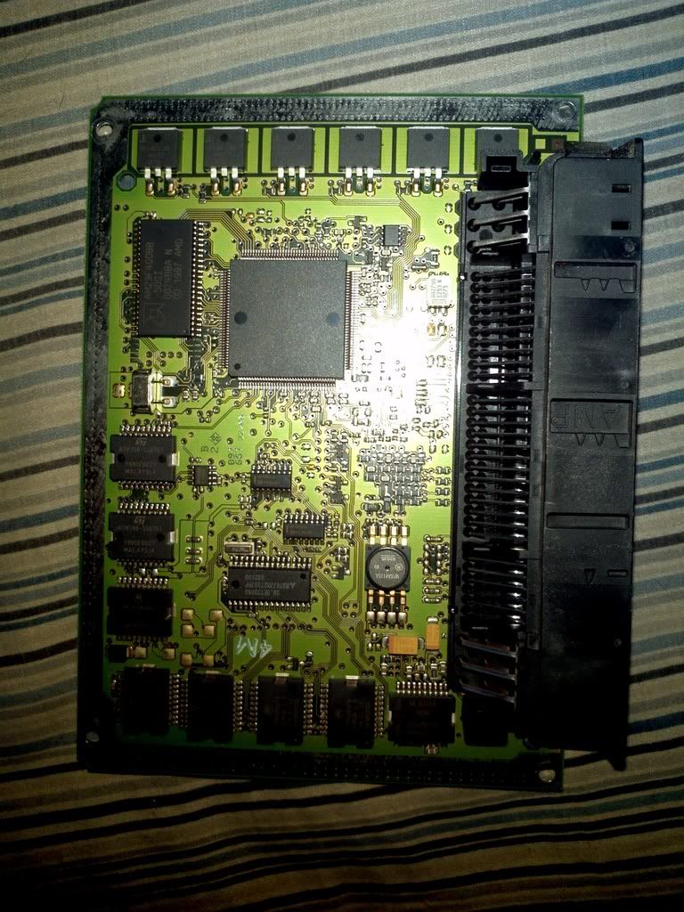
generally yes you want them heatsinked. I think the stock ECU uses the part that the back solders onto as it's heat sink.Leave a comment:
-
Here's what I got measuring resistance with corresponding pins:
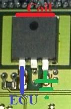
3rd terminal went to ground pin(pin 5), the back plate terminal went to the individual coil output pins and I'm assuming the other pin is the signal from the ECU. Does this sound feasable? And would these drivers need a backing plate of some sort for heat absorption? Doesn't seem like the stock DME has much of that...Leave a comment:
-
Will do. Appreciate all the hand holding
My sister still lives up in Washington, so if/when I'm ever up in the area I'll be sure to buy you a beer or something :pLeave a comment:
-
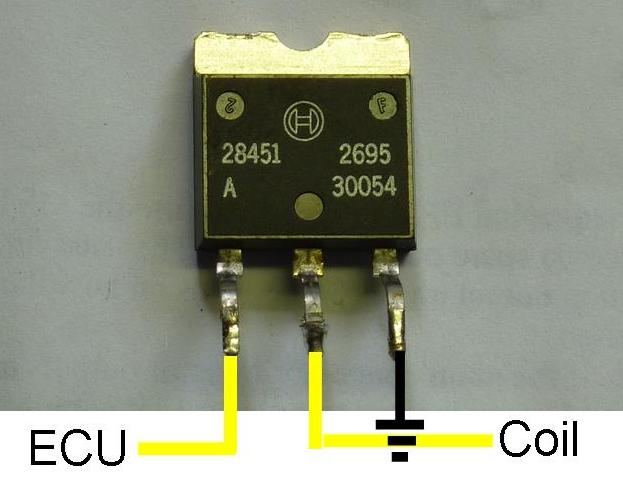
Those would work fine. Those boards have 4 layers, the middle two layers are usually power and ground so you can't see where they are grounded together. With a multimeter see which pins have continuity with each other and ground. See which pins (left, middle or right) have continuity with pins on the connector. Those are your outputs.Leave a comment:
-
-
-
-
you need drivers for sequential spark.. you don't need to do anything extra to do sequential fuel. just hook the injector wires to the MS3x injector outputs.Leave a comment:
-
So gurov is using a Toyota igniter box to run the coils, as seen here:

Can get them for around $20 on ebay but they don't have the harness... I'm thinking perhaps I hit the local junkyards and find one with harness, I'm sure the junkyards will have that year Camry.
Alternatively, this was mentioned in your blog:
What's the best way to get these? Are they just pulled from parts ECU's?
And am I right that, to run sequential injection, you'd need 6 of these, 1 per coil, mounted on some kind of metal material for heat transfer?Leave a comment:
-
I started a blog. Look at me, I'm blogging!
Follow my M54 Megasquirt conversion.
Leave a comment:
-
ah, yes. That part was confusing. I think you might be right, the board probably has them already. matt at diy would be a good person to confirm that with.Leave a comment:

Leave a comment: