
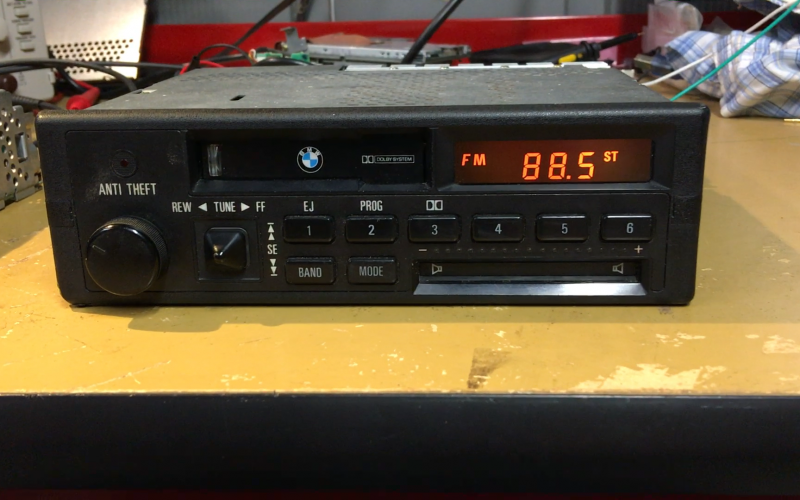
Anyone know how to fix the slider on the CM5908? Mine seems to have developed a mind of its own recently. When touching the presets 3-6 above it it usually adjusts the Bass down, but sometimes up. I try to fix it with my finger but it doesn't respond, but I hold the Mode and it will reset to middle. I also tried blowing it out with some compressed air but no change.
-
-
sliders themselves wear out. they work the same as a potentiometer. there is a compressed air and alcohol based cleaner that you can use to clean them, but if they are simply worn it won't fix it. i've replaced them on audio and lighting boards before, perhaps there is a specialist that can repair it if it's worn out in yours. -
So I found this awesome site where someone figures out how the IR slider works. I still need to see if I can understand it. It does not seem like a normal potentiometer.
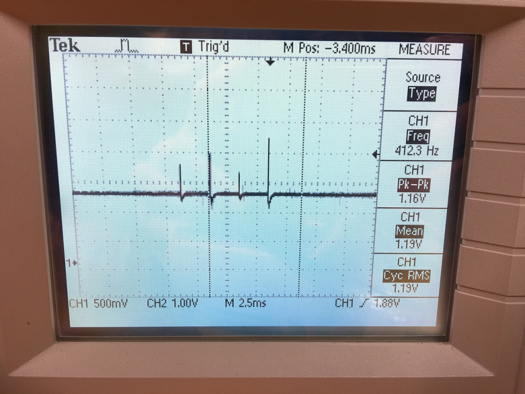
Some pictures of mine disassembled:Last was figuring out the IR slider. I had no idea what to expect here, but had a hunch it might be analog in the way it’s signaled. I got out the scope, started probing on the connector, and eventually saw this. Bingo! 4 pulses sent every ~20 ms, each corresponding to one of four IR sensors in the slider. When a finger occludes one of the sensors, its output voltage will go to zero. So its time-multiplexing 4 analog sensors onto one line. After that, the trick was to figure out how I’d be able to capture those samples.
The Arduino has ADCs, but I needed a way to sample the peak on these very short spikes. I ended up using an analog peak-detector circuit shown below which simply holds the peak input voltage (see here for more info). A transistor is used to reset the detector by draining the cap holding the peak voltage. A comparator is used to trigger an interrupt to the Arduino any time the voltage falls below a voltage threshold just slightly above the bias voltage. That way, every time we fall from a pulse peak, the Arduino is triggered, samples the held voltage, then drains it. This works like a charm!
So I think it uses the 2 clear LEDs (probably IR) send the signal, and then the plastic housing filters it so it shines down on the 4 sensors in the bottom (under the "RED" on the PCB). Then like the above site said when you block the signal to the sensor it does some processing to see which way you are adjusting.
I tried with my phone camera but not seeing any IR, but tested on a TV remote and you can see it.
Also testing with the radio it does not register anything when its disassembled. Looks like the way the plastic blocks the light so it only works with the front cover and faceplate assembled.
Still need to do more testing to see if I can figure out anything. I don't have a fancy oscilloscope (or know how to use one) and my multimeter probes are a bit too chunky for these small pads.Last edited by amarino; 08-15-2023, 10:38 AM.Comment
-
Maybe, one of the infrared phototransistors at the bottom is dead.
Comment
-
that would certainly correlate with the described skipping behavior. Also not all that difficult to verify.
amarino reach out via bradnic@oemhifi.com and I'll get you a replacement IR assembly from my parts bin.I BUY/SELL REFURBISHED CM5907s & CM5908s
HOWTOs:
DB vert plastic bumpers
OEM Keys
MTech1 docs
88 ix Lach/Card
91 ic Calypso 3.1
86 Cosmo 2.7
OEM+ or bust!

reelizmpro: I will always be an e30 guy.. I still do all of my own labor
TrentW: There's just something so right about a well-built M20 in an E30
e30m3s54turbo: I save my money for tuner parts.Comment
-
Thank you for the offer. Email sent.
I'm still trying to troubleshoot mine and have some thinner multimeter probes on order from Amazon. It's hard to get back there with everything installed to measure any voltage / etc. And I don't want to go the route of fully disassembling as the mainboard is soldered to the metal case.
It would be great to have a working unit from your stash and I can poke around at mine more.
Using cardboard so it doesn't short out on the metal case, then bending the PCB to try and get at the IR receiver contacts. Can't get any more clearance with the flat cable installed. Hopefully with these multimeter test probes I can get it at from the topside: https://www.amazon.com/gp/product/B08W2QZ9S4/Comment
-
Thank you bradnic for that extra board. I've been poking around at both my original and that one but can't find anything different. I traced the IR receivers and found out they don't use the main ribbon cable, but the separate 5 pin harness on the top left next to the volume rocker, KS0-3 and GND.
I've tried with my older Fluke multimeter but haven't been able to get any pattern testing resistance, continuity, voltage dc or ac when powered on or off. I've tried testing by covering the sensor with my finger while also probing both ends. Probably going to table this for now as it seems like I need some oscilloscope and better circuit tracing skills to see where it goes beyond the plug on the mainboard. This is all a bit beyond my skills for now but hopefully this helps someone else who knows what they're doing and can pick up from here.
Comment

Comment