-
1988 E30 ALPINA B3 2.7 #224/257 Made in Buchloe

see more : http://www.r3vlimited.com/board/showthread.php?t=71686&referrerid=12460 -
1988 E30 ALPINA B3 2.7 #224/257 Made in Buchloe
see more : http://www.r3vlimited.com/board/showthread.php?t=71686&referrerid=12460Comment
-
Today's update:
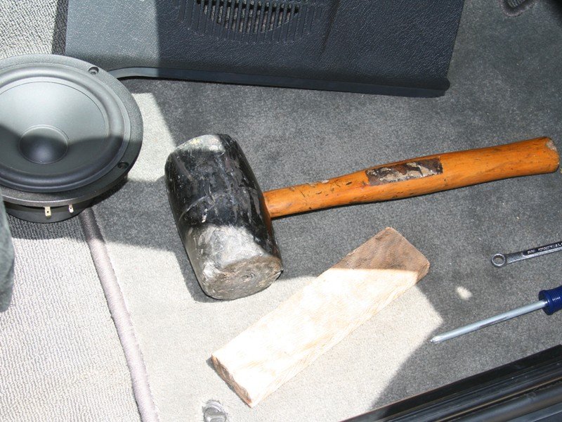
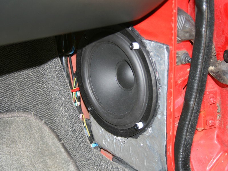
I got the front woofers installed. This was a real bitch. The speaker pods are part of the door jamb, so you really cannot pound the metal out much unless you don't plan to open your door all the way. I plan to open it all the way, so I pounded it out as much as I could without interfering with anything. This bought a few millimeters.
My favorite tool!
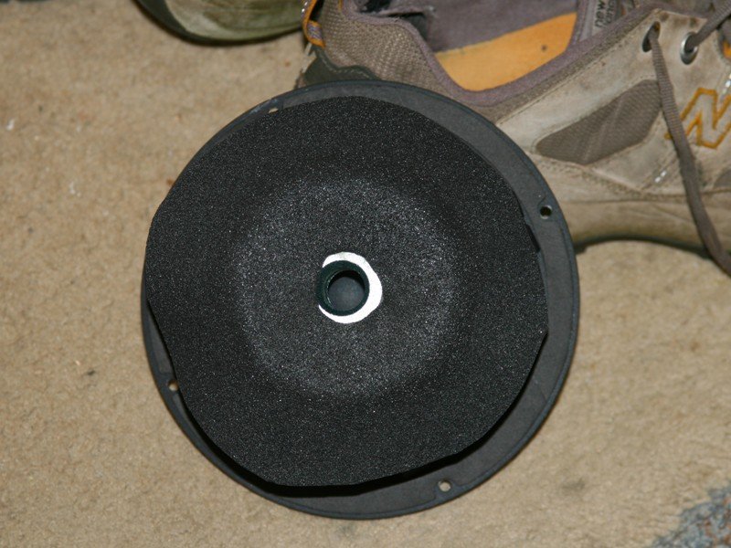
The rear of the pole piece does contact the back of the pod when installed. To avoid buzzing and scraping problems, I put some 1/8" closed cell foam on the back of the drivers. They don't sit completely flat in the back, so the pole piece vent is not blocked off. The foam piece is glued on so it won't go "walking."
Since the surface that they mate to was pulled out a little, and the woofers are reasonably thick, the kick panel cover needs to be spaced out so as not to rest on the cloth surround. I turned out some screw spacers on my trusty lathe from some Delrin bar stock. The cover sits on the screw heads now, and there is Damplifier/foam on the back of it so there is no buzzing. I still need to fasten the front of it (up in the footwell) so that it does not stick out so far into the foot area. I only had to make a minor cut to an edge on the glove box so that it won't scrape on the cover. It is totally out of sight, which is nice.
The driver's side took a bit more work. I chopped off the portion of the kick panel cover that goes under the hood release latch since that wasn't going to fit anymore. I also had to make a small cut-out in the knee bolster cover, which is conveniently out-of-sight. The hood release latch needed to be spaced out to accommodate the new position of the cover, so I made some 10mm Delrin spacers and it works like a fucking charm! I was sweating the installation at first, wondering if I might have to use different drivers, but the BFH (big f*****g hammer) & some fearless chopping got the job done. I will seal their perimeters completely when I run the new signal lines.
Thankfully, that was probably the last of the super tricky stuff. I will be working on the sub baffle & electronic hardware mounting next. I opted to use some cabinet-grade Baltic Birch plywood over MDF for this. Plywood does a lot better with heat & moisture in the long run, and since I am not building an enclosure I don't really need to worry about wall resonance.Last edited by bmwman91; 05-30-2010, 09:38 AM.Comment
-
Wish I could hear this when completed... very nice work.
I've always wanted to go with an active setup, but never had the drive (or cash) to really dive in. Now you've got me looking at the audiocontrol stuff again."A good memory for quotes combined with a poor memory for attribution can lead to a false sense of originality."
-----------------------------------------
91 318is Turbo Sold
87 325 Daily driver Sold
06 4.8is X5
06 Mtec X3
05 4.4i X5 Sold
92 325ic Sold & Re-purchased
90 325i Sold
97 328is Sold
01 323ci Sold
92 325i Sold
83 528e Totaled
98 328i Sold
93 325i SoldComment
-
Time for an update:
I have spent a good few days reverse-engineering the amplifier's input stages. My main reason for this is bypassing the active filtering on channel 5 since the amp was designed without a bypass for it. CH5 uses a class-D power stage, and this one was only designed to do lower frequency stuff. Since I will be using a higher-order, nicer, external crossover before CH5, I feel that I can safely bypass it. The external cutoff frequency isn't too much higher than the limit on the amp's dial anyway.
I have succeeded in bypassing this and basically jumped the output of the gain-setting op-amp to the input of the final output buffer / RF filter. With 12V powering the amplifier, CH5 is close to clipping with the minimum gain setting and the expected maximum input level from the 6XS. I am going to change out one or two resistors to allow the gain to be adjusted lower than it otherwise would be in the input stage.
The other order of business will be to install some nicer op-amps. The unit currently uses some STMicro MC4558 units, which are OK for hobby type stuff, but are not really great for audio. Since the power stages probably aren't world-class or anything, I am not going to go dropping serious coin on ridiculous op-amps that headphone enthusiasts like, but I will put in ones with lower noise figures & such. I have ordered some OPA2134's to put in (same pin-outs). They are a good balance of performance and price. You also would not want to put in op-amps with >10MHz bandwidth because there is a lot of high-speed switching circuitry generating RF EMI in there, and you don't want that amplified.
What is the typical battery voltage in an E30 with a good battery when the car is not running? The power rails vary in voltage depending on the input (+/- 23V for Ch1-4 & +/- 41.4V for CH5 with 12V in, +/- 27.3V for Ch1-4 & +/- 48.4V for 14V input). As such, I want to set the gains to be just on the verge of clipping with the lowest reasonable battery voltage present in case I crank it up with the engine off. I am not after absolute maximum power or anything like that...just maximum power under worst-case conditions.
Oh yeah, and once I get the gains dialed in I am removing the potentiometers & putting in regular resistors in their place (of the right value). Cheap pots tend not to hold their setting, especially in an environment like a car, and more-so when mounted near a sub! That, and the dual-pots in there aren't very symmetric, so the gains between CH1/2 & CH3/4 differ a bit for a given position on the pot. Resistors will take care of that.Comment
-
wow... Take pics of your amp mods. This is crazy and I would love to see what it all looks liek complete.e30sport.net
'86 325es - s54b32tu - 6-speed - Mtech 1
'89 325is - m20b25 - 5-speed - Individual
'06 M3 Competition - 6-speed
'19 Porsche GT3 RS - 7-speed PDK
'94 Lancia Delta HF Integrale EvoII - Giallo Ginestra
'97 Range Rover VitesseComment
-
This is getting a bit technical for the peeps who like picture books.Comment
-

Closing SOON!"LAST CHANCE FOR G.A.S." DEAL IS ON NOW
Luke AT germanaudiospecialties DOT com or text 425-761-6450, or for quickest answers, call me at the shop 360-669-0398
Thanks for 10 years of fun!Comment
-
Maybe. Can you take some pictures of the guts? It was a long, painstaking process involving a beeping multimeter (4 layer PCBs are a pain!).
I am certainly willing to give it a shot as long as you aren't in a giant hurry or anything. There will be some sort of "nominal" fee for this service ;).Comment
-
Alrighty, I got the opamps today. I will install them in the lab at work tomorrow at lunch lol.
I also returned that circle-cutter jig and bought a Router Buddy instead. It looks like it will be a very useful little tool!
Oh, and baltic birch plywood burns like a bitch when cutting with a router. Freaking annoying, I wrecked a bit a couple days ago. MDF was easier to work with than this stuff, which is sort of surprising.Comment
-
Hey man I checked out the sub box you built...very nice. What do you do as a mechanical engineer? I finally decided to go back to college and finish up my degree in mechanical engineering. Have you posted up a design for your sub box yet?Comment
-
Thanks. The build was a real adventure. It was tons of fun though. I haven't posted up any plans or anything. It was a custom design I came up with & never really made formal drawings or anything. The size, cost & weight of it sort of make it unlikely that anyone else will want to build it, except audio nuts who probably know enough to design their own. At 24"x24"x30", 130lbs and ~$500 in raw materials & a couple specialty tools, it's not going to be super popular lol. If you don't already have the $1500-3000 in basic woodworking tools it takes and a garage...you get the idea lol.
With that said, if there was moderate interest, I would publish detailed drawings. The basics are that it has 156L of actual internal volume (with bracing, the driver & the port accounted for) and the port is tuned to 18Hz. This thing will actually go plenty low without the port as well. I have played with plugging it.
I work as a hardware engineer in consumer electronics presently. I mainly deal with testing & instrumentation, and am slowly working on a masters in EE focusing on controls & mixed-signal systems.Comment
-
"A good memory for quotes combined with a poor memory for attribution can lead to a false sense of originality."
-----------------------------------------
91 318is Turbo Sold
87 325 Daily driver Sold
06 4.8is X5
06 Mtec X3
05 4.4i X5 Sold
92 325ic Sold & Re-purchased
90 325i Sold
97 328is Sold
01 323ci Sold
92 325i Sold
83 528e Totaled
98 328i Sold
93 325i SoldComment
-
Might as well post it upComment


Comment