
So, there is a bit of info out there regarding tooth angles and whatnot for the M42, but no single cohesive place with all of it. If you read around enough, you will probably come to the conclusion that the first tooth pulse after the gap is 114 degrees BTDC, which is correct as far as the physical setup on the engine goes. Since I am planning to rock a MS3Pro ECU at some point in the next year or two, I wanted to get a clear idea about this and document it once and for all. I borrowed an oscilloscope and popped the shell apart on the 88 pin connector that plugs into the Motronic so I could directly measure the VR sensors (and yes, both are VR type). It's been too long that only the M20 guys have had nice, well defined information to work from, and it is time for the M42 to get some nerd-love!
Which wire is which? This causes some confusion, mainly because the cam and crank sensors have the same wire colors, but one's polarity is reversed because BMW decided to swap the wires (for whatever reason). Keep in mind that this is the E30 M42, and I do not know if this changed in the E36.
- The crank sensor uses pins 67 and 68 of the Motronic. Pin 67 takes the black wire from the crank sensor, and this is the POSITIVE sensor output. Pin 68 takes the yellow wire from the crank sensor, and this connection is GROUNDED inside the Motronic. So, pin 67 is the crank sensor signal, which by convention would be called the positive output of the sensor.
- The cam sensor uses pins 16 and 44 of the Motronic. Pin 16 takes the yellow wire from the cam sensor, and this is the NEGATIVE sensor output. Pin 44 takes the black wire from the cam sensor, and this connection is GROUNDED inside the Motronic. So, pin 16 is the cam sensor signal, which by convention would be called the negative output of the sensor.
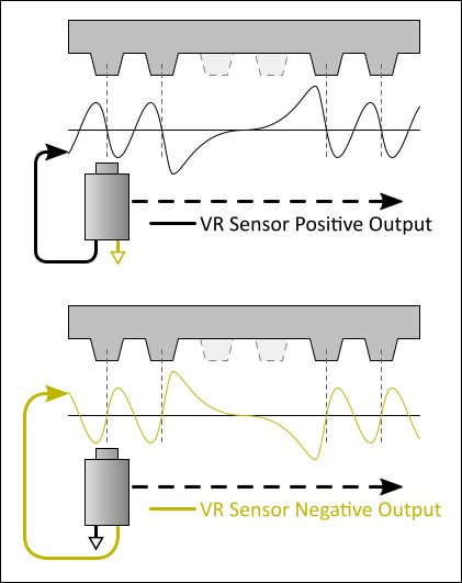
I am not sure why BMW reversed the signal wires between the two sensors. For those that are going stand-alone, you have the option of getting your cam signal from pin 44 (the positive output) and then whatever conditioner circuit you are feeding that (and the crank signal) into will behave the same way. With a VR sensor, both wires will essentially provide the same signal, but one is "flipped upside-down" relative to the other. Most VR conditioner circuits are designed for the VR positive output, and will give a digital rising edge when the VR output crosses zero from positive to negative.
The positive/negative convention is shown in the diagram below.
Great, so that is a lot of reading about VR basics. What about the M42?
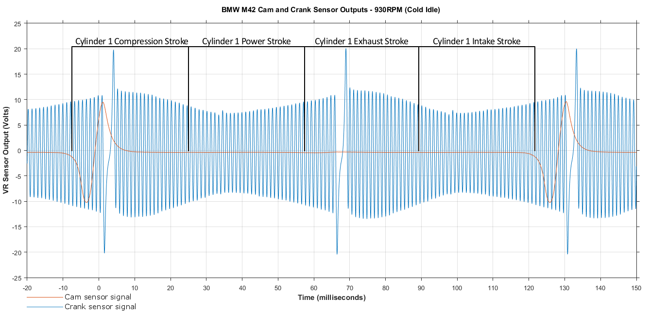
First, here's a scope shot of two full rotations of the crankshaft, with some annotations added. The amplitude changes a lot as the crank turns because my damper wheel is either out-of-round, or just worn out, so some teeth get closer to the sensor than those on the other side of the wheel. I did some measurements at 2000RPM and 3500RPM as well, and at 3500RPM the big voltage spike peaked at around 50V. That means that at redline, the VR sensor is going to be putting out a signal that peaks at over 100V.
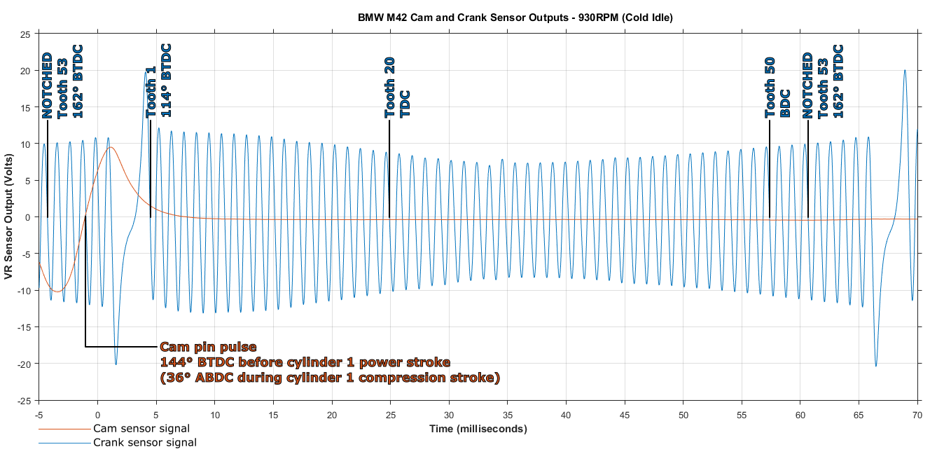
Here it is zoomed in a bit, with the important teeth marked.
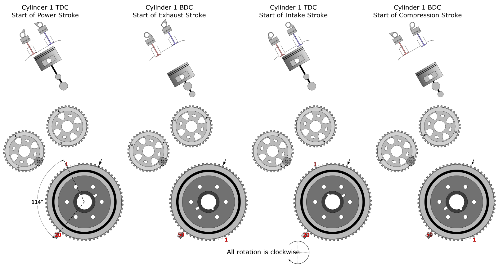
And here's a fun little graphic showing what is what and the relationship between moving parts with respect to the cam and crank sensors. Note that the cam lobes are not to scale or anything; they are just for fun to illustrate the general idea.
Note:
This is all based on photos of mine from over the years and a lot of online image searching. Thankfully it all seems to agree with existing information, as well as the oscilloscope measurements. If you find an error or think that you see an error, please let me know so that I can see if a correction is needed.
I plan to do a pretty in-depth look at ignition coil dwell times too, since that is also a critical parameter. That will involve more oscilloscope action with the goal of determining the factory dwell times for the coils (both for the M42 coils, and the M54 coils that many of us run with our COP conversion). In a year or two (or whenever I get my ass into gear and install an aftermarket ECU) I will try to document all of the factory equipment (thermistors, idle control valve, etc) so that others will not have to spend weeks and weeks scratching their heads.
Which wire is which? This causes some confusion, mainly because the cam and crank sensors have the same wire colors, but one's polarity is reversed because BMW decided to swap the wires (for whatever reason). Keep in mind that this is the E30 M42, and I do not know if this changed in the E36.
- The crank sensor uses pins 67 and 68 of the Motronic. Pin 67 takes the black wire from the crank sensor, and this is the POSITIVE sensor output. Pin 68 takes the yellow wire from the crank sensor, and this connection is GROUNDED inside the Motronic. So, pin 67 is the crank sensor signal, which by convention would be called the positive output of the sensor.
- The cam sensor uses pins 16 and 44 of the Motronic. Pin 16 takes the yellow wire from the cam sensor, and this is the NEGATIVE sensor output. Pin 44 takes the black wire from the cam sensor, and this connection is GROUNDED inside the Motronic. So, pin 16 is the cam sensor signal, which by convention would be called the negative output of the sensor.
I am not sure why BMW reversed the signal wires between the two sensors. For those that are going stand-alone, you have the option of getting your cam signal from pin 44 (the positive output) and then whatever conditioner circuit you are feeding that (and the crank signal) into will behave the same way. With a VR sensor, both wires will essentially provide the same signal, but one is "flipped upside-down" relative to the other. Most VR conditioner circuits are designed for the VR positive output, and will give a digital rising edge when the VR output crosses zero from positive to negative.
The positive/negative convention is shown in the diagram below.
Great, so that is a lot of reading about VR basics. What about the M42?
First, here's a scope shot of two full rotations of the crankshaft, with some annotations added. The amplitude changes a lot as the crank turns because my damper wheel is either out-of-round, or just worn out, so some teeth get closer to the sensor than those on the other side of the wheel. I did some measurements at 2000RPM and 3500RPM as well, and at 3500RPM the big voltage spike peaked at around 50V. That means that at redline, the VR sensor is going to be putting out a signal that peaks at over 100V.
Here it is zoomed in a bit, with the important teeth marked.
And here's a fun little graphic showing what is what and the relationship between moving parts with respect to the cam and crank sensors. Note that the cam lobes are not to scale or anything; they are just for fun to illustrate the general idea.
Note:
This is all based on photos of mine from over the years and a lot of online image searching. Thankfully it all seems to agree with existing information, as well as the oscilloscope measurements. If you find an error or think that you see an error, please let me know so that I can see if a correction is needed.
I plan to do a pretty in-depth look at ignition coil dwell times too, since that is also a critical parameter. That will involve more oscilloscope action with the goal of determining the factory dwell times for the coils (both for the M42 coils, and the M54 coils that many of us run with our COP conversion). In a year or two (or whenever I get my ass into gear and install an aftermarket ECU) I will try to document all of the factory equipment (thermistors, idle control valve, etc) so that others will not have to spend weeks and weeks scratching their heads.


Comment