Announcement

Collapse
No announcement yet.

M42 ECU Conversion: Link G4X / E36X

Collapse
X
 
  • Filter
  • Time
  • Show
Clear All
new posts

    #31
    Originally posted by wazzu70 View Post
    Cool work on the wheel speed input. I wish I had experience with circuitry! I just dive in when something is not working like I expect and try to learn why.

    Im familiar with the PD engines. They have a “unit injector” which was a precursor to the common rail system to boost injection pressures. Like most engine changes, the purpose is to meet more stringent emission regulations!
    If you want a 4CH VR-to-TTL board for your VEMS, let me know. PCB orders have a minimum quantity of 5 anyway...

    The PD injection setup is interesting. Definitely a half-way point between the remote mechanical pump and current common-rail. Lord knows that the unit injectors are expensive as hell (although the CR injectors are even worse), and part of me wants to sell the TDI now while it is running well still. Replacing all of them would cost me almost as much as the car itself did. If I do go with another TDI, it will probably be a "dieselgate" CR one. A friend got a crazy good deal on a 2016 Passat 6MT that he bought in Utah and drove back to CA. It routinely gets 45 MPG, which is impressive given its size and weight.

    Transaction Feedback: LINK

    Comment


      #32
      Originally posted by bmwman91 View Post

      Hmmm. I know that the toothed wheel in the diff has 9 teeth per revolution. It had always been my assumption that the cluster duplicated or passed-through that signal, but you are saying that your measurements indicate 2.4 pulses per revolution? That's garbage lol. I am definitely going to be developing a 4-channel VR-to-TTL module, and I can assemble some spares that I can make available at a very fair price. It'll be a little board in a 3D printed enclosure that nests nicely above the knee bolster thing, next to the ABS computer.
      Yes, definitely garbage. I have attached my wheel speed setup for reference, it is definitely coming out at a 2.41 ticks/rotation effective ratio. Again, this isn't the actual diff signal, it is the speed out pulse that normally goes to the cruise module.

      Click image for larger version

Name:	WheelSpeedSetup.PNG
Views:	267
Size:	66.5 KB
ID:	9966305

      If you are going ahead with the wheel sensor boards I would probably be interested. If not I have a few backup plans I can put in place, so no worries.

      Comment


        #33
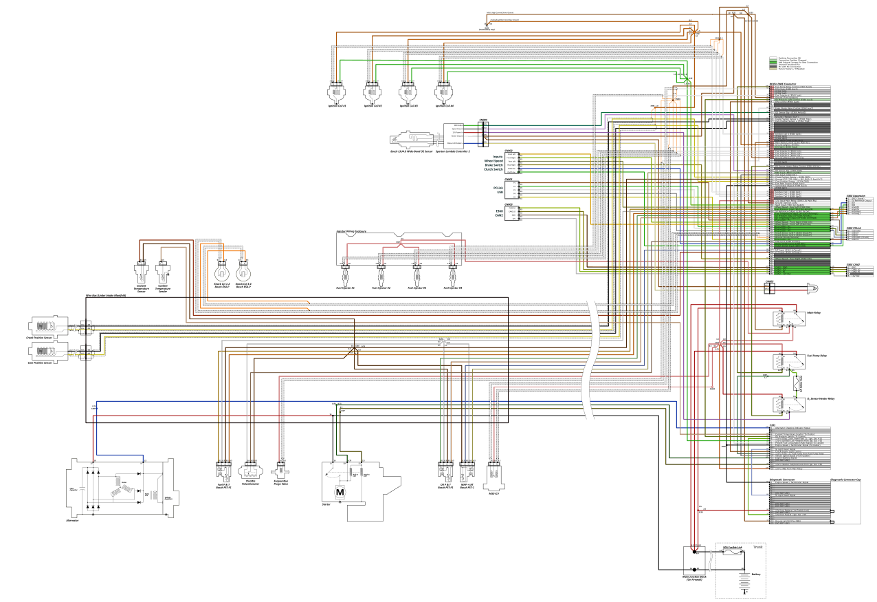
        I have been been a little quiet in here lately, but I have been working on this more. Specifically, I have been drawing up the fully detailed wiring diagram for the new harness and a pin-board to get length estimates with. Although I do not plan to make a physical pin-board since enough of the original harness will remain intact to keep things properly sized, I will probably install it into the chassis after removing all of the tape and cleaning it so that I can route all of the new stuff in-place to get the lengths exactly right. The pin-board drawing is more for determining quantities of wire to buy.

        PDF links are the full-size drawings of the "thumbnail" images.

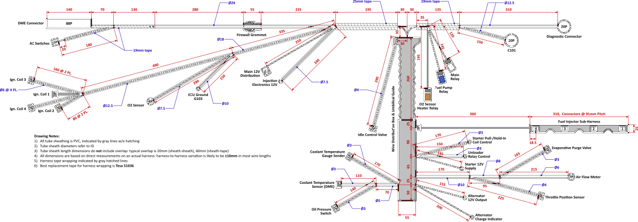
        For the pin-board drawing, I started out by measuring out everything on a 100% stock harness. Dimensions probably vary a bit since these things are all 30 years old and varying amounts of tugging/abuse have been applied, but everything is likely within 1cm of where it should be.


        OEM E30 M42 Harness Dimensions


        I have already posted this elsewhere, but here are the OEM E30 M42 wiring diagram and the modified one I am using currently with my MAF conversion & WBO2 on stock Motronic, in full color:
        http://www.e30tuner.com/assist/m42wi..._318iS_OEM.pdf
        http://www.e30tuner.com/assist/m42wi...ess_MM2100.pdf


        Anyway, it took a fair bit of work to figure out exactly how I wanted to add & route all of the new stuff for the Link ECU. A primary goal was to have a single wire loom coming from the ECU, which means that I will need to void my warranty and solder some jumper wires inside the thing from the "extra" I/O pins on the G4X ECU and unused pins on the main 88 pin connector. Also, while it has a built-in MAP sensor, I do not want to have a vacuum line running through the firewall (both from a SMOG/visual standpoint, and just for cleanliness). So that means that I will be using a Bosch MAP+IAT sensor, mounted directly in the plenum of the intake manifold.

        The other thing I had to think about a lot was the fuel injector wiring. The stock setup has a pluggable sub-harness for the injectors. The ONLY reason I can see for this is to make engine removal/installation simpler at the factory. Removing the injector harness requires removal of the upper intake manifold. In my experience, the M42 is much more easily removed/installed without the upper manifold anyway, and (*FINGERS CROSSED*) I don't anticipate removing the engine again anytime soon. With the "mess under the intake" mod, the upper manifold can be removed without messing with the TB, and is a 10 minute job. So, with that said, the fuel injector wiring will run through the little side-port in the rubber umbilical that the ICV wires previously exited from. This is the most direct route for the injectors. The ICV, MAP & fuel P&T sensor wiring will exit where the fuel injector connector used to be (with a 3D printed PEEK filler/adapter for the grommet). It just makes more sense that way.

        New stuff which I will be routing through the wire box under the intake manifold:
        - Oil pressure + temperature (mounted in oil filter housing where the pressure switch was, with some custom machining to adapt the existing M12x1.5 hole to take the M10x1 sensor)
        - Fuel pressure + temperature (will machine an inline tee adapter for the fuel feed line)
        - Manifold pressure + temperature (no long vacuum lines to mess with, and nice direct measurements in the plenum)
        - Dual knock sensors (mounted to the existing knock sensor bosses on the block)
        - M50 ICV (still not quite sure where or how I will mount it...it is a fair bit longer than the M42 ICV and has larger in/outlet ports)

        As previously mentioned, I will be adding 4 wheel speed inputs. On top of that, I will be adding connections to the brake switch, and adding a clutch switch. The ECU supports "flat shifting" and since that only requires one additional wire to be run from the clutch switch, why not? If I am going to expend all of this effort, then I am going to take advantage of every possible feature. The only thing I do NOT plan to do is convert to electronic throttle...that is just way too much work for minimal gain in anything, at least for now.

        [EDIT: E36X Diagrams updated 31-Dec-2022]

        That is a lot of typing. Here are the drawings of the new & improved wire diagram. These are certainly a bit busier than the OEM ones! I shudder to think about what these would look like on a modern BMW engine.

        At some point I might make an updated pin board drawing, but since the harness is a one-off and I am done building it to fit, I have not bothered to check the final dimensions on things.

        https://www.e30tuner.com/assist/e36x...rness_E36X.pdf


        If you are thinking "damn, this guy has a bit of OCD...he's only making one of these" then you are at least partially correct. Regardless of whether or not I actually have OCD, graphic design has always been a little side passion of mine, although I am really mostly into technical drawings rather than "art." More than that though, I have found that with wiring projects, the Seven P's of Life apply very heavily. Proper Prior Planning Prevents Piss Poor Performance. When I was younger and far less patient, wiring/electrical work was done much more ad-hoc and always ended up messy, buggy and ultimately causing many headaches. At least for me, fully documenting & detailing a project like this means that the experience will be a lot more enjoyable and likely to work on the first try. And of course, my E30 brethren might find this useful. If documenting some of this work inspires someone else to do this (or something similar) then it is all worth it.

        Anyway, I got the drawings done enough today that I can finish my list of materials and start ordering wire, connectors and other supplies. The next big task will be to completely tear-down the spare donor harness and clean it up. There is an unreasonable amount of "goo" all over it from the decaying harness tape, which will probably require me to go through at least 500mL of isopropyl alcohol. I have already been through this once when fully rebuilding/modding the harness that is in the car now, and it is a pretty tedious task!

        Can you guys recommend some sources of good molded hoses? I will need some 90 degree elbows and whatnot, probably with a pretty tight radius, to make the M50 ICV work. I'll also need some reducers and other things like that. The M5x vacuum hoses for the ICV might work if I hack them up, but they seem to be needlessly expensive.

        Lastly, what are your thoughts on the following. The opening in the rubber umbilical guide where the ICV wire exits is sized for a ~4.5mm OD wire sheath. In order to run the 5x16ga wires for fully sequential injection, I need to use a sheath that is ~9mm OD. I have test-fitted this, and physically I can get it to run through there. However, I have some concern that over time the rubber may split open, being stretched to ~2X its original circumference. Information I have found online indicates that vulcanized rubber can be stretched to well past 3X its original length without issues, but if anyone here happens to know a lot about rubber compounds I'd appreciate thoughts on whether I should reconsider this. It really is the ideal spot to route the injector wiring through!
        Last edited by bmwman91; 12-31-2022, 11:03 PM.

        Transaction Feedback: LINK

        Comment


          #34
          I spent a number of hours yesterday tearing-down my spare harness and cleaning it. It took nearly a pint of 99% isopropyl alcohol to get the tape residue and grime off of all of the wires. If you have ever worked on one of these old harnesses, you know the pain of dealing with that nasty tape adhesive! It was a task that I had not been looking forward to one bit, since I had done it once before at the start of 2020 when I cleaned up and modded the harness that is in the car now (integrated MAF & WBO2 wiring, properly routed/trimmed ignition coil leads: all for the stock ECU). This time was a little easier since I COMPLETELY took the harness apart...I completely de-pinned the ECU plug & relay sockets, chopped off all of the JPT plugs for the various sensors & actuators and permanently removed all but 5 terminals from the diagnostic plug (leaving only the ones needed for SI light reset & the tach signal). Most of the wire sheaths were removed, with only the little pieces near C101 and the diagnostic plug are going to remain. The sheaths on the main power & ground wires will be removed when I chop apart the splices, since I need to add / change wires in those bundles. My pile of "scrap" harness wires is as large as what remains! I took some pictures, but they are at home on my camera, so I'll see about posting some of those up later today.

          As of last Thursday, my big order for new wire, parallel splices, heat shrink tubing & new PVC sheathing have shipped, so I should have a big pile of new stuff to start roughing-in this week. A big beef I have had with the harnesses is that a lot of wires are all tangled & twisted. This is why I completely took the harness apart...all wires will be bundled a LOT more neatly, with no needless weaving/twisting, no loop-backs and more than a dozen splices completely removed. Every signal / analog wire that ran from the ECU to the wire box has been removed since they all had little splices on them in the wire box. This was done to make harness assembly easier...pig-tails from each connector were made, routed in to the box and then joined to the long wire from the ECU, rather than running a single wire and having to assemble the connectors onto the ends at the end. Also, I chopped off all of the connectors (except for the crank & cam position sensor ones, those are fine the way they are) because they were heat-staked to prevent terminal removal. You can actually release the terminals if you knock out the little staked sections with a hobby knife, but that leaves openings in them right at the edge of the boot. Maybe I will take some pictures of this, just in case anyone is interested.

          Other than roughing-in the wires, not much else will be done until I can yank out the existing harness and put this disassembled one into the car. I am going to size & route all of the new wires in-place before installing any connectors, tape or other fixings. A big pet peeve I have is that all of these are "too long" inside the car where the main loom runs to the ECU. I'd guesstimate that they are close to 10cm too long, requiring a bunch of bending & brute force to cram the wires out of the way to get the ECU plug into place. As it is, 75% of the wires going to/from the ECU have been removed and new wires+terminals have to be installed, so I will chop the terminals off of the remaining wires and cut them to a proper length once I have it all dry-fitted in the car.

          More to come.....

          Transaction Feedback: LINK

          Comment


            #35
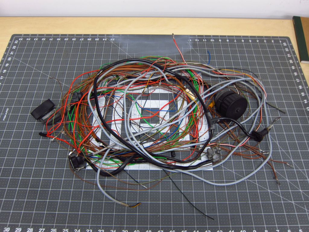
            Here's a picture of what remains of the original harness that will be used going forward...


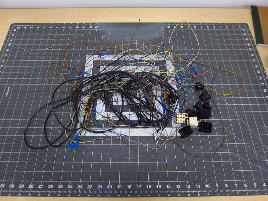
            ...and here is what is being discarded. Well, most of it. I am keeping the relay sockets, which were removed for cleaning & wire re-routing.


            Part of me was tempted to just build a whole new harness from scratch, but that would have ended up being a few hundred dollars in needless extra cost. The stock wire has PVC insulation as far as I can tell, which is not amazing or anything, but it is perfectly fine for an engine harness. The new wire I have ordered all has Tefzel (ETFE) insulation, which is considerably sturdier while also allowing for thinner wall thickness. Smaller overall wire diameter makes for slightly easier routing, and since I am going to be increasing the number of wires coming from the ECU plug by 28, I want to have some extra help in being able to fit them all out of there!

            Transaction Feedback: LINK

            Comment


              #36
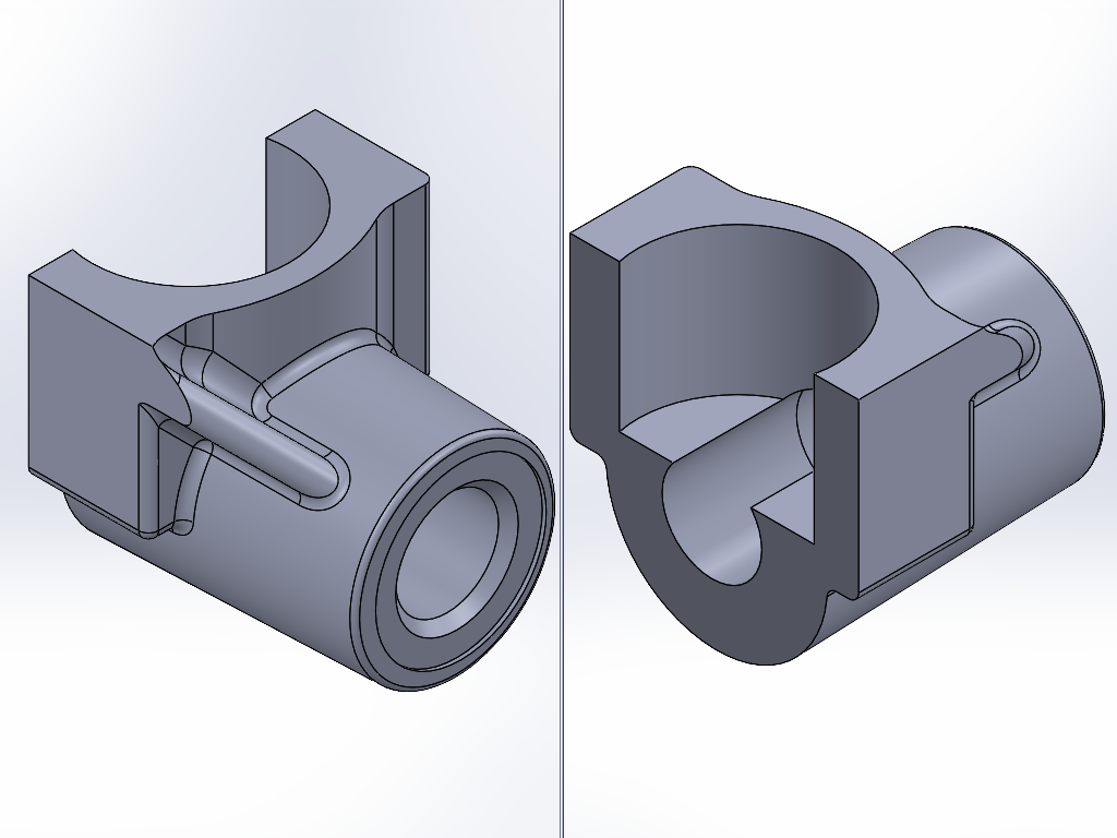
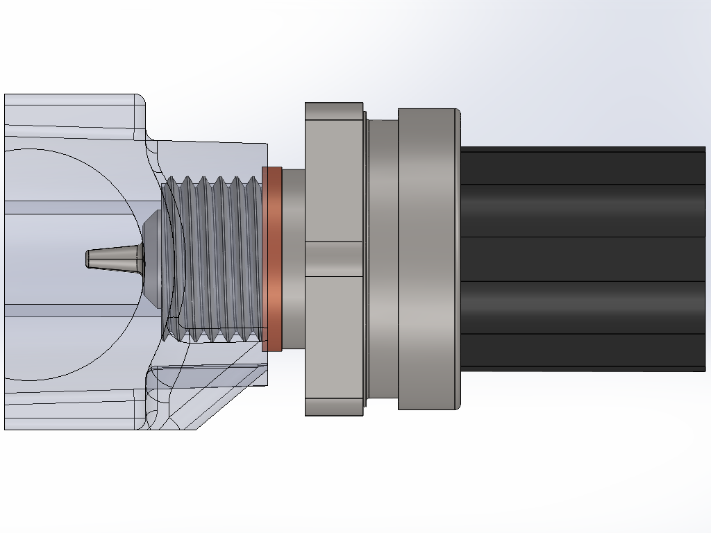
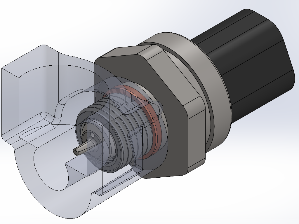
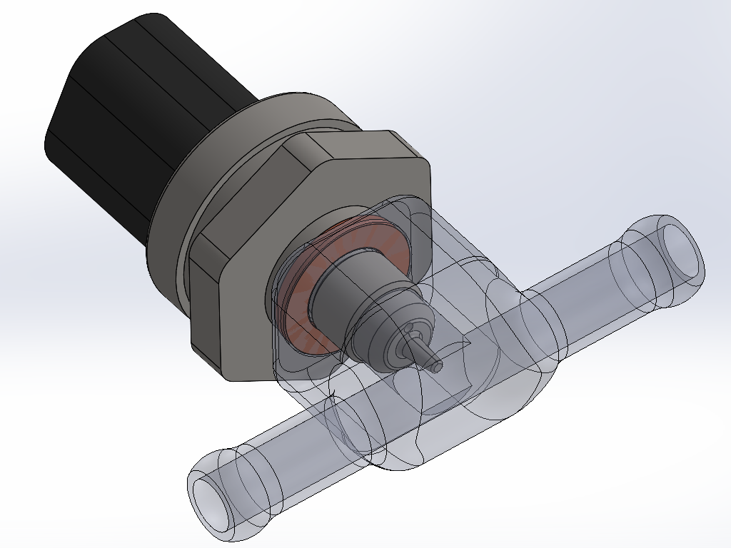
              Today I started in on some CAD for adapting the Bosch pressure/temperature sensors to fit on the engine. The one for the oil will go in the oil filter housing where the stock pressure switch was. Since the existing hole is M12x1.5, and the sensor is M10x1, I need to drill it out a bit larger and install a thread repair sleeve. It is also a bit longer than I'd like since (ideally) the thermistor tip in the sensor would be in the actual flow of oil. I can't trim it enough to get the sensor that far in, but I can certainly get it a bit closer. I got out the calipers and made some measurements with which I modeled the threaded boss area. The main limiting factor for pushing the sensor further in is the big open cavity inside where the oil bypass valve is (the one that should never open unless somehow the filter gets totally clogged).


              So with a little trimming that can all be done pretty easily on a manual mill, here's how the sensor will end up fitting in there.


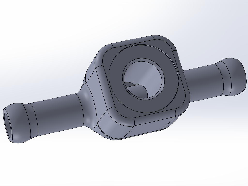
              For the fuel sensor, I am planning to have a little inline tee fitting CNC machined from some 7075 aluminum rectangular bar stock I have laying around. This will install into the 8mm ID hose that feeds fuel into the rail, as close to the rail as I can get it. I'd expect the fuel to heat up minimally overall since it flows at a fairly high rate and has a lot of metal tubing to dump heat from between the front & rear of the car, and it probably does not spend enough time in the rail to significantly heat up much more after the sensor, so I figure I will get a decent reading of it like this. The other option was to get a spare fuel rail and have a friend TIG a little threaded boss onto it, but that seems very unnecessary, and would be a pain in the butt to access if I needed to replace the sensor.


              The other open items I have are to figure out where & how to mount the M50 ICV, and how to mount the MAP+IAT sensor. I'd like to fit the ICV in approximately the same location as the original, but it is pretty tight and will likely require even more custom machining. The other option is to mount it vertically in the open(ish) area behind the intake boot and a little to the left of the intake manifold. For the MAP+IAT, I am thinking I am going to mount it on the rear-most sloped face on the top of the intake manifold since that is the only spot I where I am confident that it'll clear the hood insulation. Maybe I will try sticking some foam blocks on the top flat part to see if I can clear the insulation closer to the middle, but it seems iffy. Either way, it needs 9~10mm of material thickness to get a seal with the o-ring it uses, so I will need to machine a little mount plate or flanged sleeve or something.

              Transaction Feedback: LINK

              Comment


                #37
                Originally posted by bmwman91 View Post
                Today I started in on some CAD for adapting the Bosch pressure/temperature sensors to fit on the engine. The one for the oil will go in the oil filter housing where the stock pressure switch was. Since the existing hole is M12x1.5, and the sensor is M10x1, I need to drill it out a bit larger and install a thread repair sleeve. It is also a bit longer than I'd like since (ideally) the thermistor tip in the sensor would be in the actual flow of oil. I can't trim it enough to get the sensor that far in, but I can certainly get it a bit closer. I got out the calipers and made some measurements with which I modeled the threaded boss area. The main limiting factor for pushing the sensor further in is the big open cavity inside where the oil bypass valve is (the one that should never open unless somehow the filter gets totally clogged).


                So with a little trimming that can all be done pretty easily on a manual mill, here's how the sensor will end up fitting in there.


                For the fuel sensor, I am planning to have a little inline tee fitting CNC machined from some 7075 aluminum rectangular bar stock I have laying around. This will install into the 8mm ID hose that feeds fuel into the rail, as close to the rail as I can get it. I'd expect the fuel to heat up minimally overall since it flows at a fairly high rate and has a lot of metal tubing to dump heat from between the front & rear of the car, and it probably does not spend enough time in the rail to significantly heat up much more after the sensor, so I figure I will get a decent reading of it like this. The other option was to get a spare fuel rail and have a friend TIG a little threaded boss onto it, but that seems very unnecessary, and would be a pain in the butt to access if I needed to replace the sensor.


                The other open items I have are to figure out where & how to mount the M50 ICV, and how to mount the MAP+IAT sensor. I'd like to fit the ICV in approximately the same location as the original, but it is pretty tight and will likely require even more custom machining. The other option is to mount it vertically in the open(ish) area behind the intake boot and a little to the left of the intake manifold. For the MAP+IAT, I am thinking I am going to mount it on the rear-most sloped face on the top of the intake manifold since that is the only spot I where I am confident that it'll clear the hood insulation. Maybe I will try sticking some foam blocks on the top flat part to see if I can clear the insulation closer to the middle, but it seems iffy. Either way, it needs 9~10mm of material thickness to get a seal with the o-ring it uses, so I will need to machine a little mount plate or flanged sleeve or something.
                FYI I don't know if there is much of an advantage to mounting the oil pressure sensor such that it actually sits in the oil flow anyway - I have a PTS-f1 on oil, coolant and fuel and my oil one is on a roughly 2" long fitting adapter adventure/future turbo oil tee (this is on an M20).

                Pressure response seems to follow RPM exactly, at least with less than 50ms lag, which is the fastest I have bothered logging, and temperature is relatively slow to change, so even the relatively minimal flow at the actual sensor tip looks like it gives me a good reading.

                One thing though - all my pts sensors seem to suffer from the same noise glitch on the temperature line. It is pretty infrequent but I have them pretty heavily filtered digitally on the MS and it still gets through, so you may want to consider a hardware filter of some sort as well. Pressure seems completely fine, even with minimal filtering. I do need to re-route my plug wires though, which I think is the source of my noise, so maybe it is just a me problem.

                Comment


                  #38
                  Thanks for the info, that is super helpful. So you are saying that you have the oil PST-F1 sitting in stagnant oil at the end of a ~2" fitting where there is no net flow? If so, then maybe I will do a really minimal amount of trimming on the housing, or make an adapter that works with the existing M12 thread and sticks out a bit further to accommodate the M10 thread.

                  As far as the noise on the temperature line, that makes sense. It is just a resistor divider, meaning a high impedance leg between the ECU and sensor, so it'll for sure pick up ignition noise and stuff. You are saying that you see it irregularly though? That is sort of odd. Got any log captures that show what the signal looks like?

                  Transaction Feedback: LINK

                  Comment


                    #39
                    Originally posted by bmwman91 View Post
                    Thanks for the info, that is super helpful. So you are saying that you have the oil PST-F1 sitting in stagnant oil at the end of a ~2" fitting where there is no net flow? If so, then maybe I will do a really minimal amount of trimming on the housing, or make an adapter that works with the existing M12 thread and sticks out a bit further to accommodate the M10 thread.

                    As far as the noise on the temperature line, that makes sense. It is just a resistor divider, meaning a high impedance leg between the ECU and sensor, so it'll for sure pick up ignition noise and stuff. You are saying that you see it irregularly though? That is sort of odd. Got any log captures that show what the signal looks like?
                    Agreed, the temperature sensor would be the most likely candidate to to get pushed around. Maybe I should change the resistor I used for the oil and fuel sensors... coolant has a different one (which is actually internal to megasquirt which seemed like too much effort to change, and is not the exact value Bosch recommends, so I had to do a bunch more work setting up the adjusted curve and validating it which obviously ended up being way more work than changing a resistor) and seems to get hit way less. However, the MS may also just be doing more dramatic filtering, as it is known to be a temperature input which won't rapidly fluctuate.

                    Thankfully I do have data - I can send you actual megasquirt log files if you are equipped to view them and interested, but here are a couple of snapshots:

                    This was taken during a cruise the other day, trying to sort out an idle issue (which is actually IMO due to issues with an FPR, but a replacement has been sent and I will know soon). I have it divided into RPM/MAP, oil temp (deg C) and pressure (kPa), fuel (temp and press) and coolant temp and pressure.

                    I quite like the response time of the pressure sensors - this log snapshot does not show it because it isn't zoomed in enough, but the oil pressure follows RPM to within < 75ms, which is the logging resolution I have it set to right now. Coolant pressure also follows very closely, which is to be expected as well with a mechanical water pump, but it is a bit closer to the noise floor and overall pressures are obviously not as high (the log below had a peak of 36kPa/5psi that matched the peak RPM seen of 4k). I have no doubts I could diagnose a failing water pump from the data.

                    Click image for larger version

Name:	log_snip_showing_temp_glitch.PNG
Views:	273
Size:	80.5 KB
ID:	9967095

                    Anyway, there are a couple visible glitches above on fuel and oil temp - and you can see many more below during a warmup from idle, as well as some on the coolant channel. Note that the period I have highlighted, which is essentially how long it takes the oil to warmup to as hot as it will get sitting around idling, is half an hour long - obviously it will warm up faster if you were actually driving, but the oil takes *way* longer to change temperature relative to the coolant (and I have piston squirters, which if anything would speed the process up because they are getting even more oil onto the hot pistons). For reference, in the same log, you can see the coolant warmup to fan turn on (where it flatlines before humping up a bit as I screw with the skinny pedal and idle valve) takes about 360 seconds, i.e. 6 minutes). Anyway, my point is the oil temperature change is somewhat slow.

                    Click image for larger version

Name:	logsnip2.PNG
Views:	228
Size:	93.2 KB
ID:	9967096

                    Now maybe this is due to where my probe sits, in my future oil feed for the blower. One thing though - under continuous highway driving temp seems to drop quite a bit, which is almost certainly due to airflow over the sensor nub sitting there, so a relatively long extrusion like I currently have is not ideal (but I think having the probe a fair bit closer would be more than adequate, really my issue is that the thing is like 2-3 inches long). I mean, I suppose it could be due to the cooler, but I doubt it - the swings I am seeing are ~50c when the car is moving at highway speed and climbing up to 90c after sitting still idling for a little bit.

                    Click image for larger version

Name:	20201017_230025.jpg
Views:	229
Size:	48.6 KB
ID:	9967097

                    Comment


                      #40
                      Interesting stuff.

                      Regarding the resistor value, changing it around is not likely to make all that much of a difference. IIRC Bosch recommends a 4K6 resistor, and I'd guess that MS has a 1K (same as the Motronic also), but it is not all that important as long as the value is known and programmed in. If anything, going to a higher value would potentially make the noise issue even worse, if it is in fact due to EMI from the ignition. It's super weird that it is so much worse at idle than when running though. Anyway, since the CLT temp signal is nice and clean, and as you mention the input is a dedicated "temperature input" I'd guess that there's just a capacitor connecting the resistor-thermistor node to ground to act as a simple first order low pass filter. Which version of MS are you running? You could probably add the filtering capacitor and/or resistor on the mainboard, since it sounds like you added the resistor near the sensor.

                      I am 99% sure that the long warm-up time and cooling effect that you see is due to where the sensor is. Heat will conduct very slowly through the stagnant oil, and passing air will for sure cool that "leg" off. But, since you plan to have oil actively flowing through there when you get the blower installed, that will be a perfectly good place for the sensor at that point. The only point of caution I'd make is that the long assembly of fittings plus the sensor & harness being out that far make for a big resonant structure (think tuning fork). I would guess that the life span of that sensor would be shortened. If there is a way to get that tee fitting closer to the block, I'd try to do it.

                      Transaction Feedback: LINK

                      Comment


                        #41
                        Originally posted by bmwman91 View Post
                        Interesting stuff.

                        Regarding the resistor value, changing it around is not likely to make all that much of a difference. IIRC Bosch recommends a 4K6 resistor, and I'd guess that MS has a 1K (same as the Motronic also), but it is not all that important as long as the value is known and programmed in. If anything, going to a higher value would potentially make the noise issue even worse, if it is in fact due to EMI from the ignition. It's super weird that it is so much worse at idle than when running though. Anyway, since the CLT temp signal is nice and clean, and as you mention the input is a dedicated "temperature input" I'd guess that there's just a capacitor connecting the resistor-thermistor node to ground to act as a simple first order low pass filter. Which version of MS are you running? You could probably add the filtering capacitor and/or resistor on the mainboard, since it sounds like you added the resistor near the sensor.

                        I am 99% sure that the long warm-up time and cooling effect that you see is due to where the sensor is. Heat will conduct very slowly through the stagnant oil, and passing air will for sure cool that "leg" off. But, since you plan to have oil actively flowing through there when you get the blower installed, that will be a perfectly good place for the sensor at that point. The only point of caution I'd make is that the long assembly of fittings plus the sensor & harness being out that far make for a big resonant structure (think tuning fork). I would guess that the life span of that sensor would be shortened. If there is a way to get that tee fitting closer to the block, I'd try to do it.
                        These are all good points - and I definitely agree that the sensor position dangling in the breeze there is less than ideal. Unfortunately aside from whipping up a custom adapter/fitting of some sort I don't know if I have any good and easy options to shorten it, but this may well be what I need to do.

                        I am running an MS3 pro ultimate, which I have not actually found the schematics for, but if it is anything like the MS3 then there is a low pass RC filter on the coolant line. I may well change over the resistor for the other two sensors and see if it helps, but first I plan to adjust my plug wiring significantly.

                        Comment


                          #42
                          Ah, yeah I'd be a little hesitant to hack up an expensive item like that. I'd assume that it has a number of "temperature inputs" so could you just re-pin the connector at the ECU to run those in through them instead of regular analog inputs?

                          Transaction Feedback: LINK

                          Comment


                            #43
                            Originally posted by bmwman91 View Post
                            Ah, yeah I'd be a little hesitant to hack up an expensive item like that. I'd assume that it has a number of "temperature inputs" so could you just re-pin the connector at the ECU to run those in through them instead of regular analog inputs?
                            Aside from the CLT input, it does not have dedicated temperature inputs, just ADC channels. I may just spin up a little board for inline, I am probably going to be pulling the trigger on my first run of cluster boards in a few weeks here anyway and I could definitely fit it on the panel somewhere. The more I think about your comment regarding sensor lifetime the more I want to revisit that though... having the weight of an oil line and restrictor also hanging off that seems less than ideal. Maybe I will try drilling and tapping in directly an AN 6

                            Comment


                              #44
                              Wow, I am a bit surprised that they didn't have more dedicated temperature inputs. Thermistors sensors are pretty well known to have noise issues due to their high impedance. But it sounds like you know how to tackle that.

                              Assuming the hole you have everything mounted into is M12, then drilling & tapping for an AN6 (9/16-18) fitting is a good call. I had considered the same thing myself since the oil pressure switch in the M42 oil filter housing is also M12. Heck, I guess I will be tapping it with 9/16-18 threads since that is what the M10 thread insert has on the outside. Too bad BMW did not specify a switch with an M14 thread...

                              Transaction Feedback: LINK

                              Comment


                                #45
                                Yeah, my adapter for the PTS is an AN 6 on both ends (one is capped and will obviously feed the turbo) with an M10 port on the side - I should be able to re-drill and tap that hole exactly as you mentioned. I will get the car on the lift this weekend, and I need to drain the oil anyway, so it is a perfect time to give it a shot. That will at least be mechanically more sound, even if for the time being the oil temp reading will likely still be low until I get around to the blower. I am not tracking the car for quite a while yet though, so I am really not concerned about oil temps.

                                I don't know how many fittings you are planning on designing/manufacturing, but I had good success ordering some bits from https://www.efisolutions.com.au/ in Australia, at least bits specifically designed to adapt the Bosch PTS sensors to AN (and other things).

                                Comment

                                Working...
                                X