
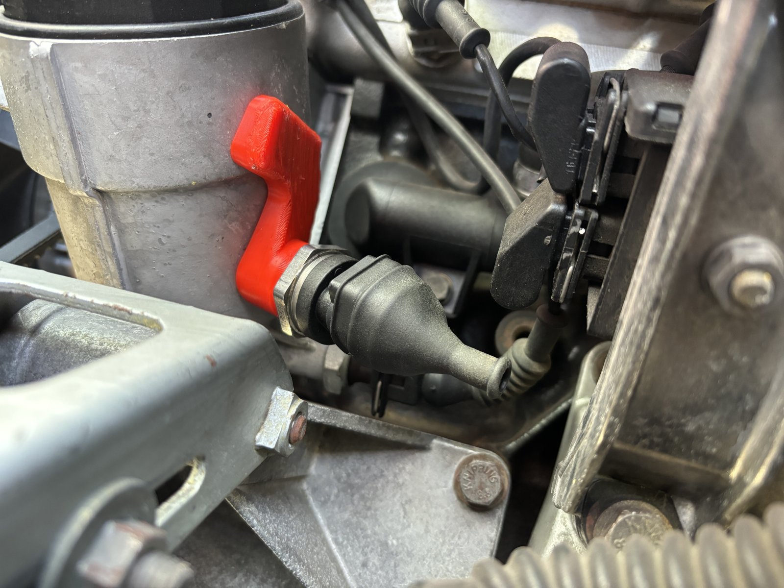
I have had this project on the backburner a bit, but there has been a little progress on the final few details. One thing that I have never quite felt satisfied with is the location of the oil pressure + temperature sensor. The plan was to stick it in the back of the head in where the main oil feed gallery plug was. The location is sort of tight, I'd never be able to get thread locker to properly work since I cannot get the threads oil-free without pulling and draining the head, and the oil at that spot is going to be pretty stagnant so the temperature readings would probably be driven more by the coolant temperature than the oil temperature.
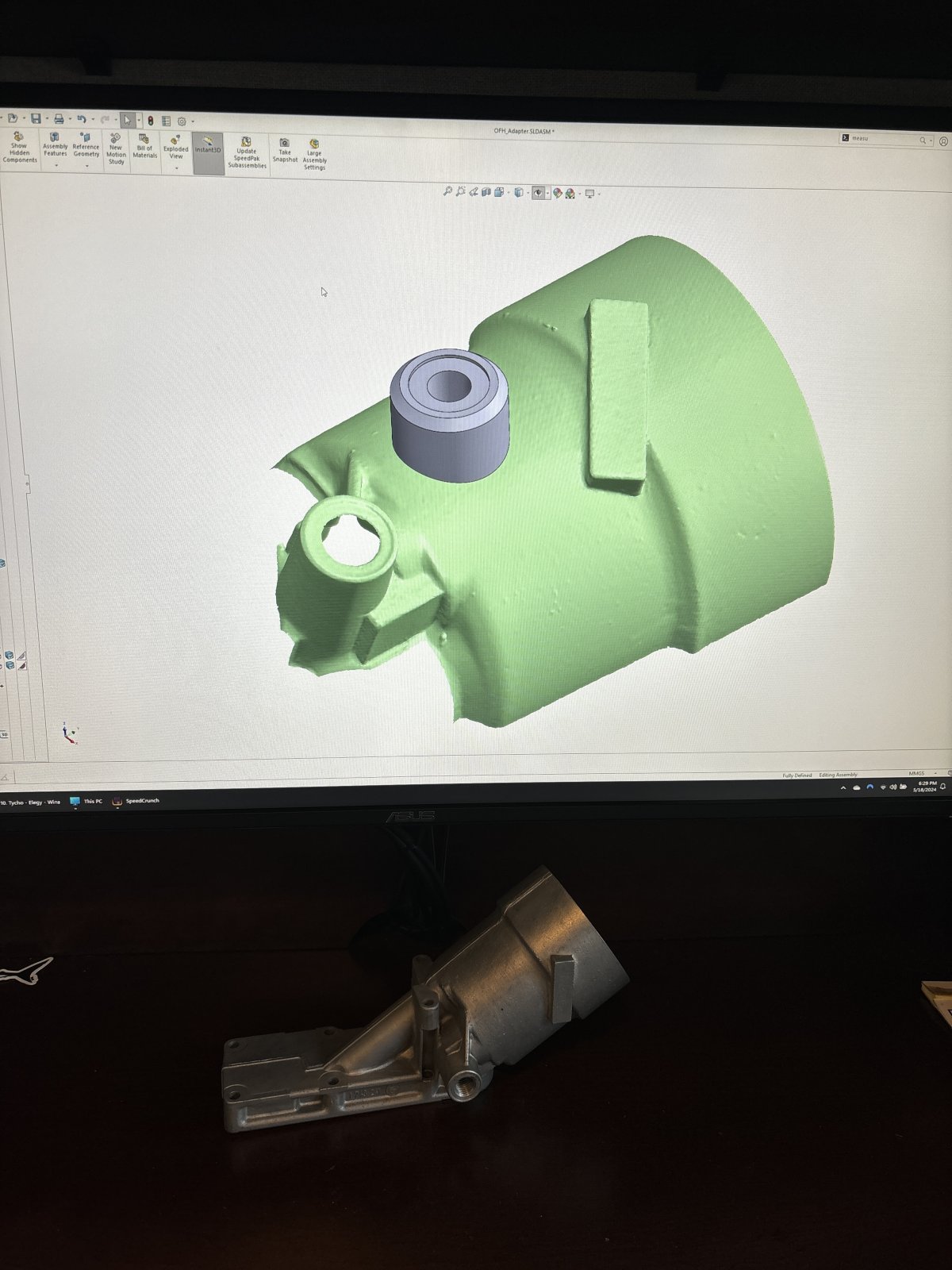
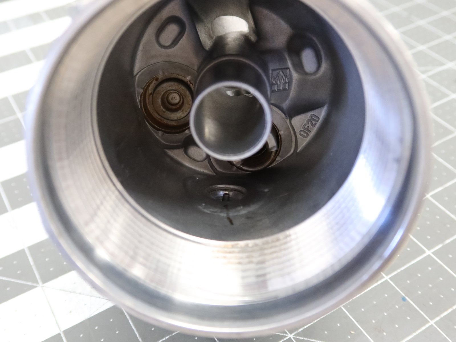
Since I have a spare oil filter housing, I 3d scanned it and made up a little adapter bung for the sensor. This will guarantee that there is constant oil flow past the sensor, and it should give a good read on the oil temperature as it comes up out of the pan. It isn't ideal to have it on the dirty side of the filter since the clean side will read a little lower, but I am not really planning on letting the filter get so dirty that it clogs up lol.
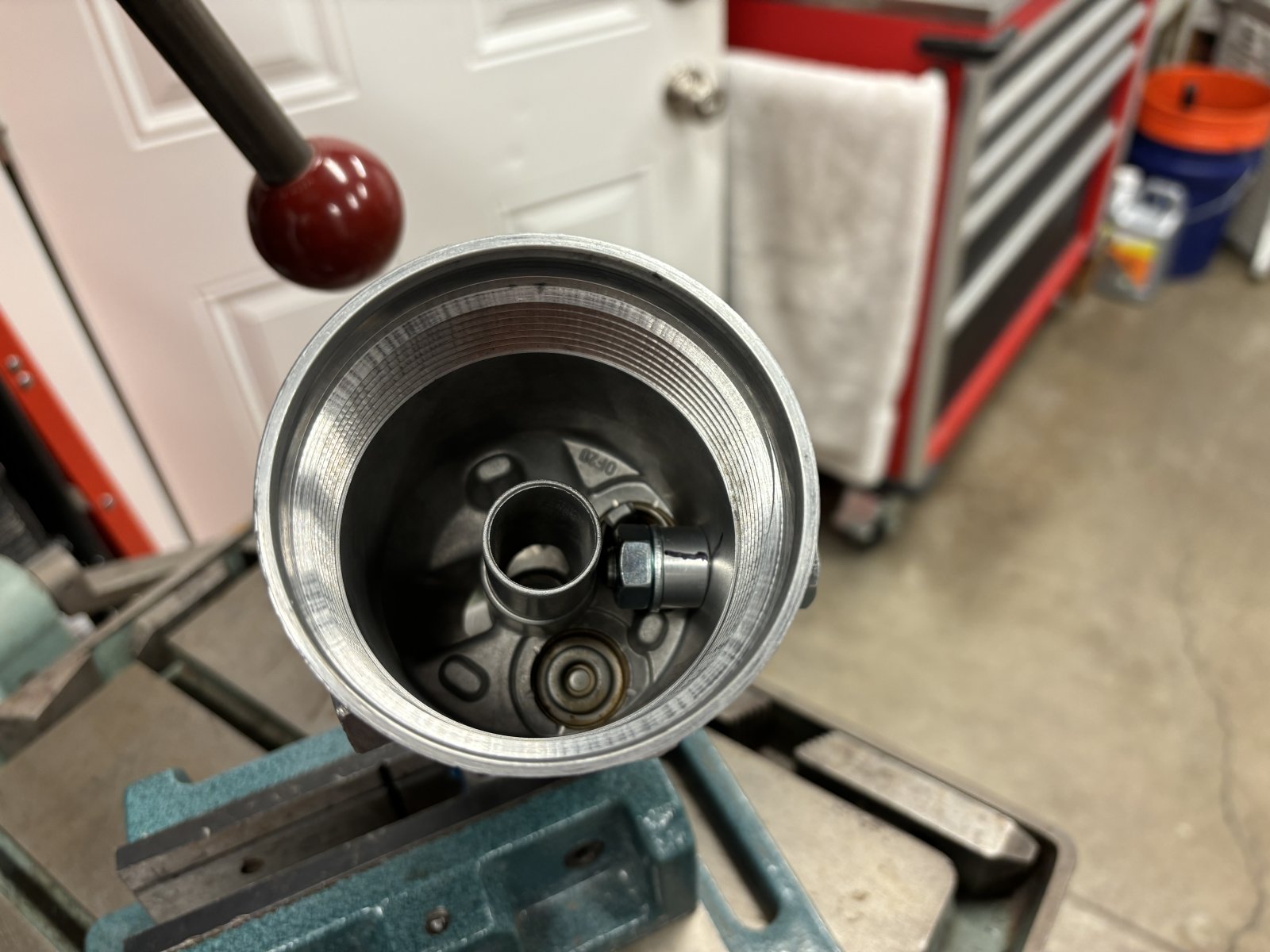
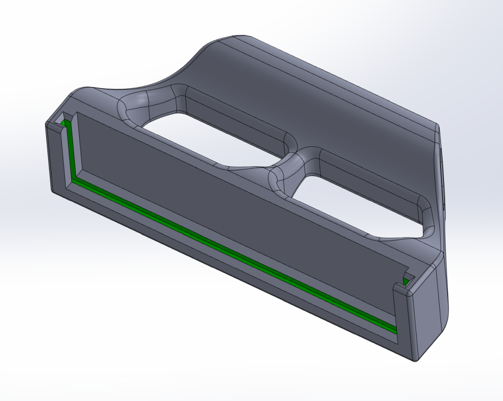
I 3D scanned the filter housing and came up with an adapter bung. Along the way there were some 3D printed locating fixtures that allowed me to get the sensor position dialed in on the housing that is currently on the engine under the hood.
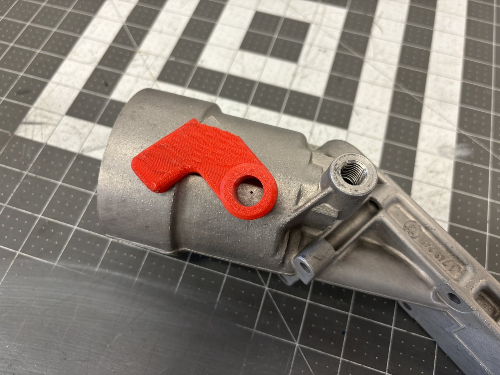
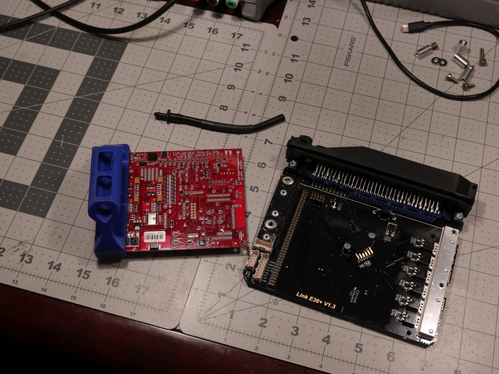
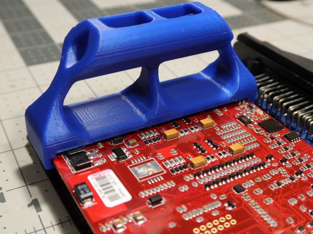
Here's the deal with the 3D printed positioning fixtures. It was used for both figuring out the sensor position, and as a drill guide.
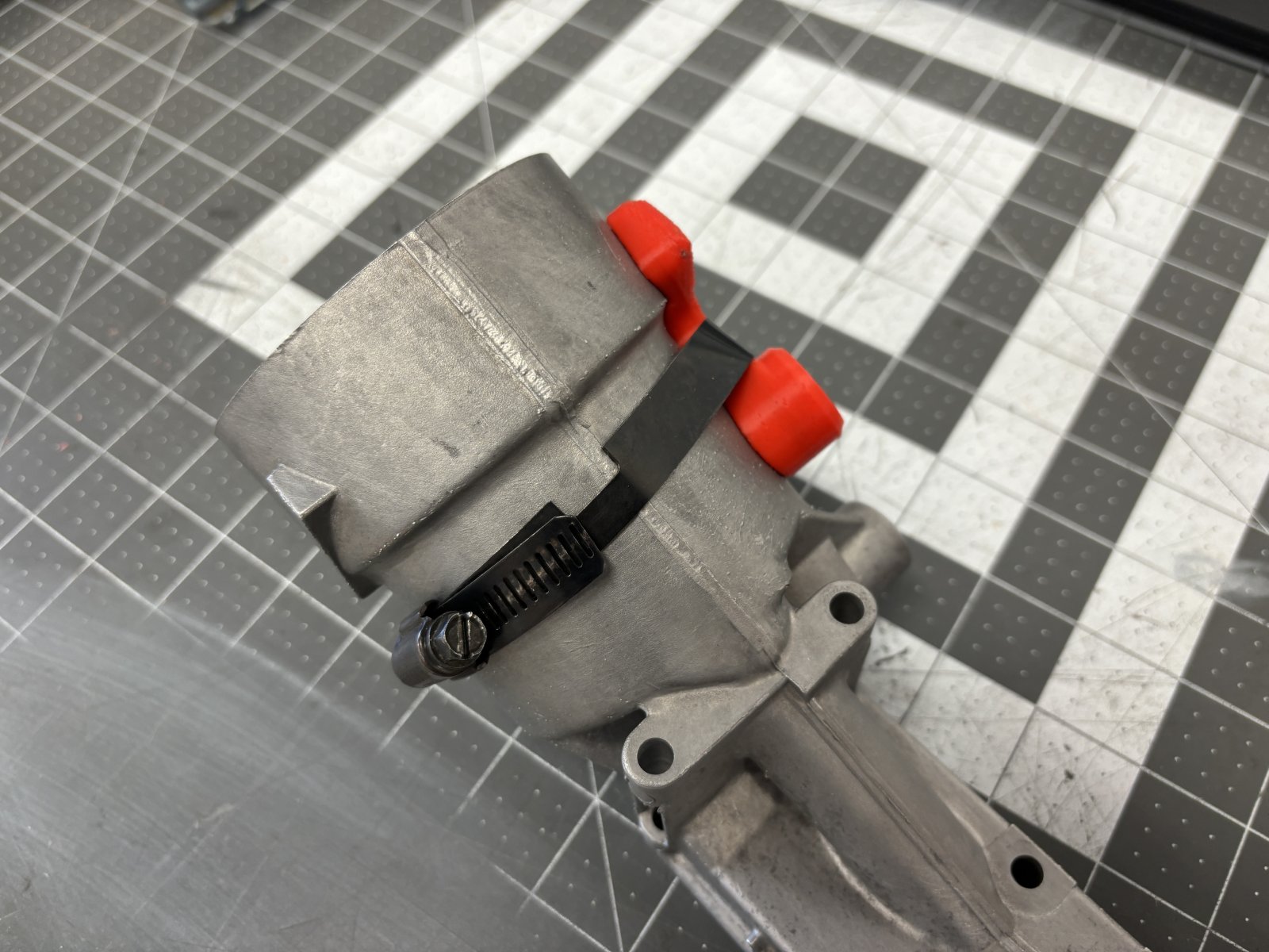
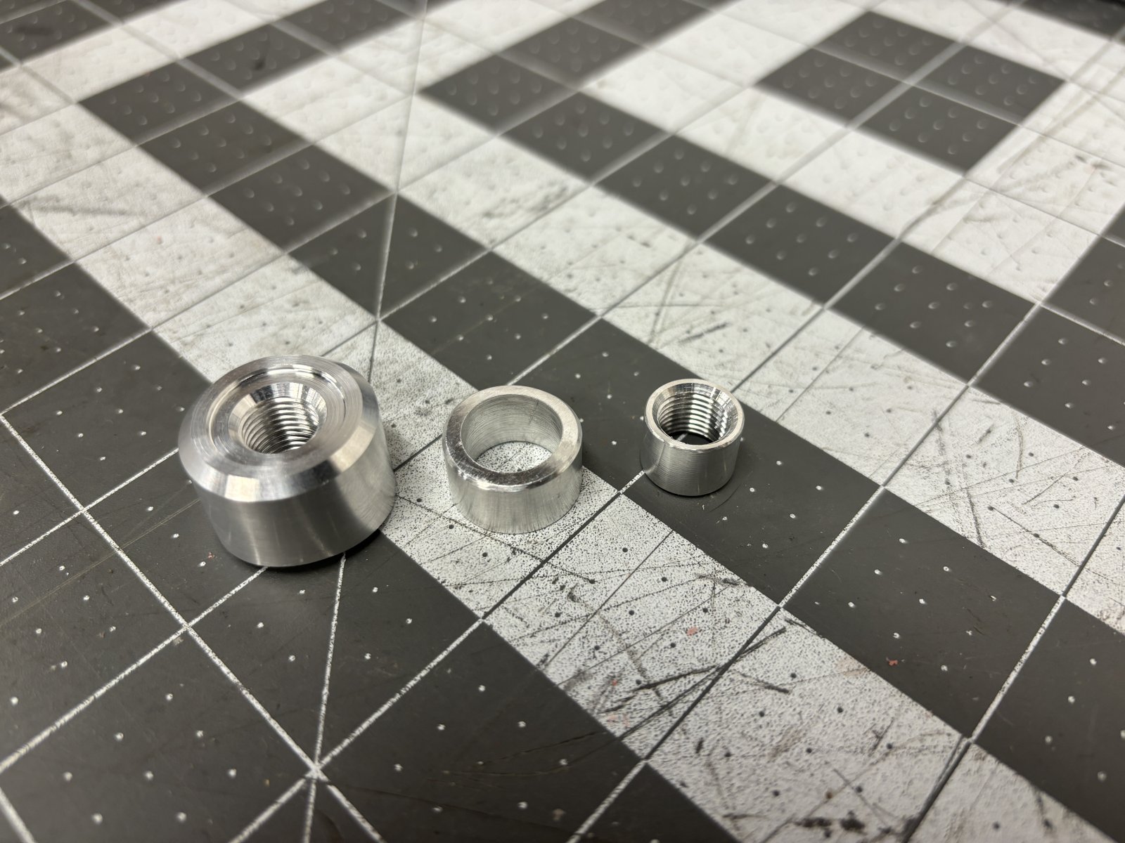
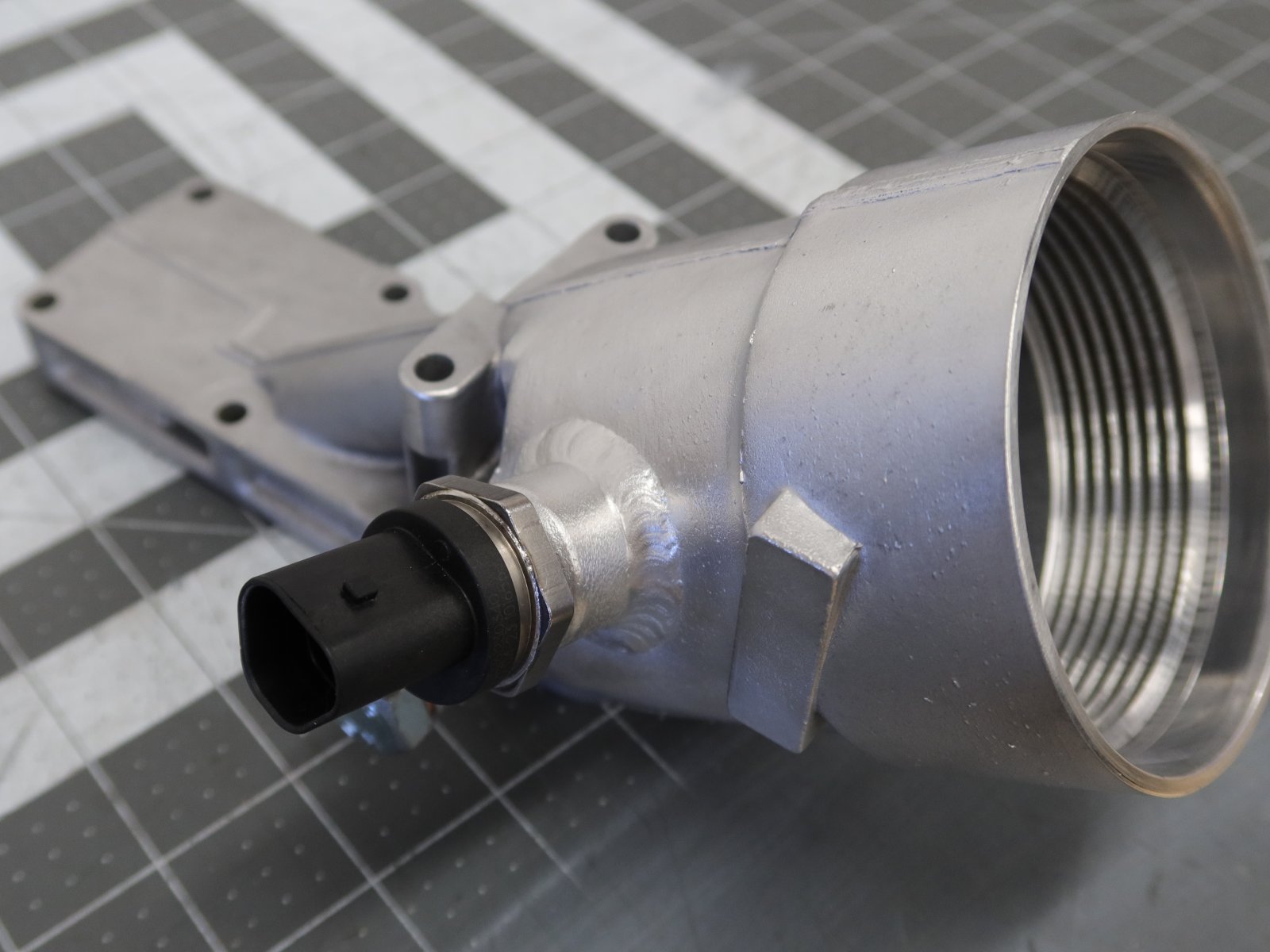
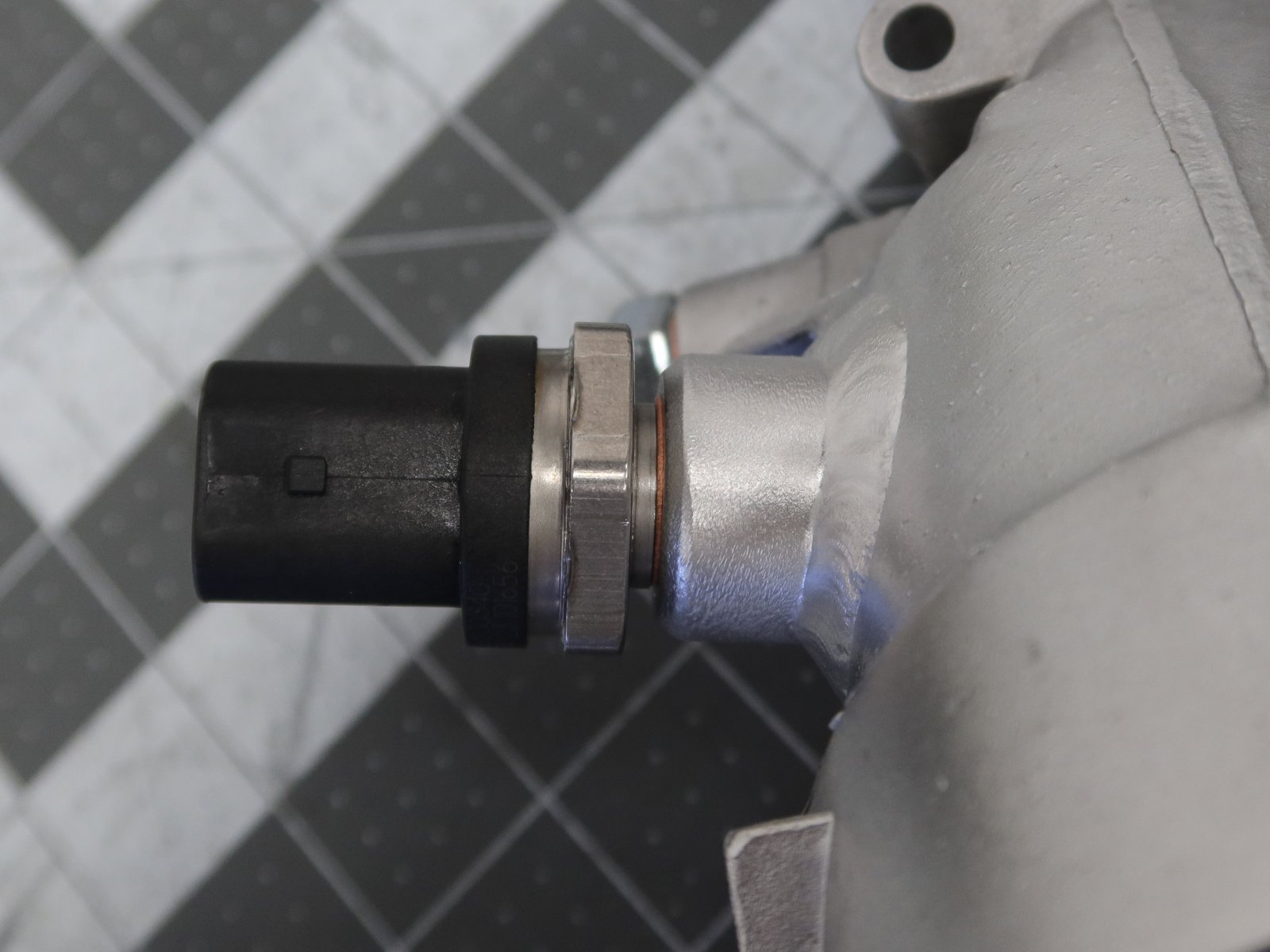
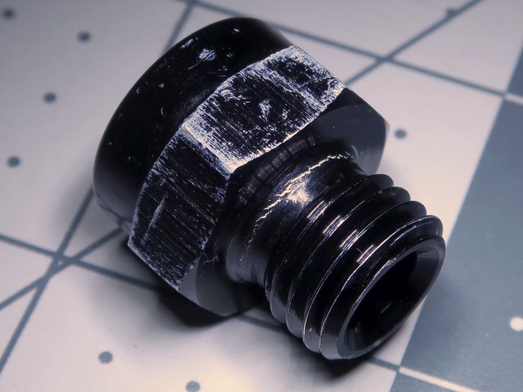
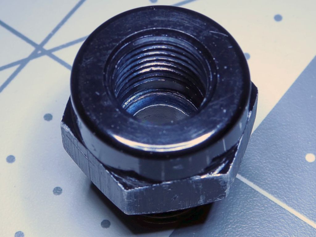
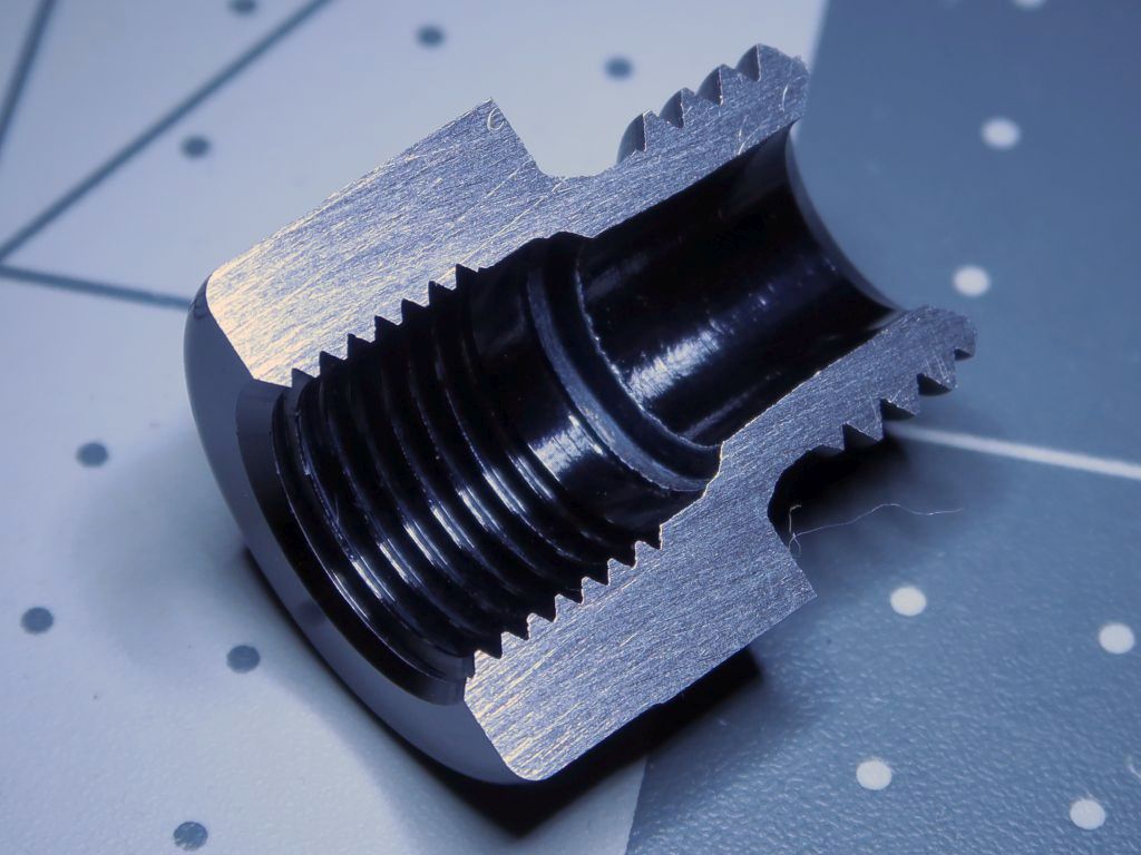
I machined up the adapter bung as well as some extra little fixture pieces that would secure it in place while it was being welded onto the filter housing.

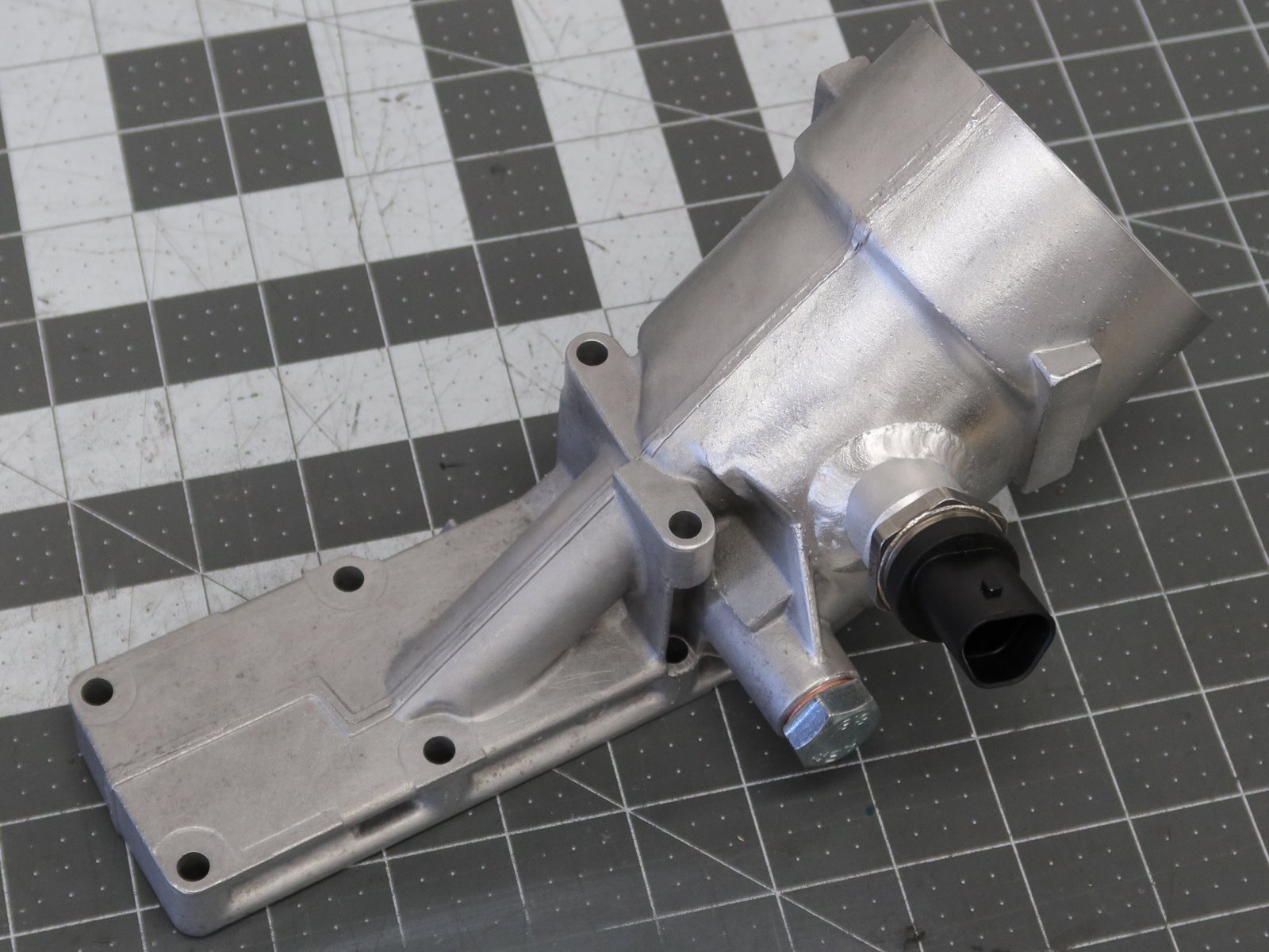
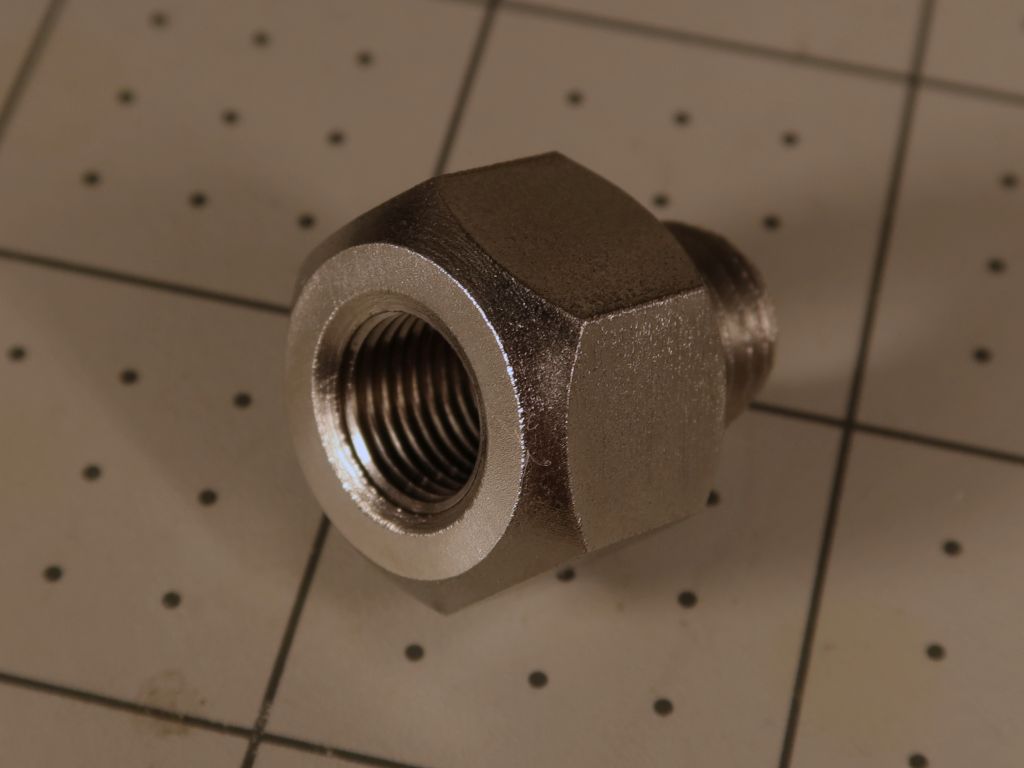
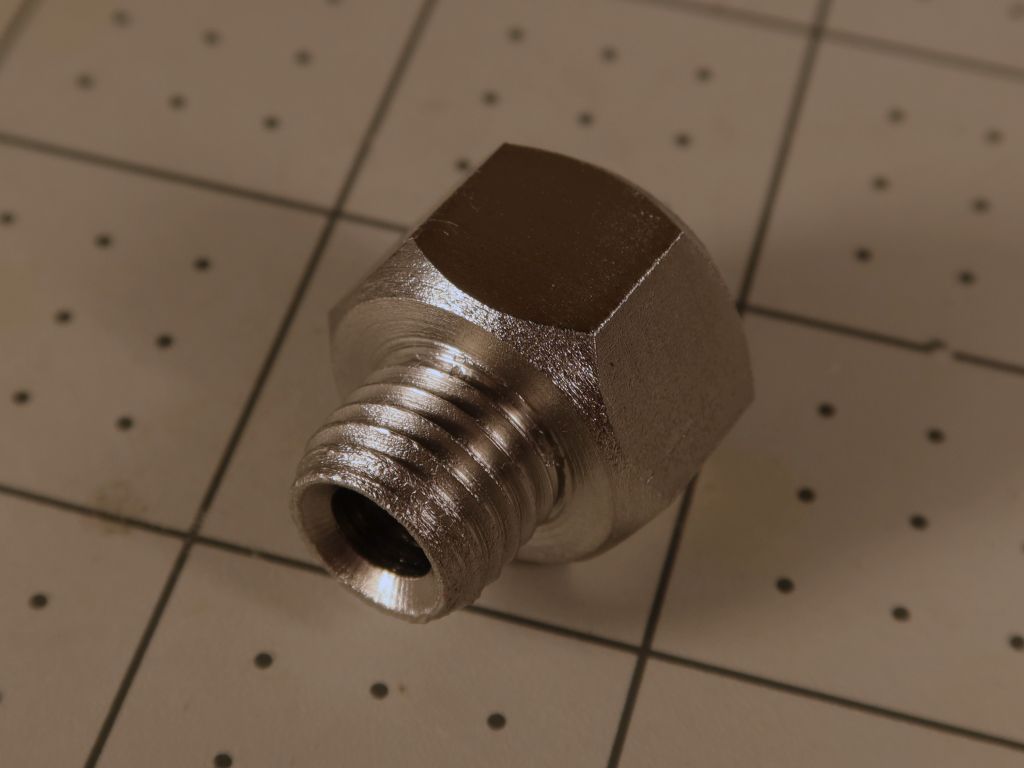
And here's the final product after welding. I had the guy that repainted my E30 do the TIG work for me since I suck at it, particularly with aluminum! Now I will just need to get the gasket and o-ring for this and install it on the engine once I am ready to swap on the new harness and ECU. I also reworked the harness a little to reroute the sensor wires so that they come out of the front of the wire box in a more logical location.


Leave a comment: