-
Awesome, can't wait to see it done! I'm just going to live vicariously through you to satisfy my 2.8 needs if that is alright ;p-AlexComment
-
Good to see you on the machines doing it yourself. Hope it all goes well for you.
Just curious on what you do for a living. It's good to see you teaching and going over the processes undertaken when machining these parts which makes it an interesting read the few of us who aren't in the trade.
My guess would be your a fitter and turner of some sort.
Comment
-
Wow, nice work.Comment
-
Couple of things about this thread that made me, as an Aussie, smile:
- you use the term "in the bush"
- your picture of snow coverage is "one of the not so cold days"
I am now subscribed and looking forward to how this goes. Keep on with the great pics and narrativesigpic
1988 Lachssilber E30 325i sedan.
Factory fit-out: manual; SILBER LEDER; M SPORT SUSPENSION.
Modifications so far: Miller MAF + 19# ECU; Ford 19# Design 3 injectors; IE adjustable FPR; KAMotors CF airbox; IM MTX-L; EBC Greenstuff.
Retired - '83 Arctic Blue E28 528i powered by M30B32
Comment
-
For a living, currently I'm a mechanical designer for a small company that makes special purpose lifting equipment. I received my degree in mechanical engineering last year and just started working this past December. Unfortunately they don't teach you how to run machines as part of the degree requirements. The machining experience comes from the two summers I worked in a machine shop while I was in high school.
Cheers mate :up:Comment
-
The mediation pic had me rolling. Enjoying the step by step progress really allows everyone to visualize whats involved.
I want to build a 2.8 stroker as well but sometime in the future. Will definitely be referring back to this for guidance!!!IG: deniso_nsi Leave me feedback here
Comment
-
so youre not going to port your intake side? you say it worsens the flow...what do you mean?
just trying to learn here.....I read every stroker thread I can
Comment
-
I'm only going to gasket match it and that's it because I don't know enough about how to modify the port geometry to improve the flow and I don't have access to a flow bench. If you start messing around with the intake side you can do more harm then good pretty quickly if you don't know what you are doing, and without a flow bench to test there's really no point in trying. The one thing I know for sure is that polishing the intake ports is a mistake because you actually want that little bit of roughness to help promote turbulent flow so that fuel and air will mix. A smooth port will give you high velocities but poor atomization of the fuel, that's why it's ok to polish the exhaust side because all you care about at that point is getting the exhaust gasses out as fast as possible. This thread has some good information http://www.e30tech.com/forum/showthread.php?t=55675Last edited by Bullet Ride; 03-29-2012, 04:17 PM.Comment
-
Your last statement you wrote about not polishing the intake is mostly true. The rough finish helps prevent fuel fallout. In the olden days hot rodders used to leave a lip between the manifold and port entry because the fuel would come in and be kicked up over the lip thus helping the fuel to enter the chambers in a vapour form (which is good). At the time they didn't know why the engines were making more power they just thought it was one of Gods many miracles.
On a race engine were everything in the motor is fine tuned to extract every bit of power then polishing heads will further improve power figures. But on your engine or any other street motor we see on this site then a rough finish is the way to go.
But then again your probably better off leaving it alone just because you already have that lip from factory and maybe a gasket match could make it worse if your not porting other areas of the intake ports.Last edited by The Humjet; 03-30-2012, 01:20 AM.Comment
-
Since I don't have gaskets, I haven't looked to see yet whether the port on the intake manifold is smaller or larger than the port on the head. So that in and of it self will be a deciding factor in what I end up doing. But since the intake runner is essentially a nozzle, opening up the front edge just to match the gasket won't hurt the velocity of the flow. It might affect the atomization as you mentioned, but in a fuel injected car it's not really an issue.
One of the things I've noticed about the guys flow testing heads is that they usually just flow test the head without any consideration of what's going on before the head. You can have a head that flows great, but if your intake runner is the diameter of a McDonald's straw the system as a whole is going to flow poorly. Intake runner geometry is a whole other ball game that I'll have to get into when I attempt to build an ITB set-up for this thing...Comment
-
Small update
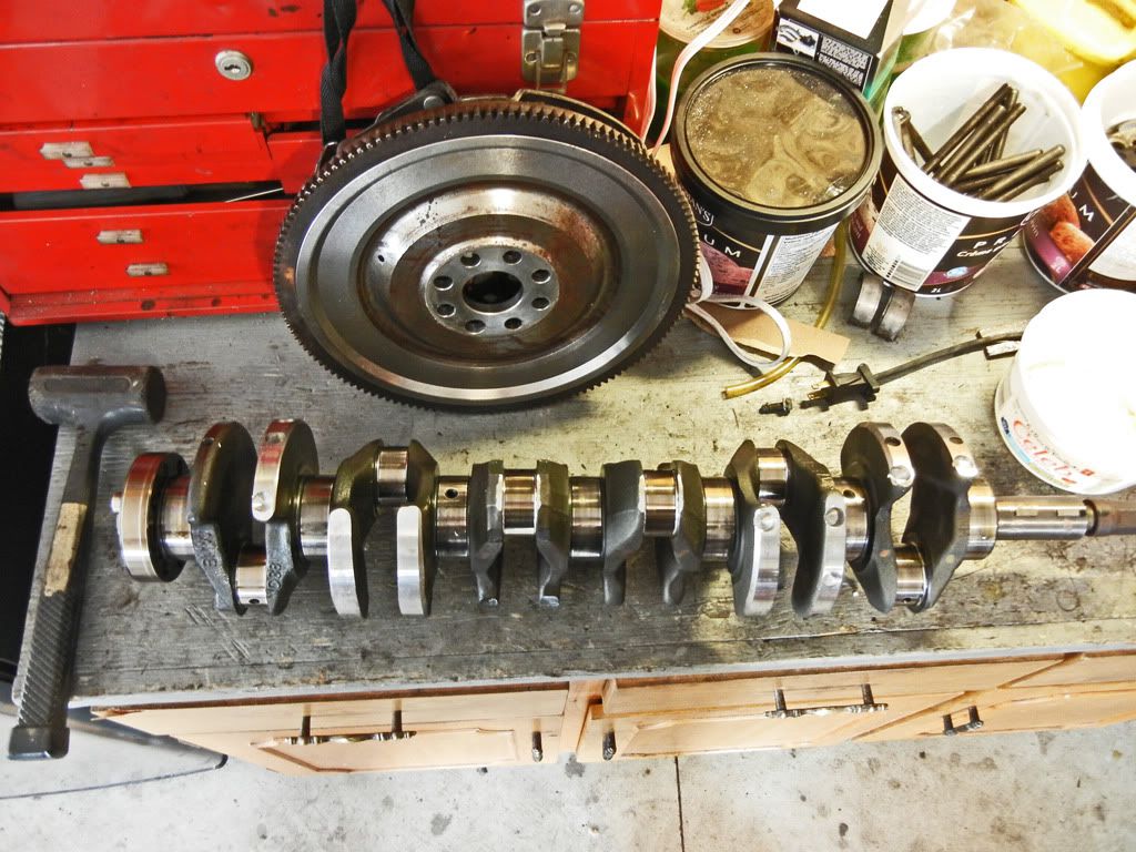
I picked up the crank and flywheel from balancing on Friday.
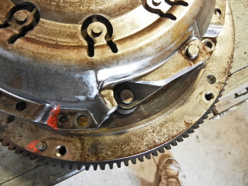
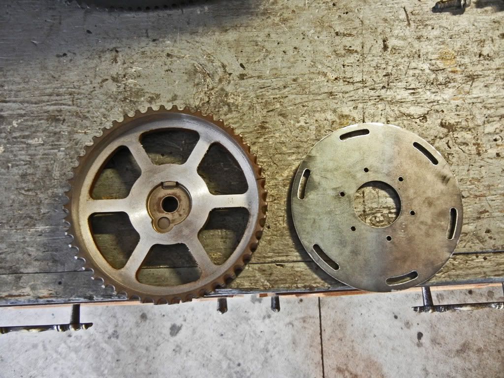
Here is the flywheel and pressure plate. They didn't need too much. You can see a little bit was ground off the edge of the pressure plate and there's one small hole that was drilled into the flywheel.
Here's the crank...
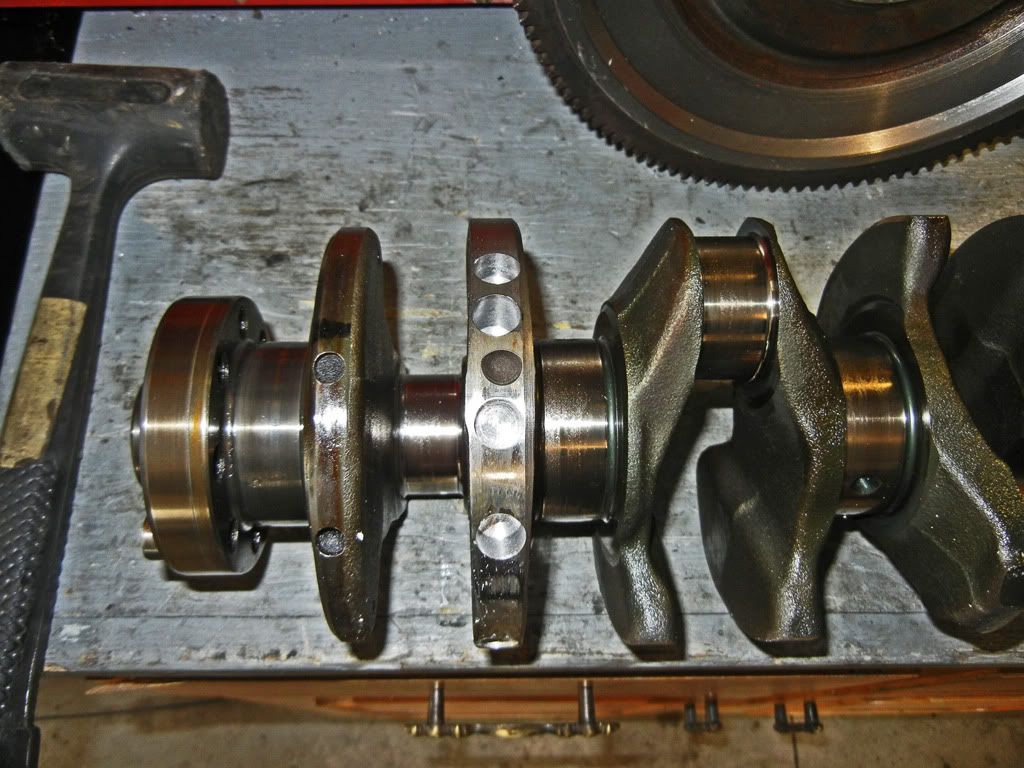
This is what the one end took...
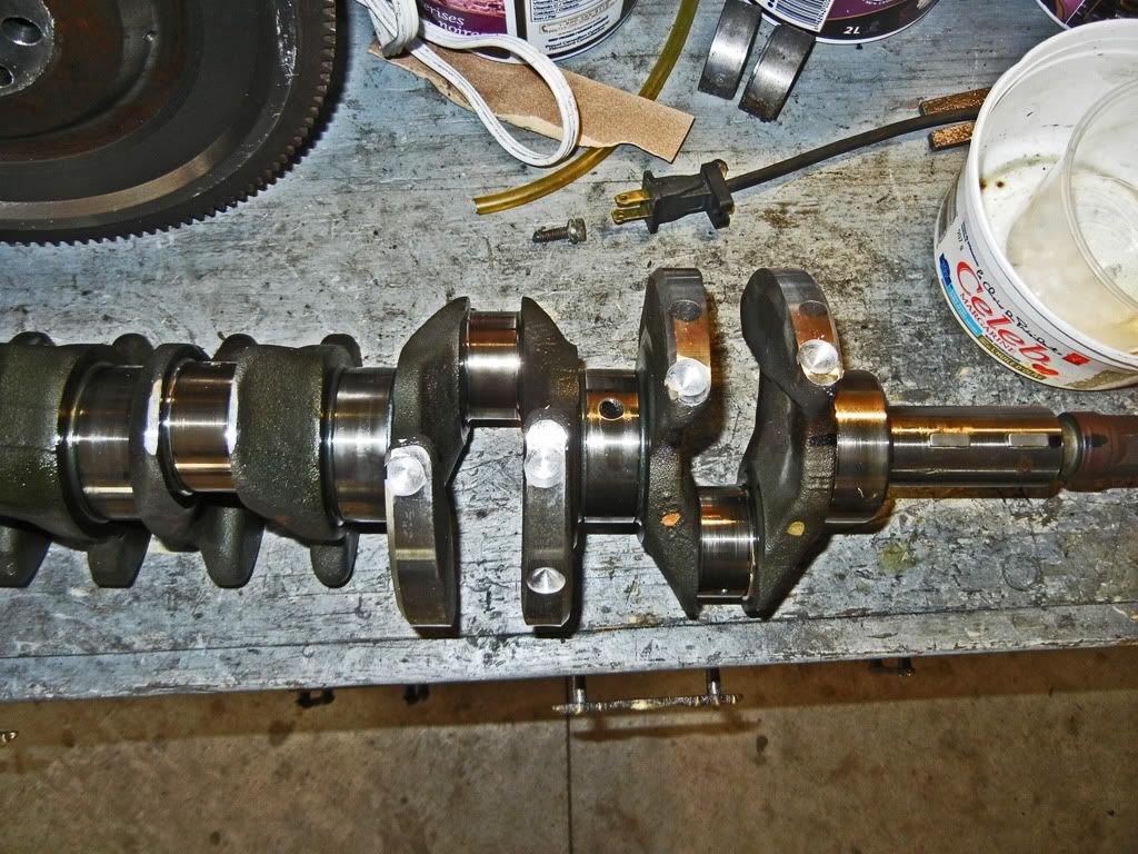
This is what the other end took...
Looking back on when I was machining the crank, when I put the chamfers on the counterweights I just did it by eye because I figured it was just for added clearance and wasn't that critical. However in retrospect I should have measured and made sure all the chamfers were equal because in the end it affects the balance of the crank.
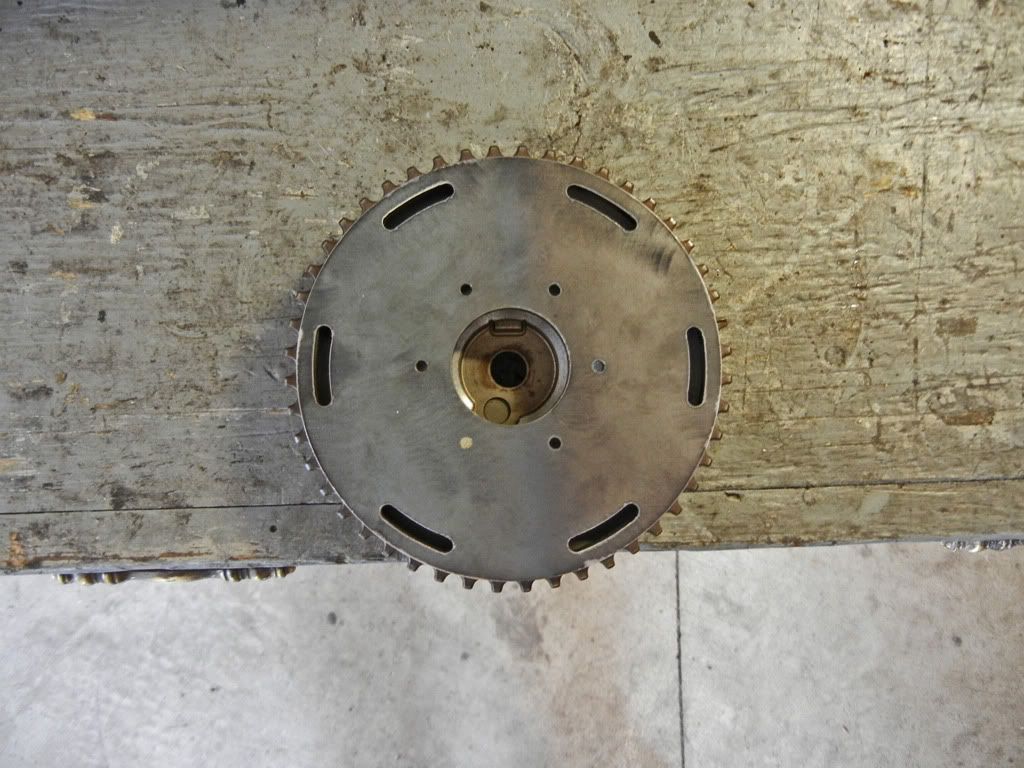
I also got the lasercut for the cam gear however it still needs to be machined.
Comment
-
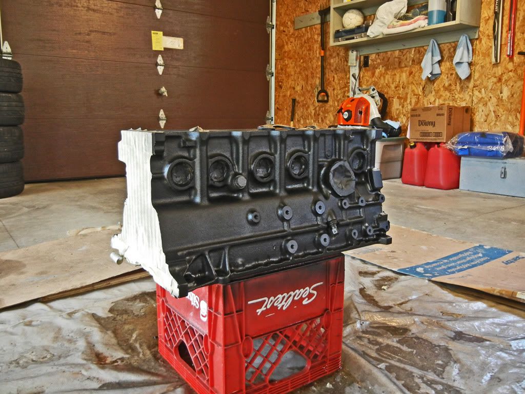
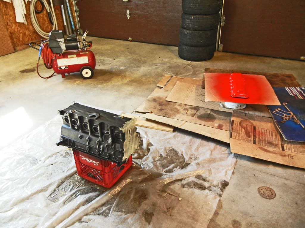
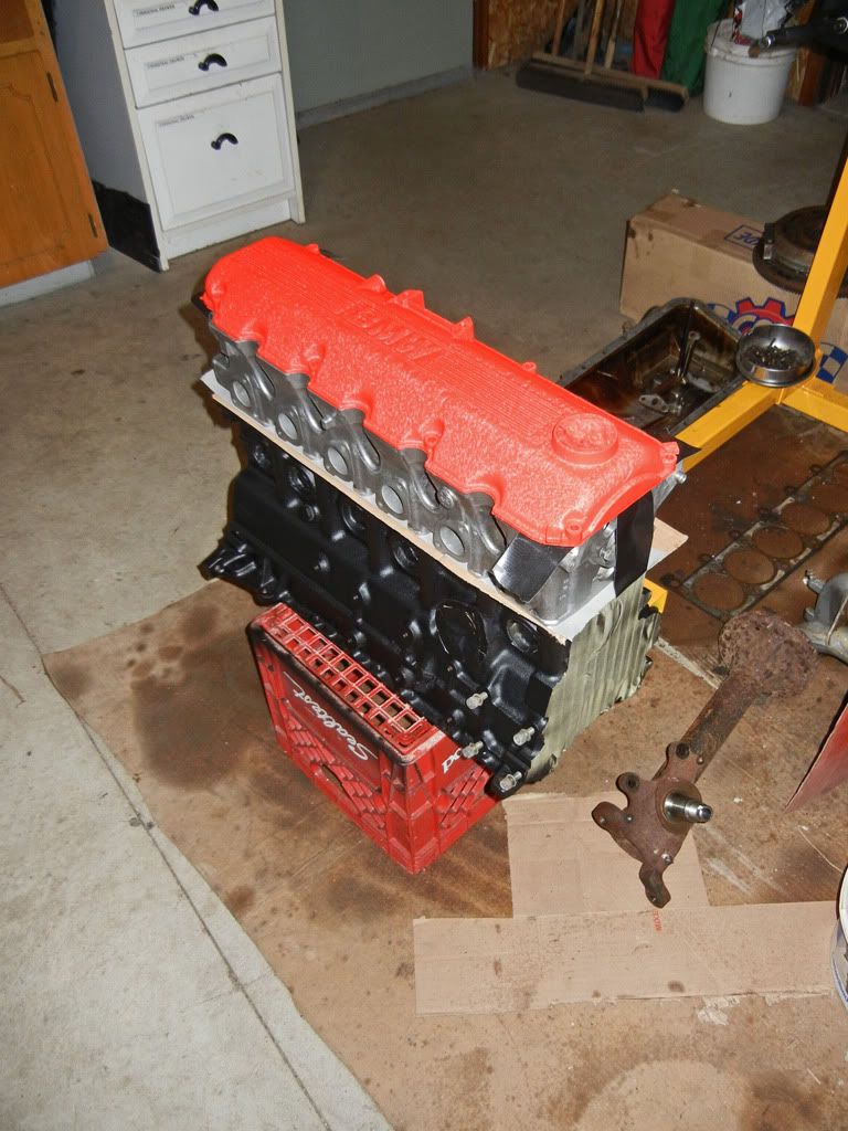
I painted the block and valve cover this afternoon. I used VHT low gloss black engine enamel for the block and VHT wrinkle red (Ferrari stlye :pimp:) for the valve cover
Block scrubbed and wiped down...

After first coat...
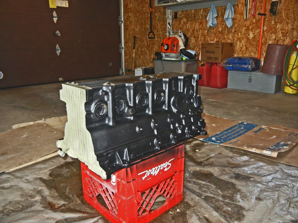
After final coat...
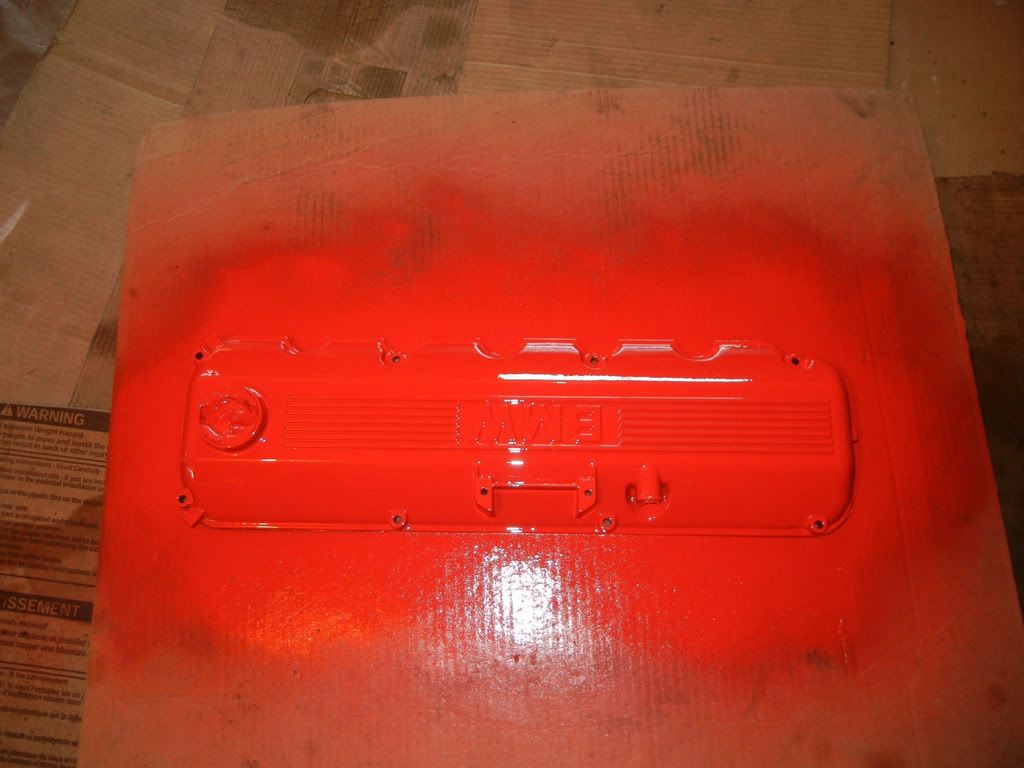
This was right after I sprayed the valve cover, I'll have to wait a few hours to see how the wrinkle turns out. Once it's cured I'm going to sand the paint off the raised parts of the valve cover to give it a nice machined aluminum look...
All the parts I need to start assembling the motor have been ordered. I hope to have them within the next couple weeks.Comment
-
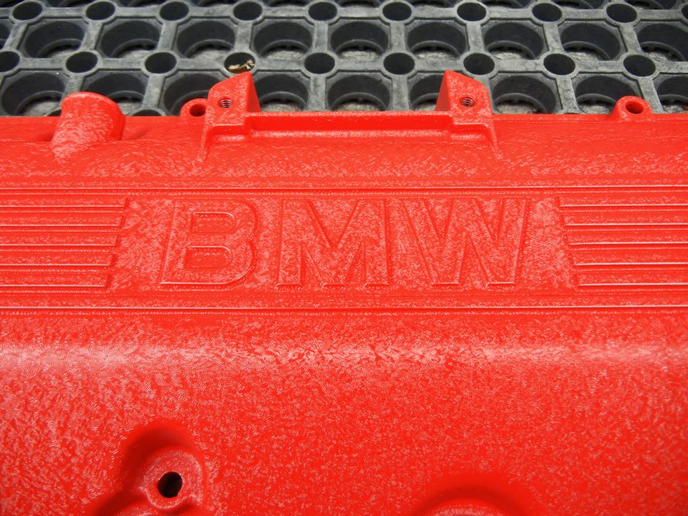
I went out this morning to check on my wrinkle...
Oh how sweet the wrinkle is...
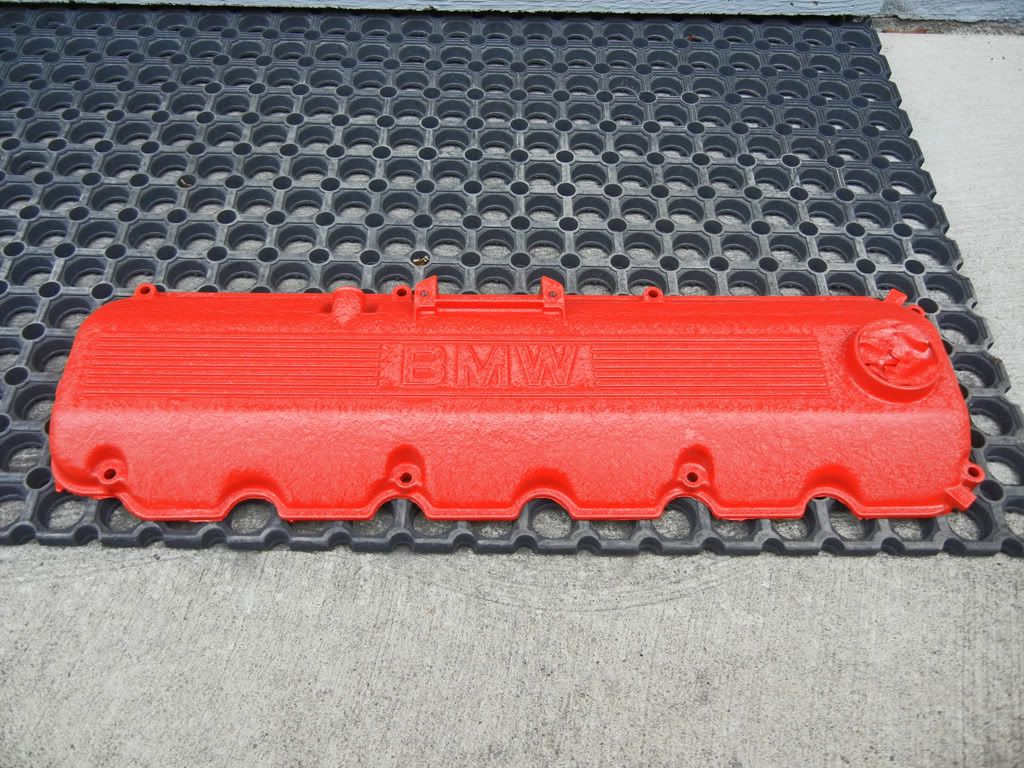
Things are starting to come together, I can't wait to start assembling this thing...
Comment


Comment