If this is your first visit, be sure to
check out the FAQ by clicking the
link above. You may have to register
before you can post: click the register link above to proceed. To start viewing messages,
select the forum that you want to visit from the selection below.
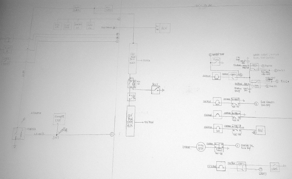
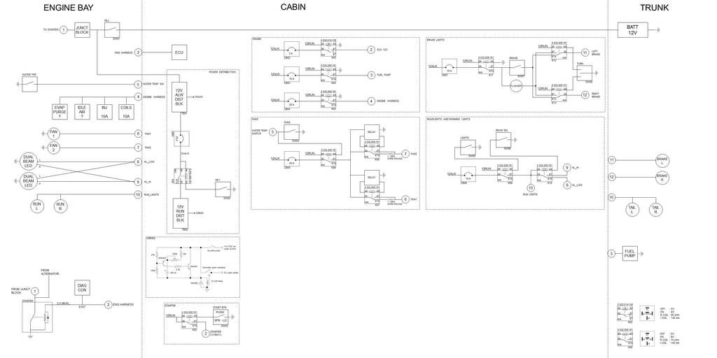
For any electrical geeks out there here is the theory of operation for my dual fan controller with inrush current limiting:
1. Key energizes relay which turns on 12VRUN rail
2. Activating fan toggle or high water temp triggers relay routing 12VALW to fans, also gated by key being on.
3. Normally closed contacts of relays for fan1 and fan2 are routed to 1 ohm, 50 watt wire wound resistors. They are capable of handling up to 10X rated power for 5 seconds. Fans will attempt to pull 50A each (600W) for ~10 ms. They are limited to 12A each by the resistors.
4. When Fan toggle is on or water temp is high, RC delay circuits on each fan relay begin to charge. Fan1 has 500ms delay, fan2 has 1 sec delay. When each delay circuit is fully charged, fan relays switch from current limiting path to direct connect.
Should work .....
"And then we broke the car. Again."Mark Donohue, "The Unfair Advantage"
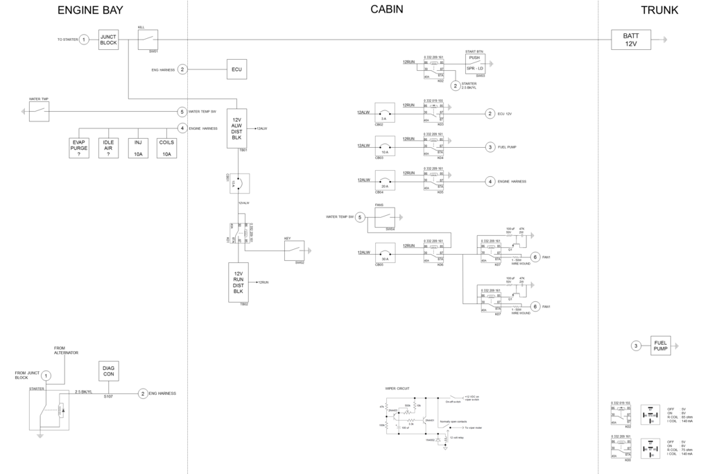
Ha. I guess Varg has not been reading the thread lately or he would have called me out on the last schematic. :devil: Relays coils have low resistance (60 ohms) which would have killed my design.
Here's the new and improved electronic version. Click image for full size pdf.
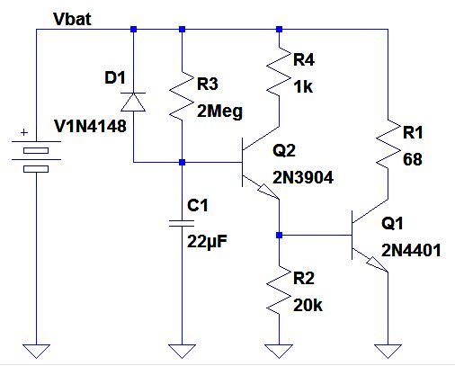
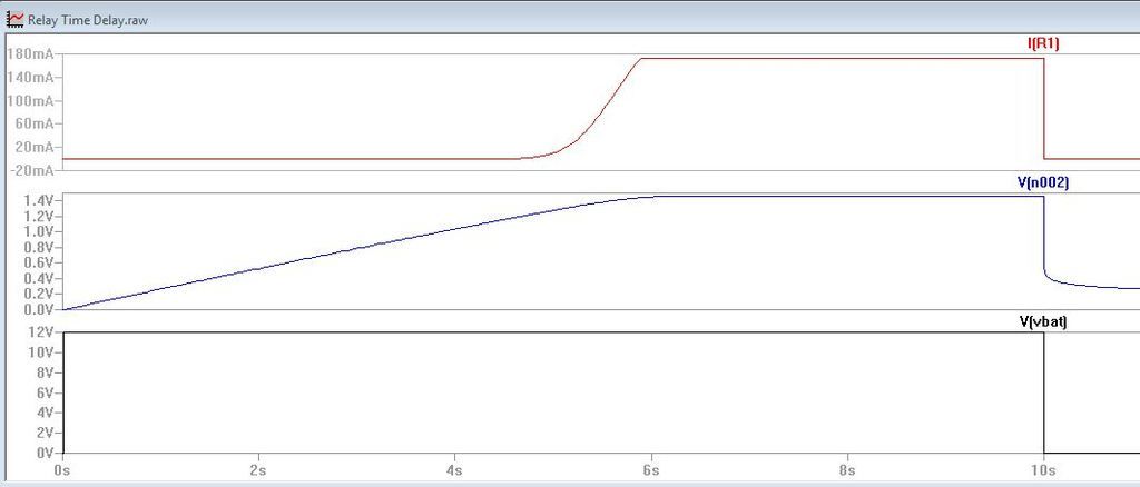
Nothing beats simulation to check an analog idea. Here's the fan inrush limiter delay circuit.
And the simulation. At power-on capacitor C1 starts charging through R3. Voltage on the C1-R3 node increases per the RC time constant as shown in V[n002]. Once RC voltage reaches 1.4V, Q2 starts conducting and Q1 is triggered, allowing current to flow through R1 (simulating relay coil) and close the relay.
Best thing is it doesn't use a honking huge electrolytic capacitor. Just some nice, small axial and through hole components.
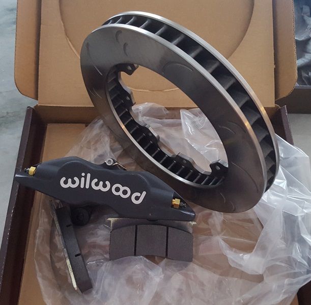
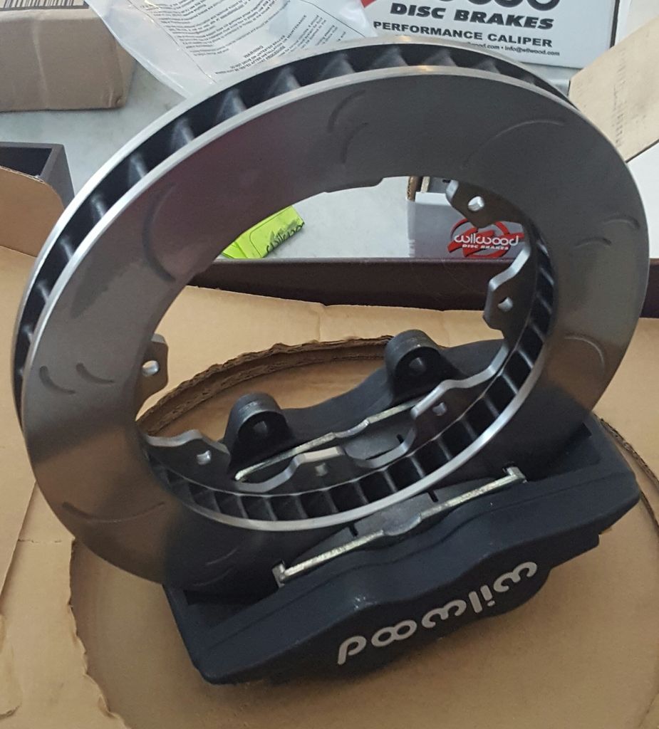
Calipers are Wilwood forged superlite 3.5" lug mount, 4 x 1.625" pistons front (MPN 120-11133), 4 x 1.25" pistons rear (MPN 120-11127). Piston size will give proper front-rear starting brake balance, and can be adjusted further by master cylinder size.
Rotors are enormous compared to stock. Hawk DTC vented slotted directional 11.75" x 1.25" front and rear.(MPN HR8000R x2, HR8000L x2) Primary advantage is large thermal mass to avoid heat soak on the track. Vents also pump air into the rotor, especially in back where there is not much air flow.
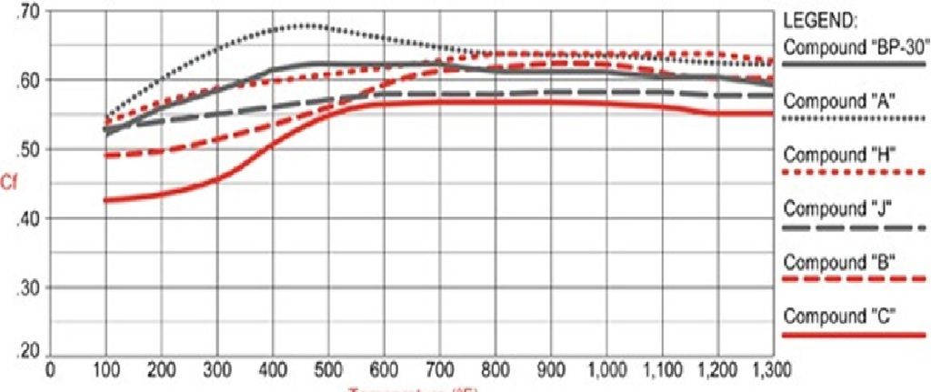
Pads are Wilwood type 7420 poly compound A (MPN 15A-5938K), working temperature 100 to 1300F. In their optimal 300 - 800F range, these things bite with a mu of almost 0.70! Above 800F they drop down to 0.65. Still very good.
All this stuff showed up from Summit today. Wow. In person it is ........ large. Waiting for Lee's bits and pieces to arrive.
150-8854K BP-10, 4.74" x 2.43". Narrow range
150-9416K BP-20, 4.74" x 2.43". Narrow range
15A-5938K POLY-A, 4.74" x 2.43". $160 Better braking at low temps
15B-5939K POLY-B, 4.74" x 2.43". $130 but narrow working range
15C-6853K POLY-C, 4.74" x 2.43". Not available ?
15E-6084K POLY-E, 4.74" x 2.43". $100 but narrow working range
15H-8114K POLY-H, 4.74" x 2.43". $200 Most even across range
"And then we broke the car. Again."Mark Donohue, "The Unfair Advantage"
Just read through this whole thread and thing is gonna be awesome!!!!!
What would the coeficient of friction be for regular stock/street pads? I guess since the rotors are also a bigger diameter there is more leverage and should have some crazy stopping power!!!


Comment