Announcement

Collapse
No announcement yet.

VGT Turbo M20 Sleeper ('87 325 Sedan)

Collapse
X
 
  • Filter
  • Time
  • Show
Clear All
new posts

    #61
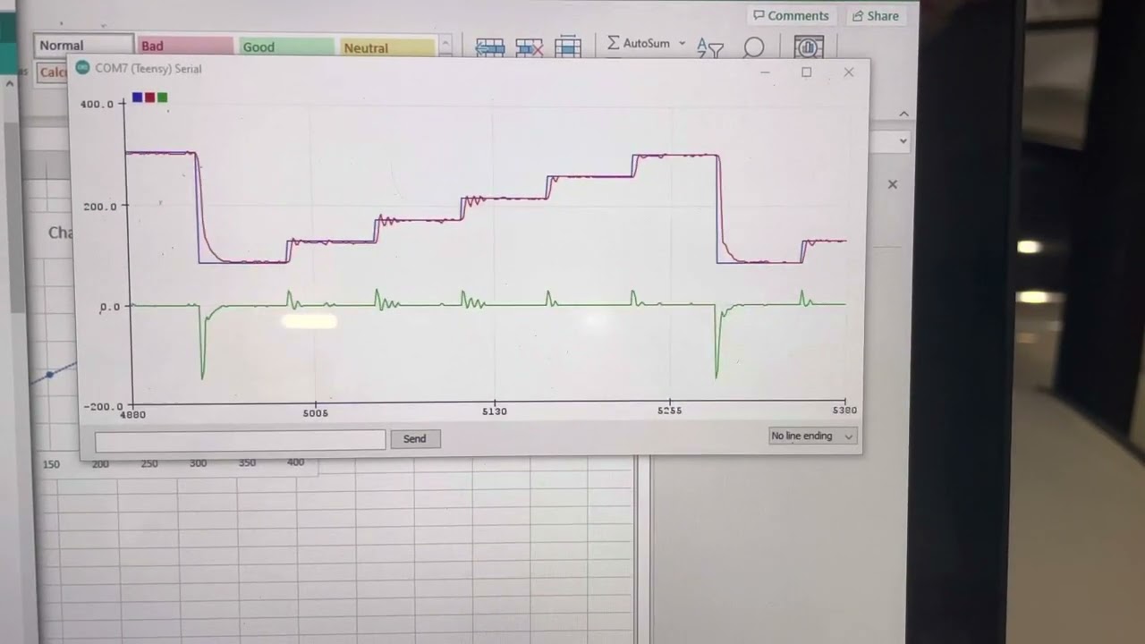
    Here's a quick and dirty model of the VGT response, comparing the previous algorithm to the new one. Qualitatively, it ramps the vanes open as soon as boost starts to build, and opens them fully once the boost target is reached. The old version kept the vanes fully closed until MAP gets to 65% of the boost target, then ramps to full open. So, kind of the opposite approach. There's a lot more nuance than that, but that's the simplest explanation. In practice I think this means I can get more aggressive when I initially close the vanes.

    To add one level of nuance: the "most-closed" vane position is currently engine speed-dependent and has been tuned seat-of-my-pants. I shouldn't close the vanes the same level at 5000rpm that I would at 3000rpm, the flow would obviously choke more at 5000rpm. The concept here is to try to find this choke point empirically: measure things at a specific engine speed like initial boost response rate when going WOT, or monitor AFR, adjust the most-closed position, repeat. There's going to be an ideal "most-closed" position for a given engine speed where the initial boost response is best, and significant choking of the mass flow will show up in AFR. I have a feeling the point of best response is similar to the point where the flow starts to choke. Initial boost response vs. most-closed setting should have a hump shape, need to find the setting that gives us the peak.

    Using the speed-density concept, should be able to then estimate relative mass flow from that initial response level, and map out in two or three dimensions how to open the vanes. Adjust from that calibrated ideal "most closed" point proportionally to engine speed, MAP, and VE (from the fuel table) and that should give a decent starting point for the VGT calibration. There will be a little error since VE table is set to richen the mixture, but heck, I could even correct that out by monitoring AFR. Might have to correct for EGT too. In any case, the math/algorithm is model-based, but model will be calibrated to match the real world as much as possible.

    Example: Hypothetically I measure initial boost response a bunch of times at 3000rpm when MAP = baro (80kPa for me), and find the ideal most-closed nozzle area is 7cm^2. Now I want to calculate most-closed nozzle position at 5000rpm:
    • Let's say VE at 3000rpm is 86%, and at 5000rpm 98%
      • I use that to calculate the most-closed area at 5000rpm: 7cm^2 * (5000rpm / 3000rpm) * (98% / 86%), gives 13.3cm^2
    • As boost rises at 5000rpm, I now adjust my VGT nozzle size position proportional to boost:
      • Let's say I'm now at 130kPa MAP and baro is still 80kPa:
        • 13.3cm^2 * 130kPa / 80kPa gives 21.6cm^2.

    VGT Algorithm analysis by Mikey Antonakakis, on Flickr
    Last edited by mikey.antonakakis; 05-25-2022, 11:59 PM.

    Comment


      #62
      To demonstrate with some real data that the current algorithm isn't ideal, see the following snippet.
      • You can see the vanes (white line bottom plot) stay "most-closed" until MAP (red line top plot) gets 65% of the way to boost target (yellow line top plot). At that point, it starts to open rapidly, marked with first vertical line.
      • A very short time later (second vertical line), the vanes have opened significantly and boost starts to climb more slowly.
      • However, between those two points, boost response is the best out of the whole plot!
      So at the very least, once it starts to open the vanes again, it's WAY too aggressive at opening them. Boost is still rising after then vanes are fully open (hence the need for a wastegate...), but it rises much more slowly.

      boost_flatshift_2022-05-19-2 by Mikey Antonakakis, on Flickr

      Comment


        #63
        After much convolution of thoughts and plans and algorithms I think I have the VGT code (and wastegate dome code) sorted out. Hopefully some testing tonight. Put finalizing the touchscreen OBC board/controller on hold so I could finish the VGT code, I wanna drive the car!

        Comment


          #64
          Oh and Ground Control coilover conversion and Koni sports are on their way, and I’ve got a Z3 rack waiting for my Garagistic order to ship… (ordered 3 weeks ago, but seems like the delrin steering flex disc was backlogged). Finally replacing the last of the original suspension! (Well, still need swaybars…).

          I think the shocks may be original and the rack in the car now is worn causing play between the front wheels despite brand new tie rods, control arms, strut mounts, etc. It will be nice to have non-sloppy steering for the first time ever with this car! I might even wash it for the first time in, I don’t know, 9 years? Gotta be frugal with the washes, the clearcoat is long gone and you can wipe the powdery paint off the car with your finger!

          Comment


            #65
            Finally got the test drive in! There are a few bugs in the code, but I was able to sort some of them while driving. For instance, I’m using VE in part of my algorithm, assumed MS sent as 0.96 rather than 96%, which threw the math off by a huge amount. Easy fix that got the new VGT algorithm functioning on a basic level.

            There are still a few issues, for example I offset the boost target a little before I include it in the VGT algorithm in order to ensure the vanes open fully at full boost - the new algorithm is a little too harsh with this at low rpm, though. The vanes snap fully open and cause boost to drop, so the vanes close, a nice oscillation.

            I ran this whole session on wastegate-only, with a lighter spring. Getting me 135kPa MAP for full boost (“5psi” if I was at sea level). Even at this low boost the car is quick, absolutely shredded the tires on a first-gear rolling 2-step launch test (2.93 diff).

            Dome pressure control PID code is working well in the garage at this point. The version rolled into the full display/VGT code must have some critical bug though. I made that section of the software switchable (enable or disable it), and enabling it caused the microcontroller to lock up, so I’ll have to see what that’s about… I have a feeling I know what’s going on, will look into it tomorrow.

            Anyway, the VGT algorithm overall seems to work really well. For the purpose of running on wastegate-only (to measure wastegate-only boost level for the dome pressure control) I disabled the “keep the wastegate slammed shut during spool” feature, and from experience that means I wasn’t spooling as hard as I could be. With hardly any VGT tuning it already seems to spool faster, especially at lower engine speeds. Like, 1800rpm I can make a couple psi in a few seconds. 3000rpm I get to 3psi in about 1.5 seconds before the spool really takes off. The code is a lot more manageable now, a lot easier to change settings quickly for comparison.

            Going to iron out some of the bugs/imperfections this weekend and get some data to compare old vs. new algorithms.

            Comment


              #66
              Another test drive tonight. Majority of bugs are fixed, will probably still make some refinements to parts of the algorithm. Overall though it is working smoothly and predictably, needs more tuning.

              Facing one major frustration right now - boost solenoid inconsistency. It’s super important to get a good characterization of the solenoid open threshold (how much PWM to get it to start to crack open). On a 0-255 PWM signal range, it varied anywhere from 55 to 95 tonight for my fill solenoid. Vent solenoid was a little more consistent, but still problematic. This variation throws off the PID controller a huge amount. As I type this it’s just occurred to me that maybe I am being too aggressive with PWM frequency, currently set to 70Hz. Maybe too much dead time for that. Will try 20-40Hz tomorrow to see if that makes them more consistent.

              Comment


                #67
                Did some refinements to VGT algorithm, basically adding more adjustability. Have an occasional wild fluctuation at/near full boost where the algorithm closes the VGT a ton for some reason. Should be straightforward to figure it out.

                Dome control solenoids are behaving a lot better at lower PWM frequencies, but by necessity I need to run the PID loop at a lower frequency as well, which gives a little more fluctuation. I at least got it fairly stable and repeatable, but there is a decent amount of error that doesn't entirely make sense to me. Like in the data below:
                • before and during spool-up, I keep the dome pressure high to keep the wastegate seated.
                • Then as I approach my target boost, I drop the dome target to the value that will net my boost target - in this case, 25kPa above barometric (105kPa absolute).
                • The solenoid control at that point is commanding between -23 and -30, which means the fill valve should be fully shut and the vent valve should be venting a decent amount.
                  • All it has to vent in this instance is the volume of air in the wastegate dome and a few inches of 1/4" OD hose.
                  • Despite that constant vent command which should totally and immediately shut the fill valve and vent the wastegate dome to atmosphere (confirmed in testing at engine idle/engine off), my dome pressure is staying at 140-145kPa absolute.
                  • So either:
                    • The fill valve isn't shutting fully due to mechanical issue or incorrect command signal (should cause compressor in trunk to run a lot more often than it was, so I don't think it's this)
                    • The vent valve isn't venting due to mechanical issue or incorrect command signal
                    • Boost is leaking past the wastegate seals? It would have to be a big leak to overpower the vent solenoid if it's working properly
                In addition to that, the opposite condition is also happening - I am undershooting in both directions despite a constant command to either fill or vent the dome. Prior to reaching the boost target in the log below, my dome target is 315kPa absolute and actual is 278kPa absolute, and the command is +26. This command value should fully shut the vent and open the fill a decent amount, which should very quickly bring me up to source pressure (~355kPa absolute).

                One of the things I can also try is to change the plumbing for the vent solenoid. Currently fill solenoid is normally closed and vent is normally open (when not energized), ensuring the dome pressure stays at atmospheric if there's a wiring failure or something. But looking at diagrams from Holley or others, it looks like often they run both valves normally closed. This inverts the required signal at the threshold of opening/closing the vent solenoid, maybe the vent solenoid will be happier running normally closed. I have overboost protection turned on permanently, so not too much of an issue if something goes wrong.

                vent_not_venting_2022-05-30 by Mikey Antonakakis, on Flickr
                Last edited by mikey.antonakakis; 05-30-2022, 09:10 AM.

                Comment


                  #68
                  Originally posted by mikey.antonakakis View Post
                  In addition to that, the opposite condition is also happening - I am undershooting in both directions despite a constant command to either fill or vent the dome.
                  Could it be Stiction in the valve? Possibly present at temperature but not when the engine is off?

                  Comment


                    #69
                    Originally posted by Panici View Post
                    Could it be Stiction in the valve? Possibly present at temperature but not when the engine is off?
                    Could be... although I let the car idle for 30+ min and as soon as I started driving and actually included any engine speed/turbo compressor, it started acting up a bit. My "bench tuning" at idle prior to this wasn't 100% repeatable either. I've got some more investigation to do.
                    A related point: I'm using a JGS wastegate (JGS400 v-band). Nicely made unit, piston-style actuator rather than diaphragm. The piston area is only slightly larger than wastegate valve area, different than many external gates that have a large-diameter diaphragm. This means the boost level is more sensitive to turbine pressure. This probably explains why my 130kPa (absolute) base boost with 65kPa (gauge) on the dome only gave me about 165kPa MAP (basic idea of dome control, that dome pressure adds to spring pressure, says I should have been at 195kPa MAP in this condition).

                    Comment


                      #70
                      Dome control is close! Changed up the plumbing a bit - vent solenoid changed from normally open to normally closed. Pressure sensor moved from the tee at the solenoids to the dome directly (had to drill/tap another port in the dome). PID is a little slow, needs more tuning, but it's stable and hitting its targets. Need to add a little more hysteresis to prevent the boost fluctuations seen. This is due to the "boost = spring pressure + dome pressure" not being totally true combined with the slow PID operation in this log. Also my dome pressure sensor is not calibrated well (will do a good calibration on it this evening).

                      dome_control_almost_2022-05-31 by Mikey Antonakakis, on Flickr

                      Comment


                        #71
                        Some details on the solenoid plumbing modifications:

                        Here are the solenoids as set up previously, nevermind the ugly mount. Eventually they'll get something nicer. Lefthand solenoid is fill (with hose going back to compressor in the trunk), the other is vent - vent solenoid was purchased 10+ years ago from DIYAutotune (knockoff Humphrey 310 I think?), fill (genuine MAC valve, or a believable knock-off) was a more recent purchase. I've got another matching MAC valve arriving soon to replace the fill. The lower brass tee fitting splits the solenoids' output - one side goes to wastegate dome, other side is the pressure sensor.

                        20220531_115122 by Mikey Antonakakis, on Flickr


                        The changes were twofold: move pressure sensor directly to the dome to get the most accurate signal and maybe to dampen the pressure fluctuations from the low-frequency solenoid PWM operation (the solenoid valves bounce between full open and full close, they don't "float"). This is how Holley recommends to set things up, for what it's worth. My JGS wastegate only has one port on each side of the piston, so I had to drill and tap another, 1/8" NPT. Other main change: re-plumb the vent solenoid to work as normally-closed instead of normally-open. Less iditot-proof this way, but again it's how Holley recommends it. Also means that the transition from blocked to venting happens at a low duty cycle now. Maybe these valves are happier running that way? Sure seemed like it from the test results.

                        20220531_113757 by Mikey Antonakakis, on Flickr

                        20220531_115918 by Mikey Antonakakis, on Flickr


                        Back together, pressure sensor relocated a bit and vent solenoid converted:

                        20220531_133917 by Mikey Antonakakis, on Flickr

                        Comment


                          #72
                          Old DIYAutoTune solenoid replaced with another MAC valve, this time with no filter on the vent port. It tuned in really nicely in some quick bench testing tonight with engine off! Higher voltage with the engine running at cruising speed may shift my deadbands a little, but that's easy to recalibrate for at this point. The PID tuning is getting close to dialed into where I want it, as shown in the video below.

                          I also calibrated the dome pressure sensor to the Megasquirt's MAP sensor. Happens to be that 10-bit ADC counts are very close to being the same as kPa, and very very linear. I'll still need to add a correction factor into the code to account for the exhaust manifold pressure on the wastegate valve - basically need to just shift dome pressure target to be about 20kPa higher than the math would suggest.

                          Untitled by Mikey Antonakakis, on Flickr

                          Comment


                            #73
                            Love the plot video, nothing like some live data to start the morning!
                            Interested to see if the new valve makes a noticeable difference when driving.

                            Comment


                              #74
                              PID is definitely snappier than the last drive, so that should help with the overboost. Once I update the dome target math to include that real-world offset from “target boost - spring boost” I think it’ll be working pretty well!

                              Comment


                                #75
                                Made a major addition to the dome control algorithm today: a lookup table of steady-state target MAP vs. dome pressure. This replaces the idea that dome pressure target should be boost target minus spring-only boost, which is not a great model for a real wastegate. This makes the dome control basically one or two steps less advanced than the most fancy options out there, and should work really well. Easy to add the last step or two: add RPM dependency to that look-up table as well (not a huge influence), and go to true MAP target PID control, with outer PID loop monitoring MAP error to determine target dome pressure, and inner loop making sure the dome control meets that target pressure.

                                With the current state of things, the pure dome control PID is working pretty well at this point and just needs a little fine tuning with real driving. A quick test drive this afternoon identified two bugs causing some crazy operation of dome target and VGT, both should be fixed now.

                                First datalog shows a fixed dome pressure control, with a target dome pressure of 105kPa all the time. The dome control is pretty good here, but in this log you can see the major VGT bug: as soon as MAP hits the boost target, the VGT closes fully. Had a small mistake in one line of code that does some math to taper the VGT position to fully open just before the engine hits target boost. It caused a crazy position command to fully closed once target boost was reached. This in turn probably caused huge exhaust manifold pressure that pushed the wastegate open, increasing dome pressure. The dome pressure control actually handled this crazy condition pretty well:

                                VGT_glitch_at_full_boost by Mikey Antonakakis, on Flickr


                                Next datalog shows pretty stable operation of the VGT, but a major issue with the dome target. This time it's using the new lookup table to determine dome target. Very simple user input error here caused dome pressure target to be 13kPa absolute lol. The dome PID did what it could, but obviously can't get it down below barometric pressure (80kPa). So here we are seeing the boost level at wastegate spring only. Dome control PID settings are a little too agressive, hence the brief oscillation on step changes in target. But it's close!

                                dome_control_glitch_2022-06-02 by Mikey Antonakakis, on Flickr

                                Comment

                                Working...
                                X