
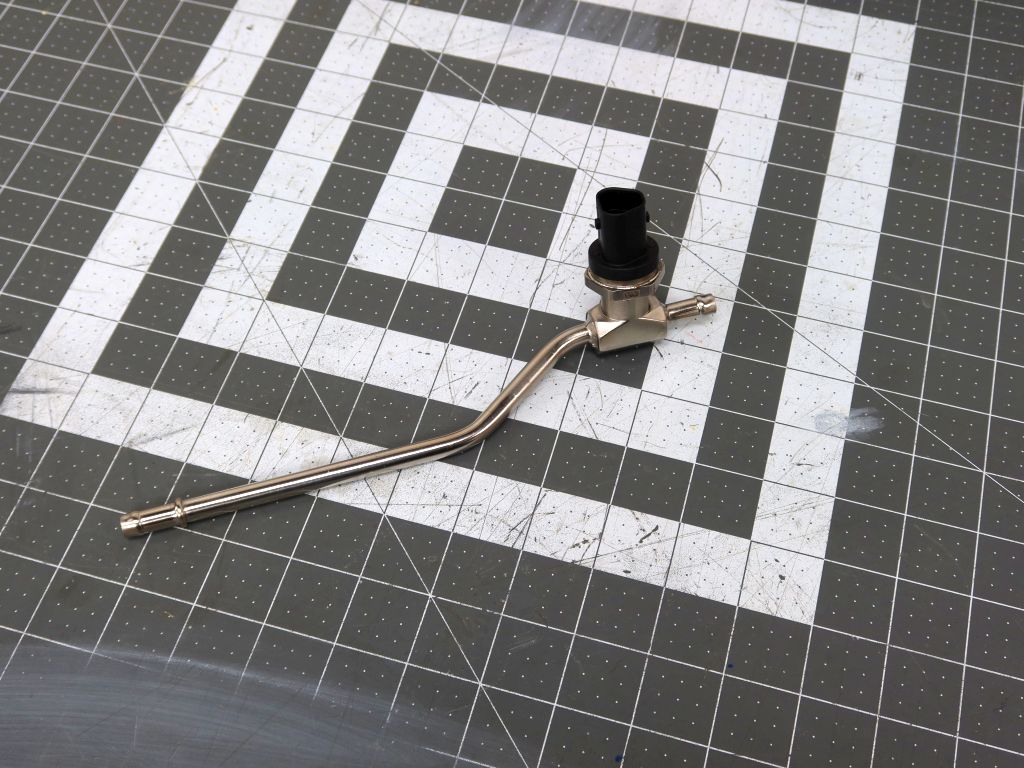
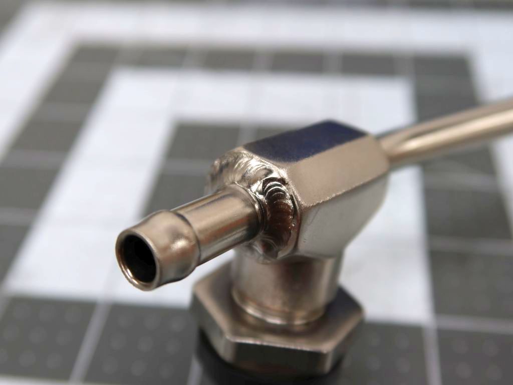
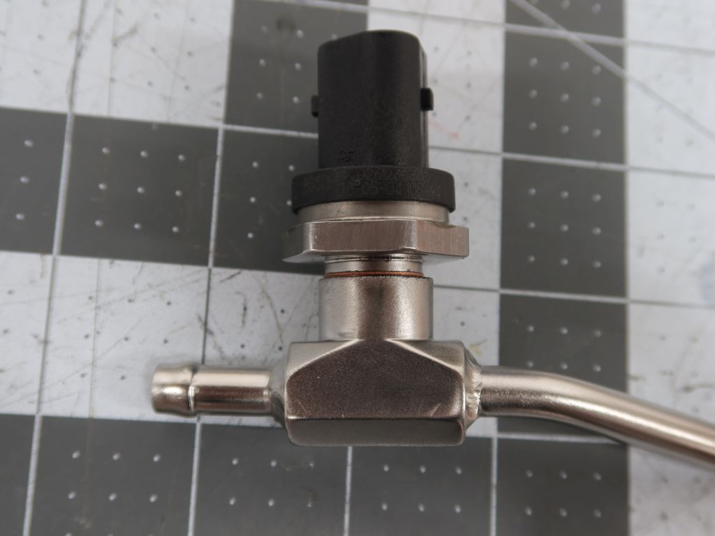
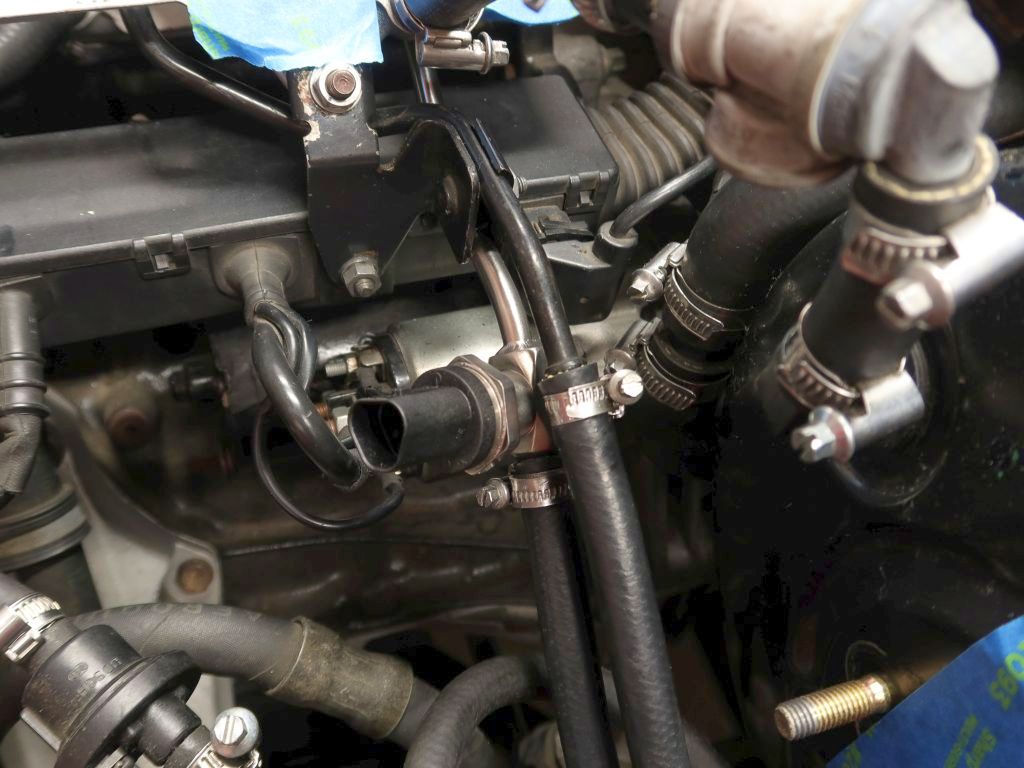
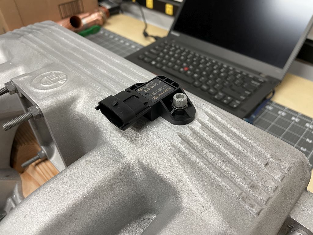
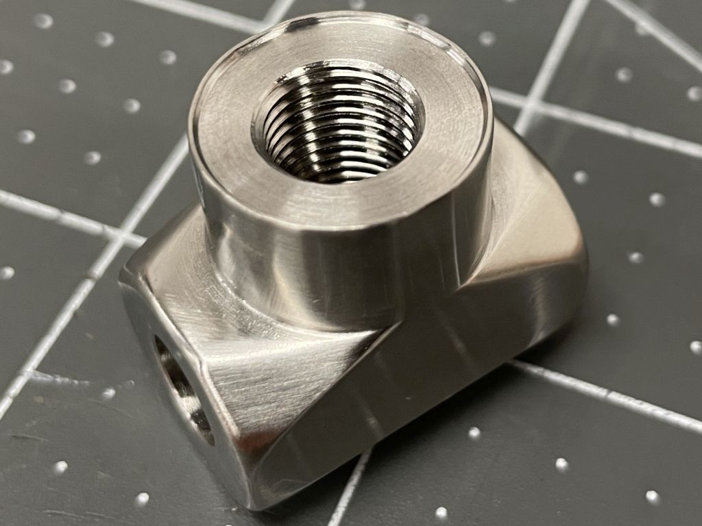
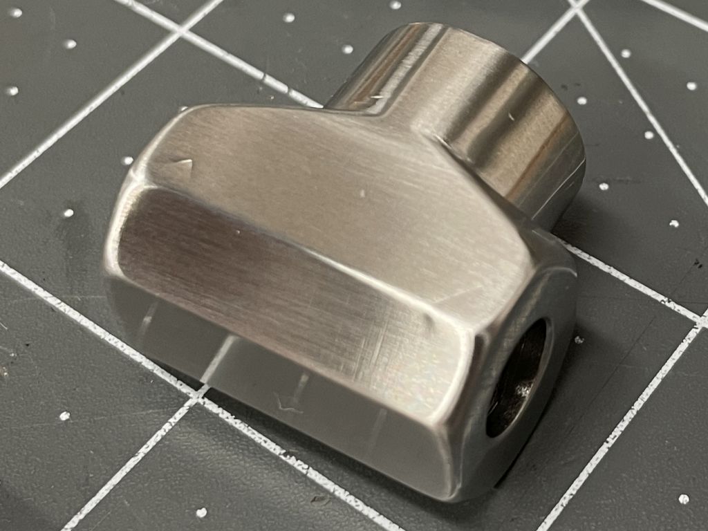
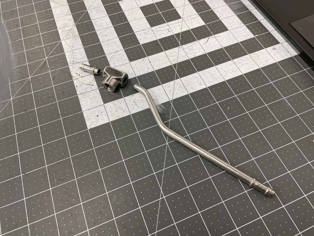
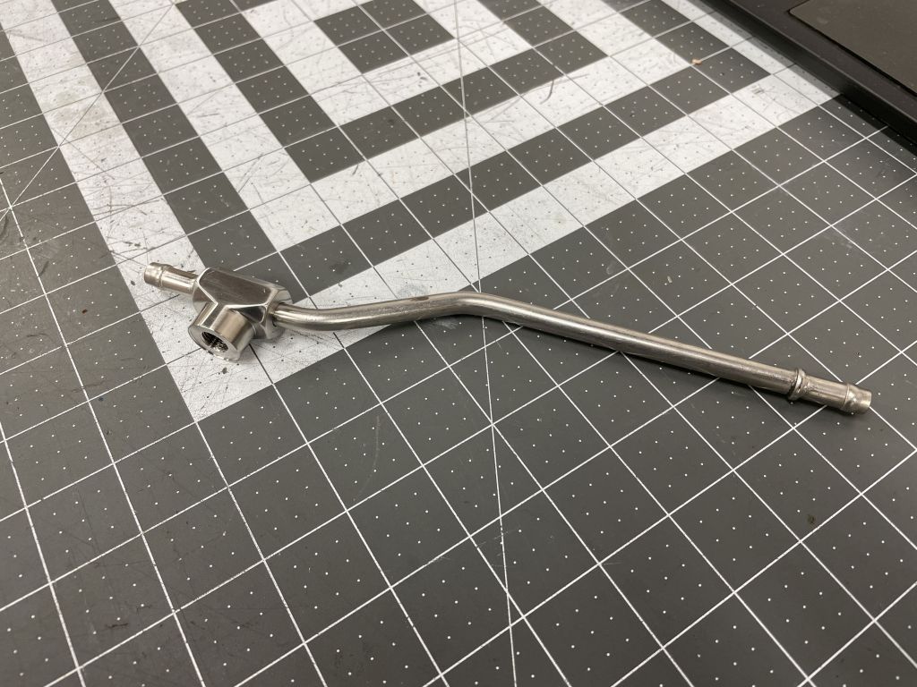
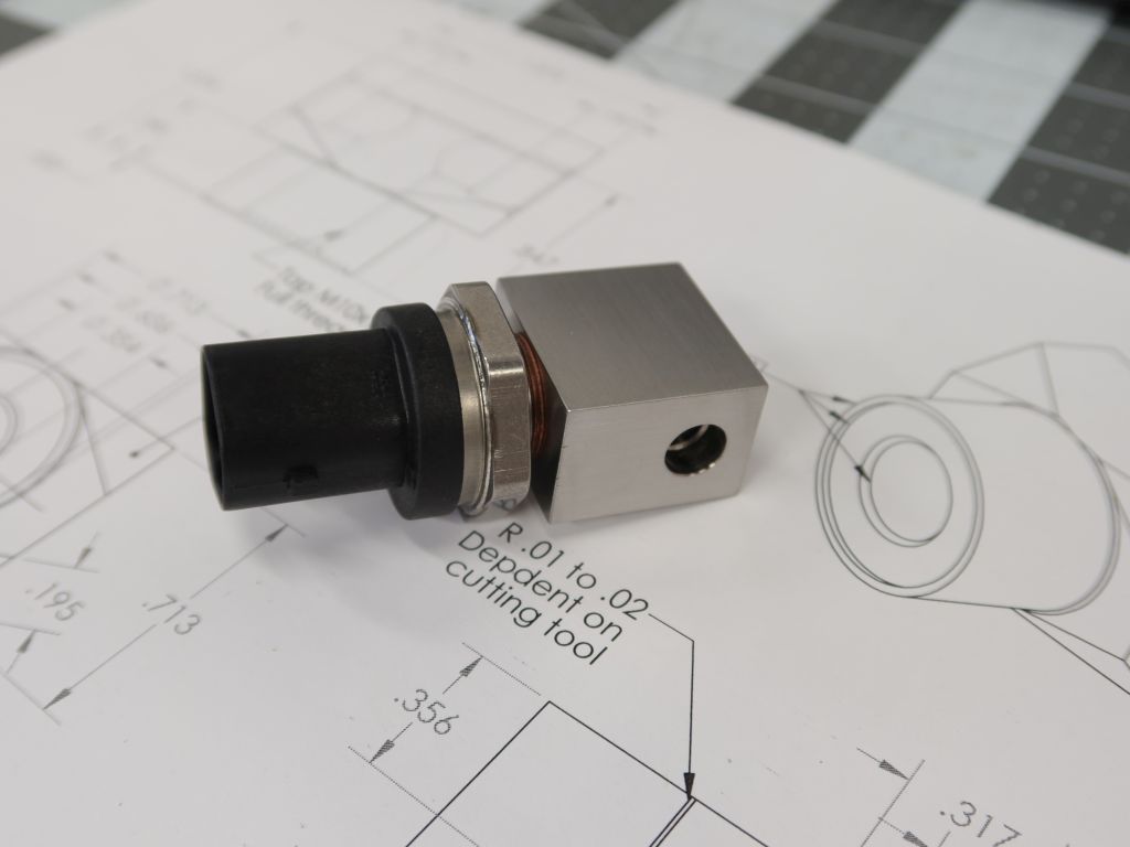
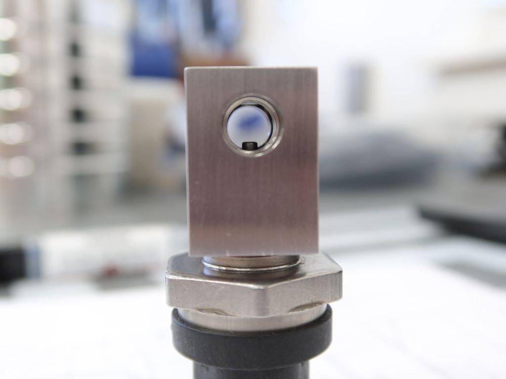
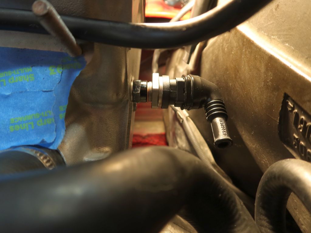
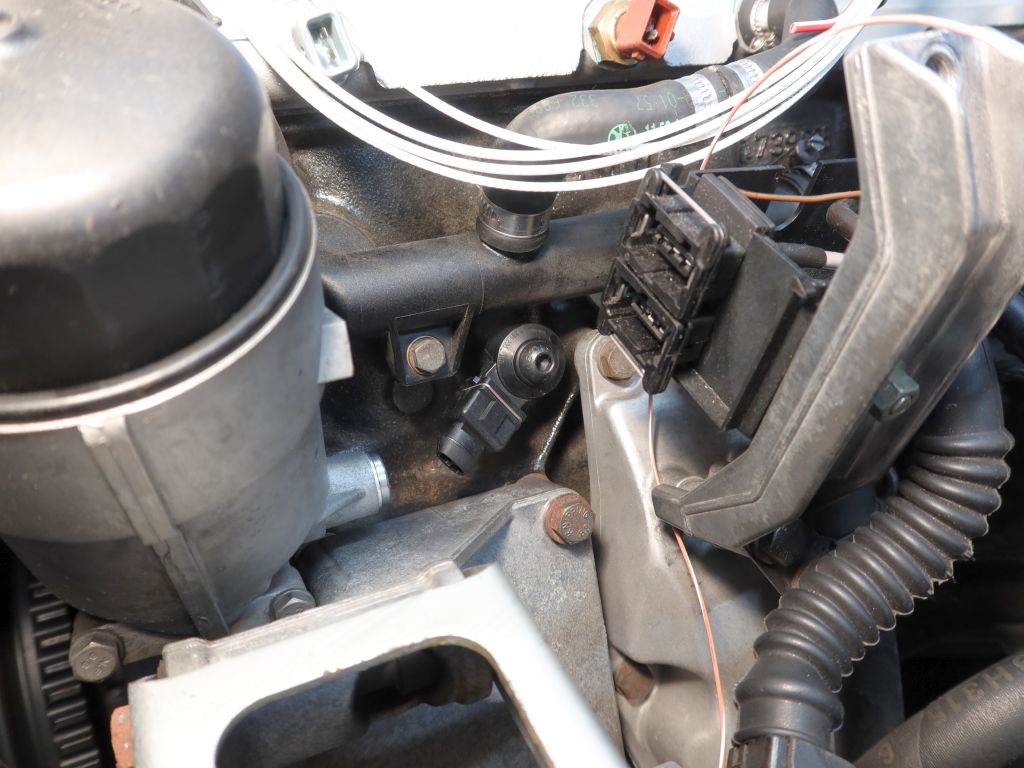
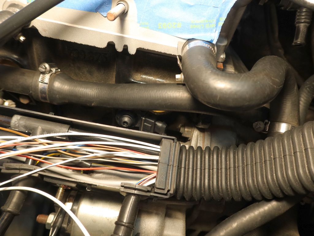
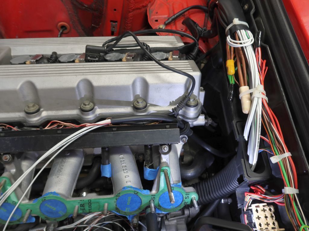
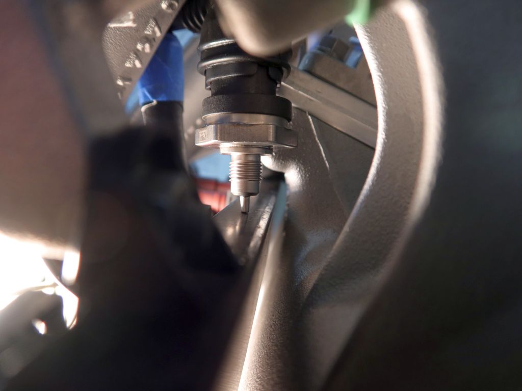
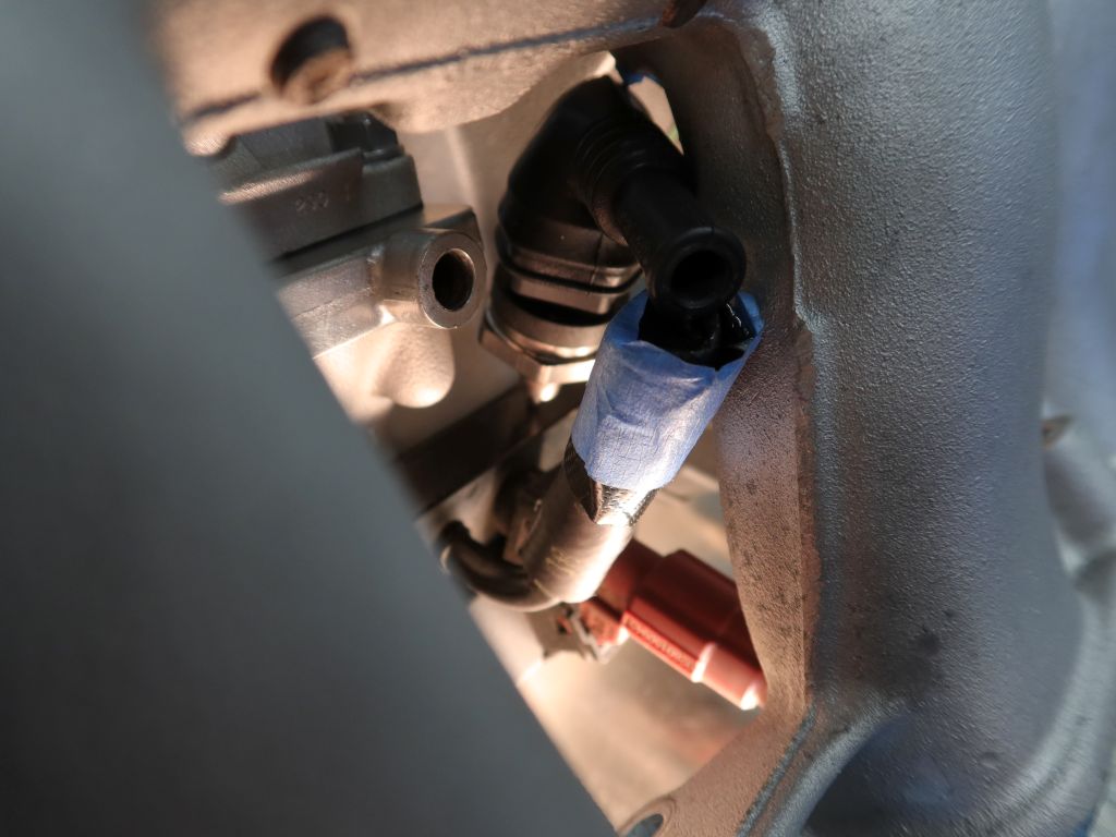
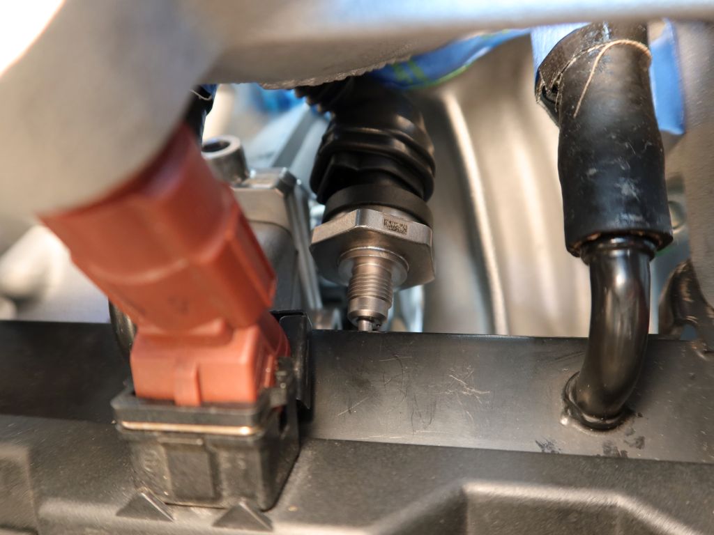
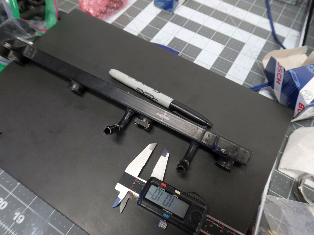
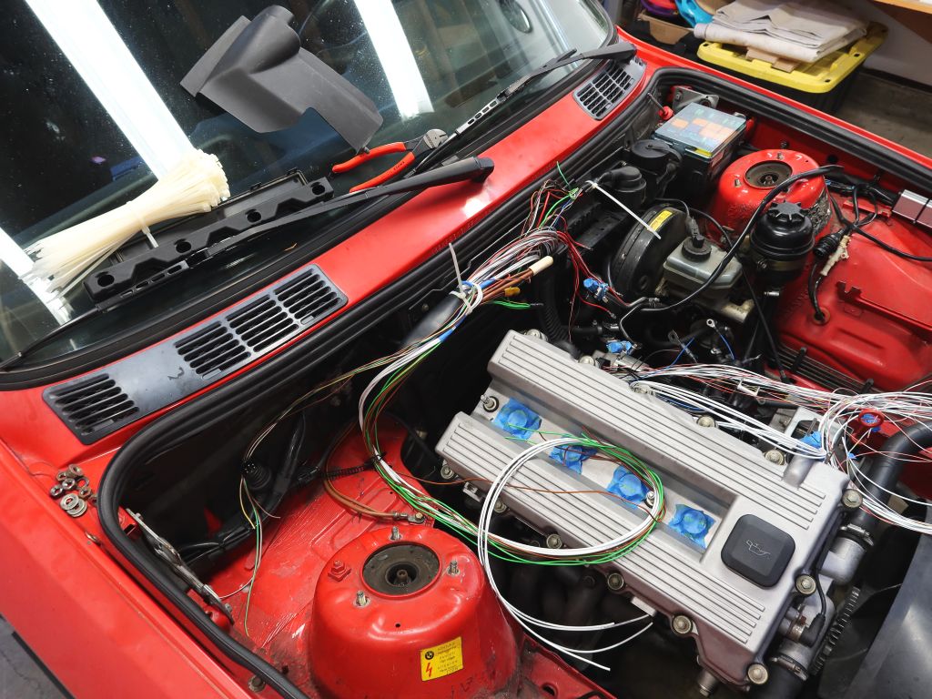
I had a local guy TIG the fuel tee together and it came out looking very good. I have it a quick whack with a fine wire wheel to get it all to a uniform color and installed it. The sensor is installed with 40Nm (30ft-lb) per the datasheet. While I was in there I replaced all of the fuel soft-lines under the hood, and I am going to do the ones at the rear of the car in the near future. other than that, I just need to install the sensor for the oil into the back of the head. For now I am going to put things back together and keep running on stock engine management, probably until closer to Christmas when I will have more of a chunk of time to dedicate to bring-up with the new system.
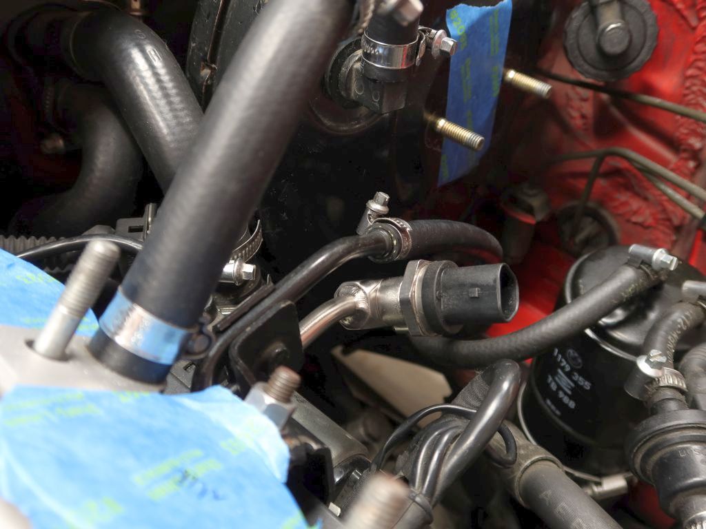
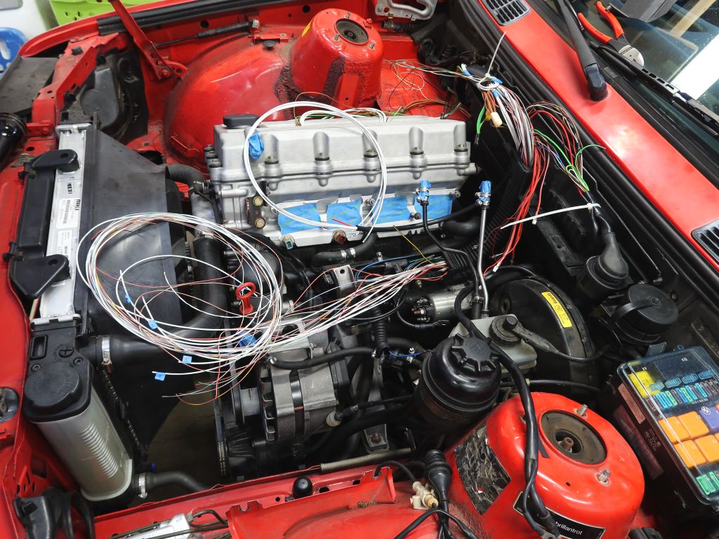
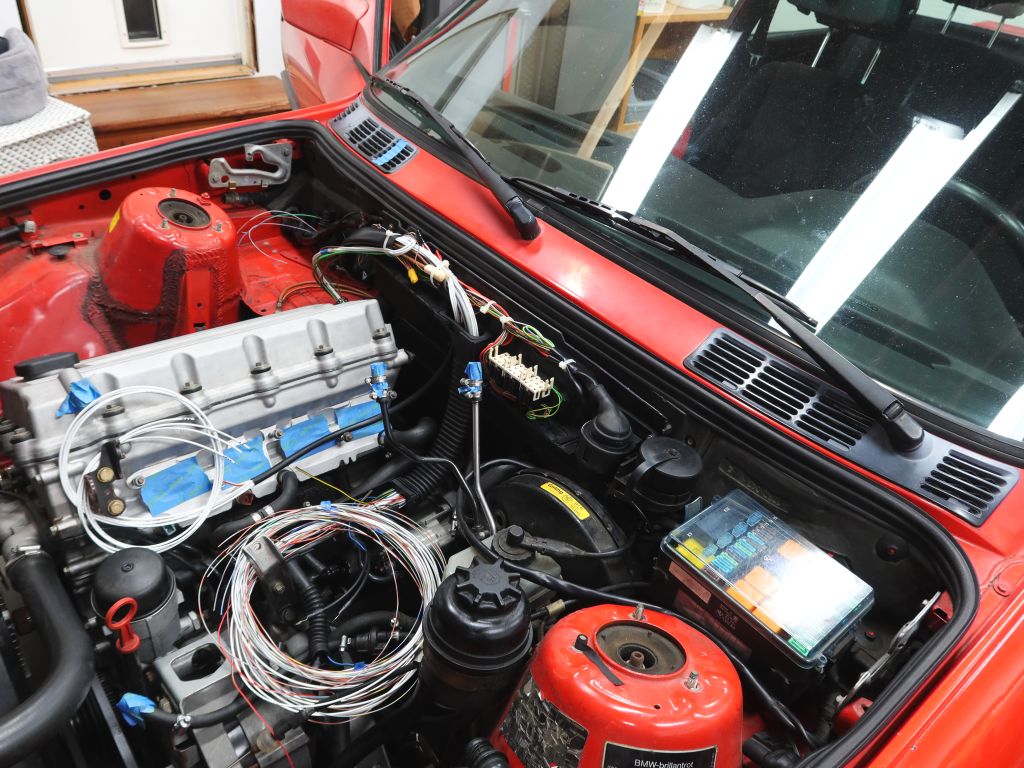
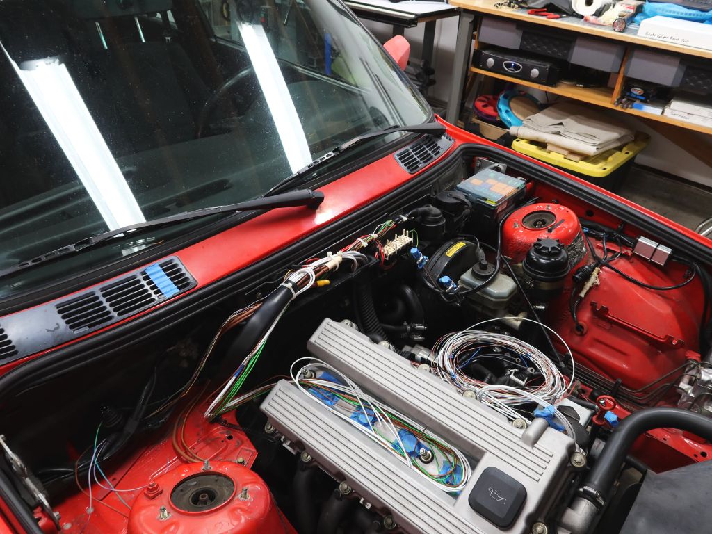
For now though, here's how the fuel stuff turned out. It almost looks OEM!


Leave a comment: