If this is your first visit, be sure to
check out the FAQ by clicking the
link above. You may have to register
before you can post: click the register link above to proceed. To start viewing messages,
select the forum that you want to visit from the selection below.
Yeah, the thought to stick the dies on a mill and hog out the little protrusion crossed my mind. Not sure if it is worth it since I am "only" crimping ~120 terminals lol.
I am sure that there are cheap ratcheting crimpers out there that have the circular profile in the cable grip area, maybe I need to dig around Amazon a bit more.
Otherwise, I guess I will get some grip strength training!
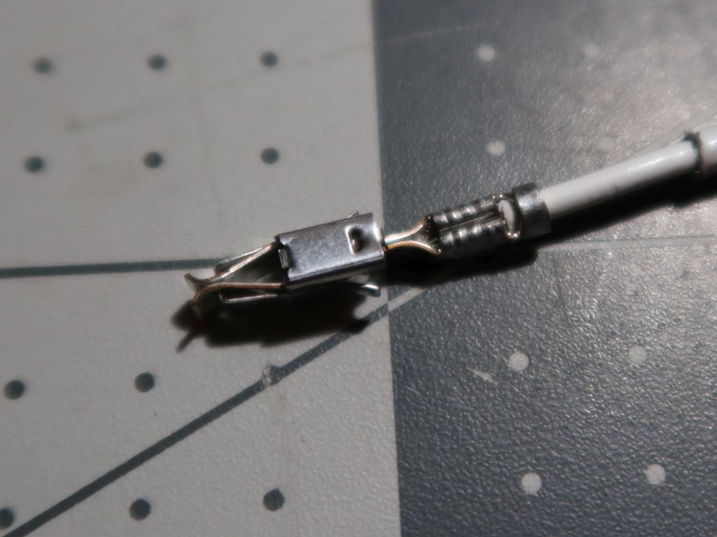
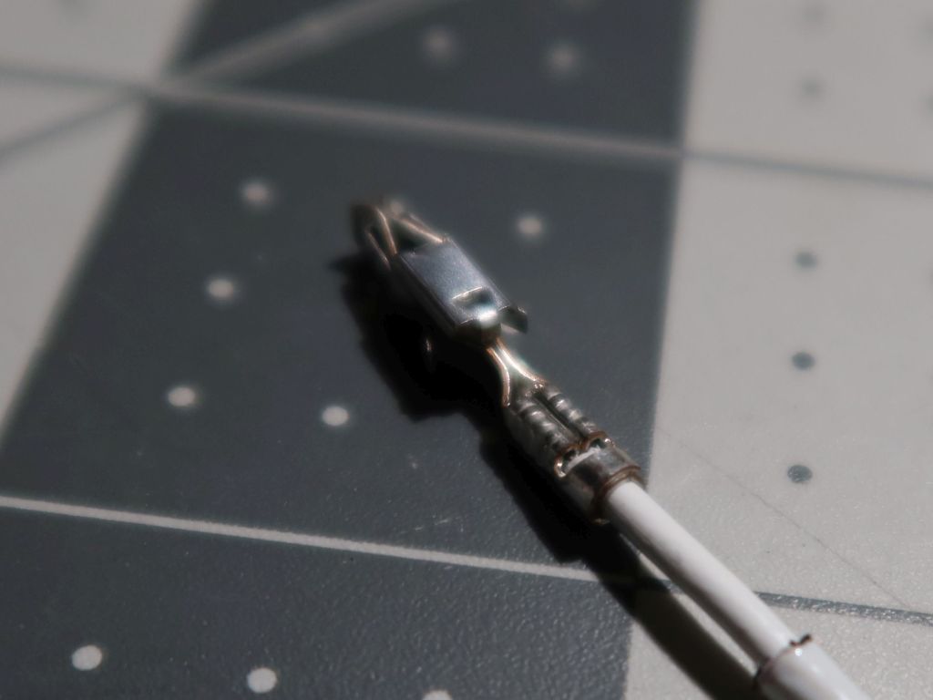
I really wish I could use the ratcheting ones since they are a lot easier on my hands, but none of them deal with the cable grip portion properly. They all drive the wings straight into the cable and tear up the insulation. So, that leaves me with some non-ratcheting ones which can do the grip & conductor sections separately. The crimps produced by them are, in my opinion, as good as they are going to get without the VERY expensive TE-brand crimp tools (sorry, not gonna drop $1600 for the tool bodies & dies to be able to do MT1, JPT & SPT terminals). I inspected all of them under my microscope and they look like they will be more than adequate to ensure good electrical contact & a clean hold on the insulation.
Any chance that one of the ratcheting crimper dies could be modified so that it doesn't arc the strain relief tabs so tightly? Basically grinding that section from the sideways "8" shape into a larger radius "O"?
Surprised there isn't something that exists for the ratcheting crimpers already
Small updates. Since the last post I started a new job, and I have been pretty focused on that as well as some badly needed home renovations. However, this project has not been forgotten, and I am going to start plugging away at it again when I have some time here and there. Basically, I need to deal with some of the custom machined parts for sensor adaptation, and I need to remove the existing wire harness from the engine so that I can properly size everything with the new harness dry-fitted. The harness is about as complete as it can get while not being installed in the car. Luckily, the M42 harness is easy to swap around, and the only headache is removal of the intake manifold (95% sure I cannot just shimmy the wiring box out from under it). I think that I can probably swap in this work-in-progress harness and get everything at the ECU connector side adjusted to the exact right length, and then put back the stock harness in a single weekend.
This weekend I worked on a couple of things.
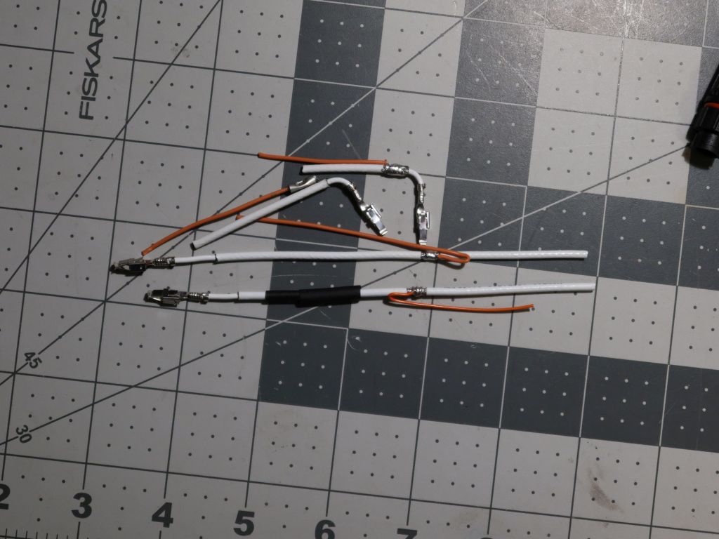
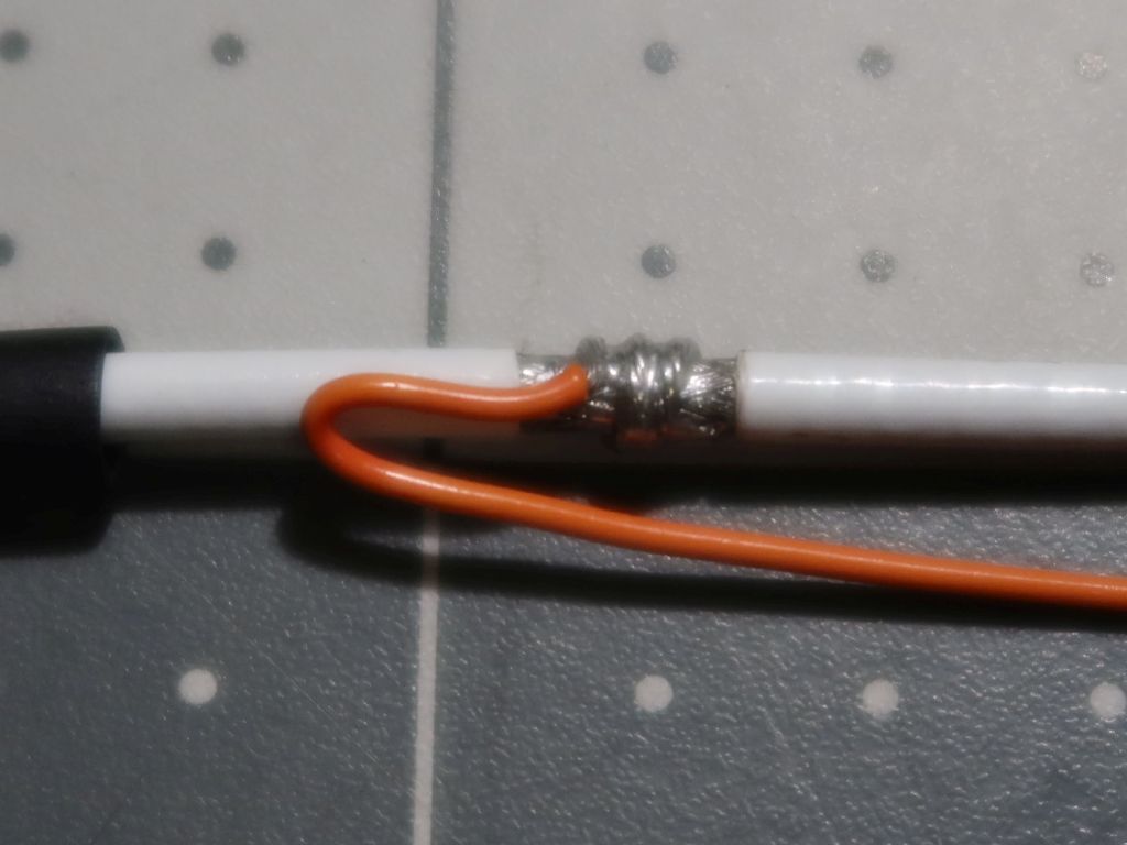
Item 1 was finalizing my strategy for dealing with the shielded cables, specifically in how I will terminate the shields. I had posted some ideas about this earlier in the thread, but I looked back over the NASA workmanship guidelines for harnesses and saw a better solution than trying to terminate things at the end near the connector terminals. The ignition coils' switched primary lines in particular demand care in this area since they see ~425V spikes each time a coil fires, and I do not want any arcing due to damaged insulation or pokey-bits near the terminals.
Here is a little pile of "experiments" I got some practice with.
The "aha" moment I had was when I decided that it made a LOT more sense to lash the termination wire onto the shield braid a lot further from the end of the cable. It has a couple of benefits. One is that it doesn't put any risk of a stiff soldered mess of shielding right where the wire will have a sharp bend for the terminal to install in the carrier. The other benefit is that I can do this termination a couple of inches outside of the connector housing entirely; things in there are going to be cramped, and not having the extra wires, solder joints and shrink tubing inside the housing makes life a lot more pleasant. Another change is that I will just use 24ga wire for this. Previously I was taking 20ga wire and trimming off all but 4 strands of the conductors in order to make the lashing manageable. 24ga can be used as-is without hacking it up, and since the termination runs will be at MOST 6", probably more like 3", the smaller conductor size won't really matter.
I also used up several extra terminals to get my crimping game dialed in. I have several generic crimp tools for this category of terminals, but none of them are specific to TE Timer-series terminals. I really wish I could use the ratcheting ones since they are a lot easier on my hands, but none of them deal with the cable grip portion properly. They all drive the wings straight into the cable and tear up the insulation. So, that leaves me with some non-ratcheting ones which can do the grip & conductor sections separately. The crimps produced by them are, in my opinion, as good as they are going to get without the VERY expensive TE-brand crimp tools (sorry, not gonna drop $1600 for the tool bodies & dies to be able to do MT1, JPT & SPT terminals). I inspected all of them under my microscope and they look like they will be more than adequate to ensure good electrical contact & a clean hold on the insulation.
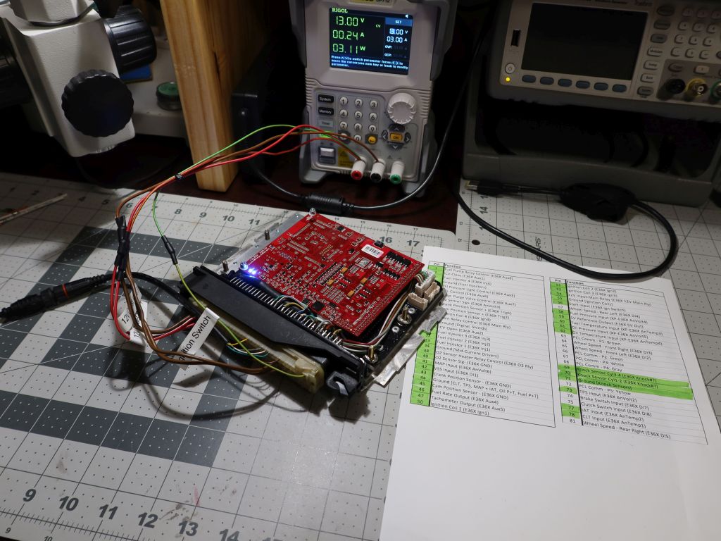
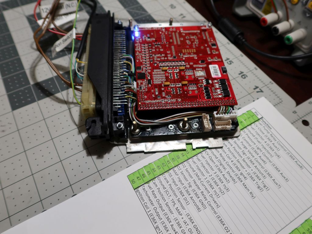
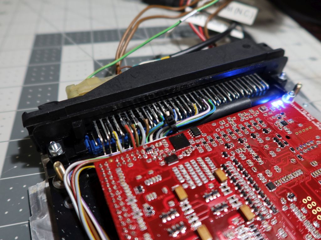
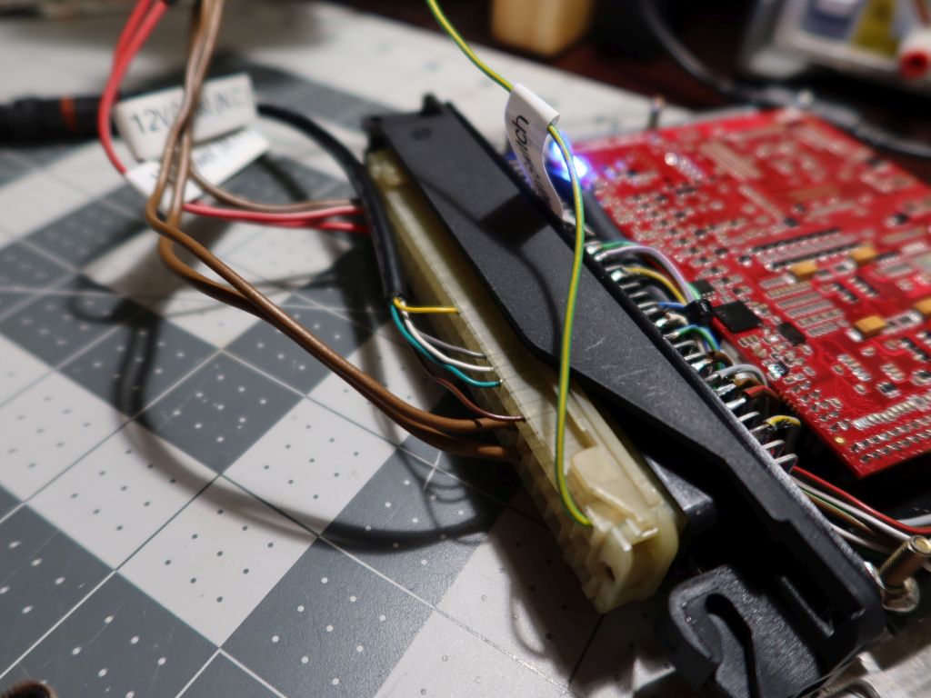
Item 2 for the weekend was implementing the little customizations on the E36X ECU itself. I want all connections made through the 88 pin connector. It doesn't really matter for any practical reason, but I like the simplicity of having a single point of connection. It would be trickier if I was using the built-in MAP sensor since there's no way to run a vacuum line through the factory connector, but since I am installing a MAP sensor directly into the intake manifold all I need is wires. With all of the sensors I am adding to the engine, I needed to use all of the extra analog & digital lines on the internal expansion connector. None of those connector terminals were internally routed to the 88 pin connector, so I made a little mini harness and soldered the wires directly to several unused pins on the output connector. Also, I want to have the USB interface cable fully integrated into the rest of the harness, so I did some similar hacking to put all of its connections onto unused pins. It works just fine and there are no communication issues with it set up this way. I guess we'll see how it goes when the car is running and the ignition is firing since the ignition leads are going to be right there next to things.
I am also going to start poking through the PCLink software interface more. There is a LOT of capability here! Since my last post, Link has released about a dozen firmware updates with fixes and features. It is great to see that they support their product so well (it helps that the E36X is based on the G4X which is their current generation product).
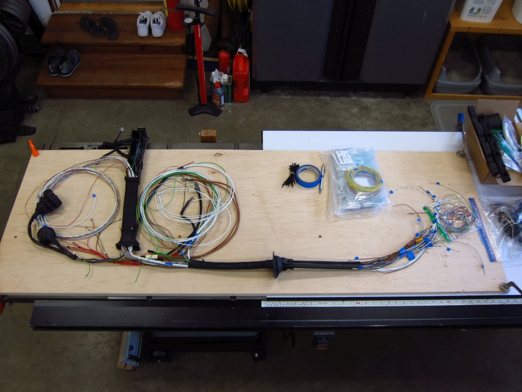
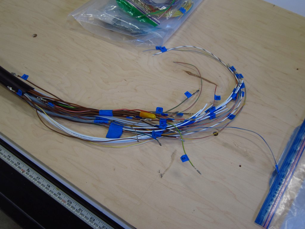
I am still not 100% back to working on this since I have told myself that I will finally deal with the full repaint this fall, but in the interim I have a little time to poke at the ECU project and do some basic legwork. As such, I finally planned out the wire arrangement for the main run that goes from the ECU to the firewall. It always irked me that the factory harness had some wires sort of twisted around one another, and there was a lot of "extra" wire here and there due to how mass production works with these things (harnesses are built out of sub-harnesses in most cases). Well, this sucker is a "too much time on my hands" special one-off, so none of that needed to be left in my new and improved one!
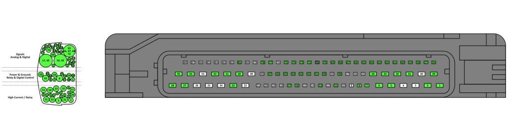
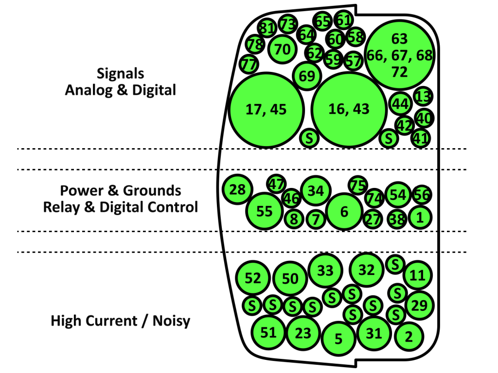
Now that I am 99% sure of the final ECU pinout, I was able to build a map for the ECU connector entry. Things will be getting a little tight in there, so there can't be any unnecessary crossing or layering of wires as they come in. The general idea is to separate wires by "type", and to have them stacked in a closest-to-farthest-terminal way which will be most space-efficient. I am not about to go crimping terminals on and putting them into the housing yet since I want to do that in the actual car, but it is also the case that I wanted to have the wire runs through the large sheath be approximately stacked in the proper order.
I built a little wire layout map based on the connection types and positions. All of the high and mid-current stuff is shielded, with the "S" wires being the shield taps that will be joined outside of the connector housing. Knock, crank and cam sensor wires are also shielded.
If anyone wants the vector art template for a mostly-properly-scaled 88 pin connector (Motronic side) and the mating connector entry opening, it is here:
So, I put together another basic pin board and got things labelled, sorted and arranged with an absolute minimum of twisting and crossing.
I am also going to re-design some of the sensor adapters and stuff. The previous ideas were nice and fancy looking, but too much hassle to actually make. I can get the job done much more simply. The main thing that I want to change is the oil pressure+temperature sensor position. I had been planning to install it in place of the stock oil pressure switch, which would be fine and could be done with a simple adapter, but the thermistor would be well out of the actual oil flow and probably read 10-20 degrees cool. At this point, I think that I will have a little mount boss TIG'ed onto the upper portion where the filter element is. Yeah, it is on the dirty side and if somehow the filter got clogged it would not indicate loss of pressure on the clean side (although the housing has an emergency bypass valve), but I don't plan to forget to change the oil or filter for 100,000 miles lol. An additional benefit of having the sensor up there is that I can use the Bosch Motorsport knock sensors since there will be room for the front one again without the oil sensor down in the way. The stock M42 ones are fine, but I would prefer to not deal with sensors that have integrated wires and which might go out of production at some point.
So I've been looking at the E36X stuff and I'm wondering how your experience has been so far?
They say in the spec sheet you linked that, "a G4X PlugIn ECU is capable of the following features if the supports them."
Incomplete sentence aside, they don't seem to elaborate on this in the E36X document, and have some questionable terms in there (talking about an AFM and how half the pinout descriptions aren't populated - Yes, it's a PNP ECU, but you think the information would be worth putting there for troubleshooting to save even one phone call for support.)
I'm looking at the feature list for the XtremeX and I'm wondering if any of that is disabled (or completely omitted) on the E36X?
Stuff like:
DBW, it mentions an external controller? So does that mean it needs their $300 DBW module? (or could you use the ICV I/O for DBW?)
"Injector Drives 7 and 8 aren't exposed and don't have the hardware required to drive Injectors." Can you still use these for other outputs? (I don't see them on the pinout)
Exactly how much of the XtremeX I/O exists?
I'm not really asking for you to do my research, more so taking the scenic route to the question of: Have you experienced any surprises wrt the above while digging around in it?
These are mostly all things that I have asked Link, actually. They have been very good about answering. Basically, it is an almost fully featured G4X XtremeX, except it is missing the last 2 injector drive FETs, and the high-side driver IC since those are pretty rare to need in an OEM setup. What it does have which the regular one does not are onboard MAP and 6 high-current ignition drive transistors which can fire "dumb" coils directly.
Now, it is the case that quite a few things are not broken-out to the 88 pin DME connector, but they are all accessible in internal expansion connector and the through hole board-to-board connector that couples the G4X mainboard to the Motronic adapter/daughter board. In my case, I do not think that I will need to actually solder to any of those since there are just enough unused aux inputs and outputs by virtue of me not using this in an E36. DBW would require me to tap into some of them for sure (or give up traction control and fuel+oil pressure), but other than that the required hardware is all in there.
Their rationale for NOT breaking-out all of the additional inputs and outputs is that it would make a support nightmare with everyone implementing the E36X differently, when it is supposed to be a PnP system. I actually entirely understand that, and don't really have a beef with it. It would not be too hard to figure out what is what on the B2B header inside using a multimeter and the PCLink software, and Link might even just tell you which pins to use if you asked (I doubt they would give you a full map).
So I've been looking at the E36X stuff and I'm wondering how your experience has been so far?
They say in the spec sheet you linked that, "a G4X PlugIn ECU is capable of the following features if the supports them."
Incomplete sentence aside, they don't seem to elaborate on this in the E36X document, and have some questionable terms in there (talking about an AFM and how half the pinout descriptions aren't populated - Yes, it's a PNP ECU, but you think the information would be worth putting there for troubleshooting to save even one phone call for support.)
I'm looking at the feature list for the XtremeX and I'm wondering if any of that is disabled (or completely omitted) on the E36X?
Stuff like:
DBW, it mentions an external controller? So does that mean it needs their $300 DBW module? (or could you use the ICV I/O for DBW?)
"Injector Drives 7 and 8 aren't exposed and don't have the hardware required to drive Injectors." Can you still use these for other outputs? (I don't see them on the pinout)
Exactly how much of the XtremeX I/O exists?
I'm not really asking for you to do my research, more so taking the scenic route to the question of: Have you experienced any surprises wrt the above while digging around in it?
I have not had time to do much with this project since the last update. Work has been busier than usual and I have a couple of bathroom remodels to do lol. Priorities!
When I find the time, I do plan to take care of the machining work needed on the intake manifold, for the fuel line sensor, and I will probably modify the extra M44 oil filter housing just in case I want to swap it on. I'll get around to it at some point in the (relatively) near future. For now, I have been enjoying driving the car a lot since it still runs quite nicely even with stock management! I do feel like the exhaust is getting sort of loud, making me suspect that the guts of my now decade-old Supersprint cat-back are corroded out. Any suggestions for a replacement? I'd prefer something relatively quiet. The two Supersprint systems I have had have been pretty good in that regard, but they seem to be sort of expensive and only available here and there in group buys.
EDIT: Looks like the SS exhaust is more available now than in previous years. Turner has some coming in about a week from now. Kind of pricey though...
Any idea what the finished would cost? I'm interested in one, maybe two.
Based on covering parts costs + shipping, I can do a small batch of these for $60 each shipped (assembled PCB, 3D printed enclosure, screws & grommets). Two would be $110 since I typically ship USPS flat rate. If somehow these get more popular, the cost would have to go up to make my time worth it, or I'd need to get a solder paste stencil and hack a toaster oven to do reflow lol. Hand soldering these suckers takes more than an hour.
It's been a little while since I have been able to get much done on this project as work has been extra busy lately and home life also has its demands. But, here's a little bit of progress.
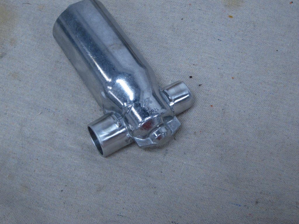
Here is the M50 ICV after I belt sanded the barbs off and then smoothed things out with a convolute wheel. The silicone hoses go on a lot more easily now.
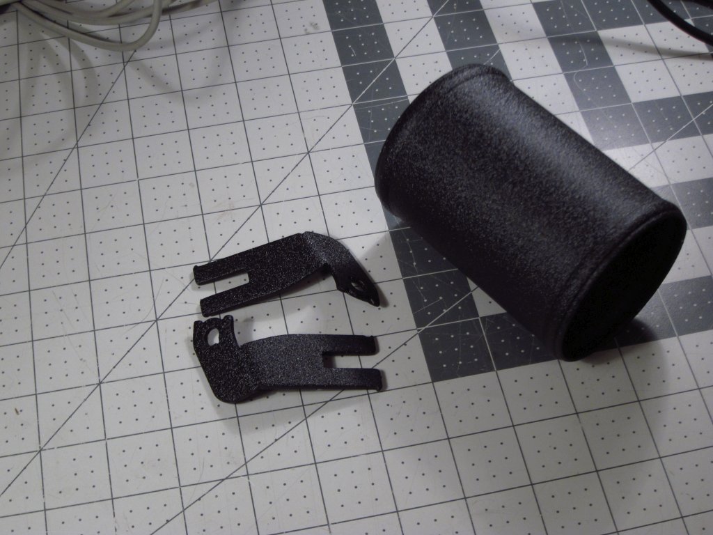
I got the powder coated parts back, and they look really nice in crinkle black. It seems a little coarser and glossier than what I had done on the adapter plate for my M30 air box, but a little dust and dirt should make the tube blend right in, and nobody will ever see the ICV bracket anyway.
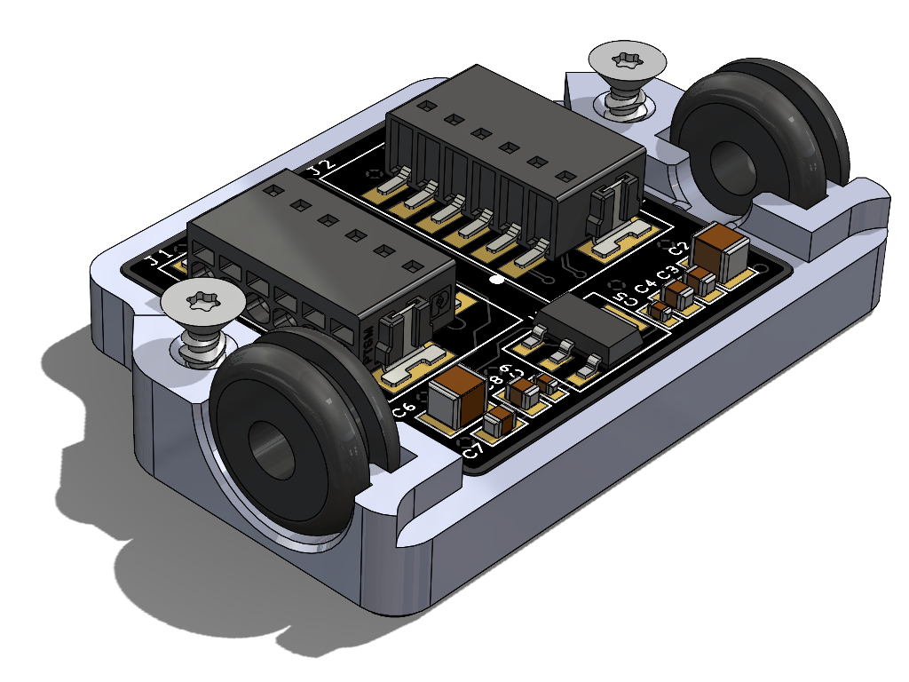
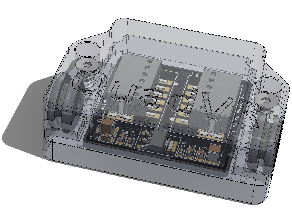
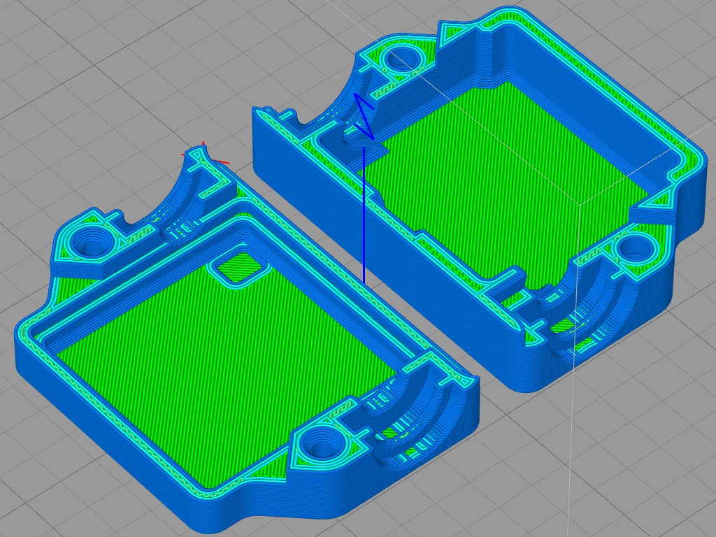
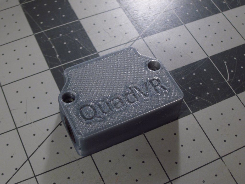
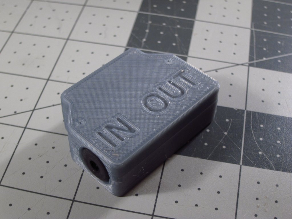
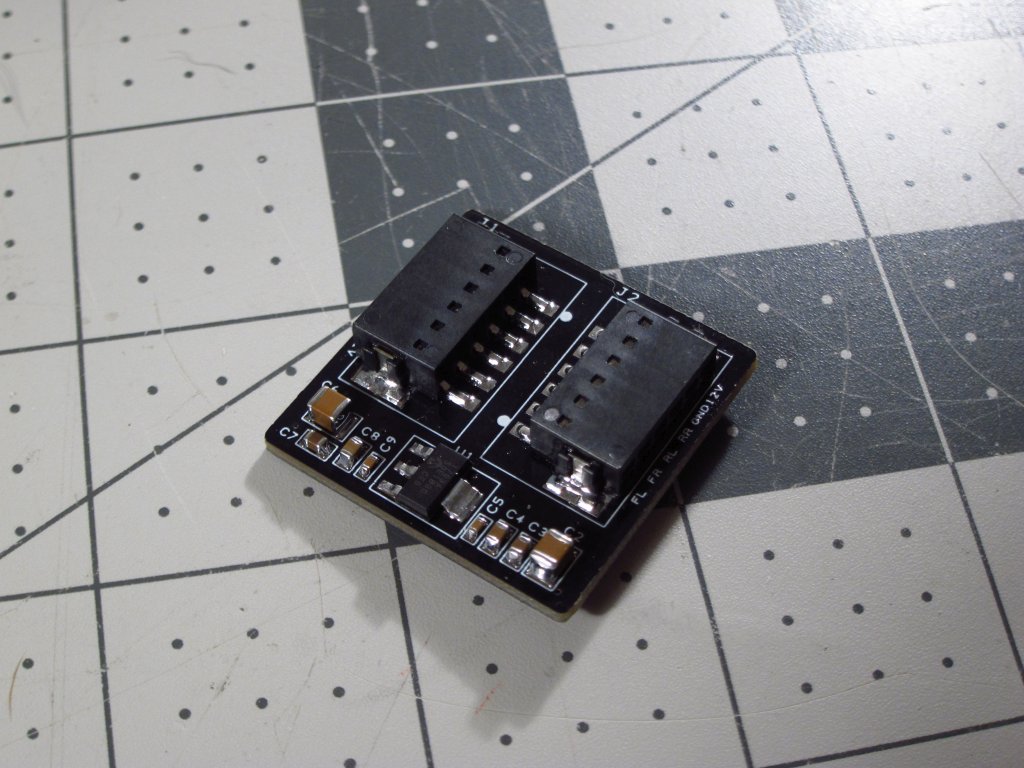
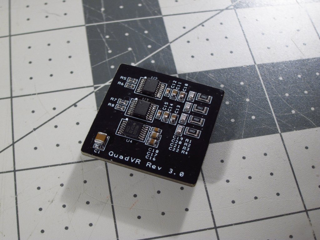
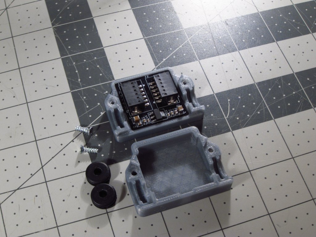
The bigger thing that I finished was the quad wheel speed sensor conditioner. This one was properly laid out and works really nicely on my bench test setup. Noise rejection is good while still being VERY sensitive. I designed a little clamshell enclosure to 3D print for it which would keep it safe and integrate some little rubber grommets.
I kept it fairly simple and easy to 3D print. Initially I thought about integrating some little flexible snaps to hold it together, but tapping screws are a lot easier in the long run, and won't get brittle over time. Also, I would have had to change the print orientation a lot to make strong snaps, which would have meant a bunch of support material being laid down inside the enclosure, and that just makes a mess so I avoid it whenever possible.
It all came out nicely and everything fit well.
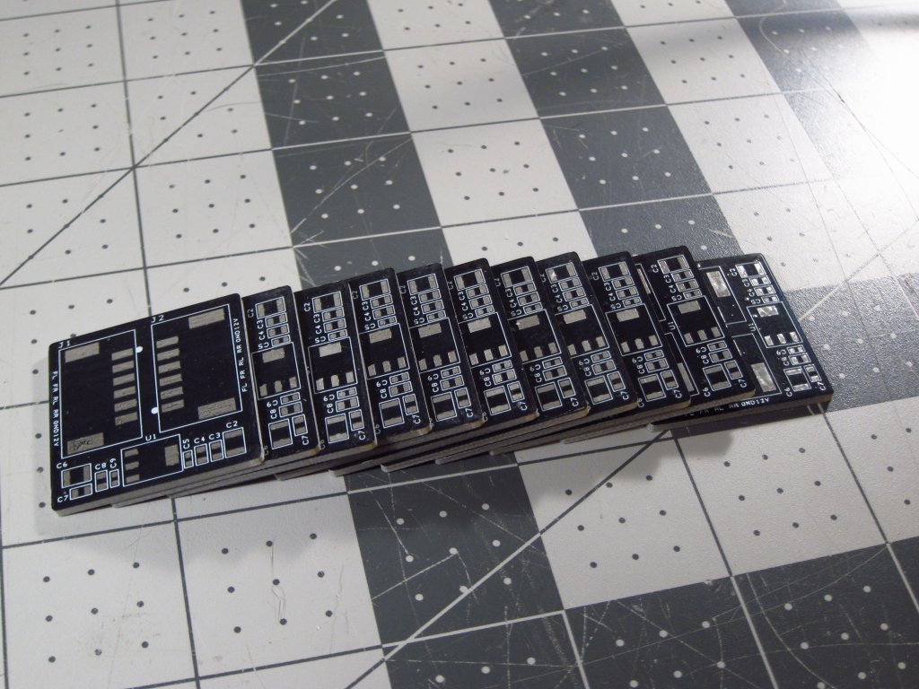
I had a small batch of PCBs made for this. Folks who want one for their ECU projects can PM me and once I have a feel for how many people are interested, I can order more components and assemble them. The automotive qualified parts, particularly the MAX9926's at ~$8 each, are costly enough that I want to know exactly how many I need to order.
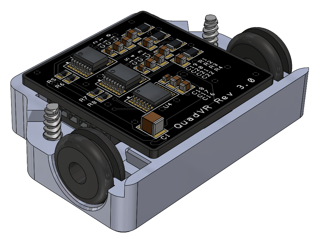
Here it is all assembled, cleaned and sitting in its new home.


Leave a comment: