
I think my plan would be to use a micro controller like an arduino to compare the difference, either front average vs rear average or one front vs one rear and decide when to trigger.
I'm told the ECU just wants a 5V signal from the ASC module on one of pins 80/82. I dug into this a bit in the ETM, and while there's not much info (and an inconvenient typo in the input/output labelling) it "feels" like it wants an input on pin 82, and 80 is feedback to the ASC module.
All the ECU can do is trigger a retard table (and maybe some sort of fuel modifier that is not yet defined?), so I am probably going to have to test this to see what happens.
-
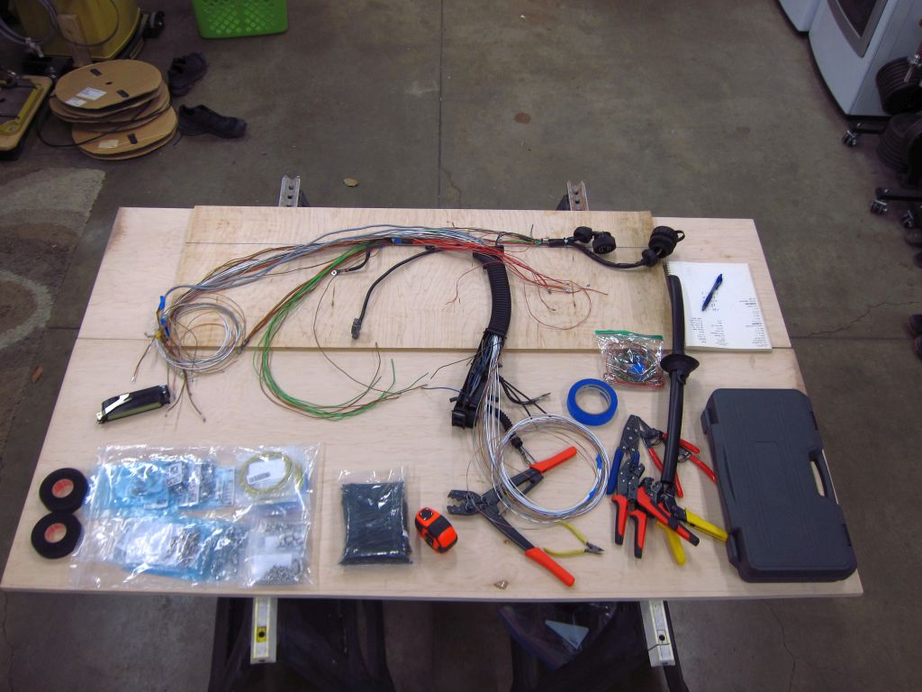
Today's updates...
I finally found a cheap crimp tool that works really well with the 2.5mm (unsealed) terminals. It is not really ideal for the JPT and SPT type terminals where the insulation grips are parallel and supposed to crimp into an "M" shape, but they are fantastic for ones like this with staggered insulation grips. They are low-leverage ones, and the crimps take 2 operations, but that is fine since I do not need to do too many of these.
Crimpers: https://www.bmotorsports.com/shop/pr...roducts_id/364
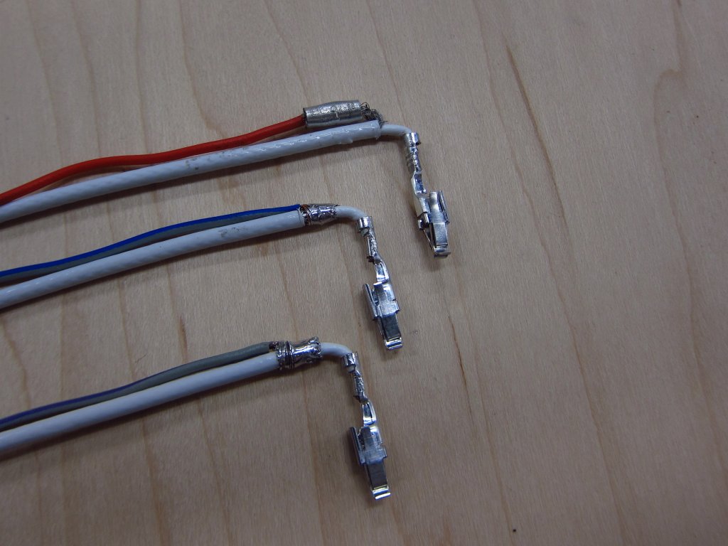
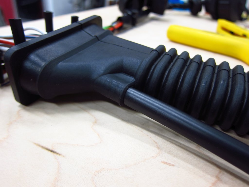
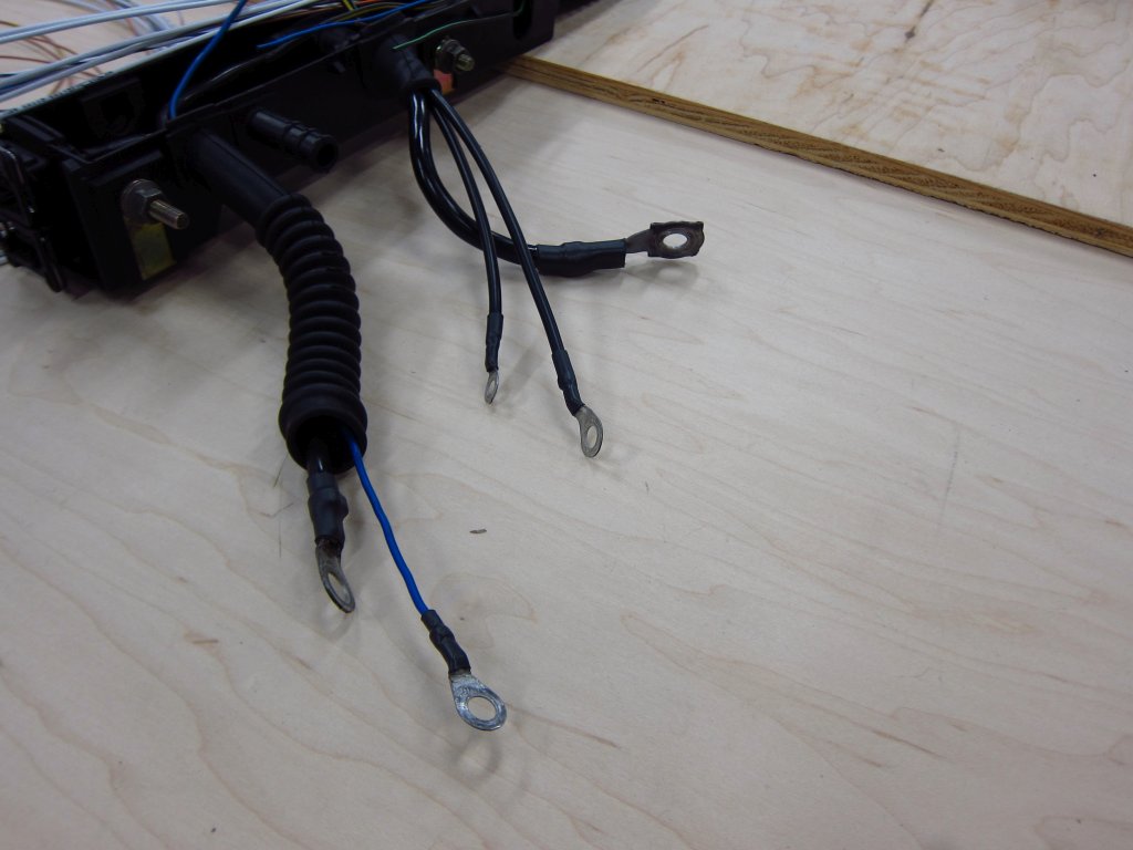
Here is how my new wire runs for C101 wound up (oil pressure light will now be controlled by the ECU, and I ran a new coolant gauge sender wire to eliminate the splice in the wire box). It is not production quality, but it is plenty good for this.
Here is what the crimps look like with the "wrong" tool.
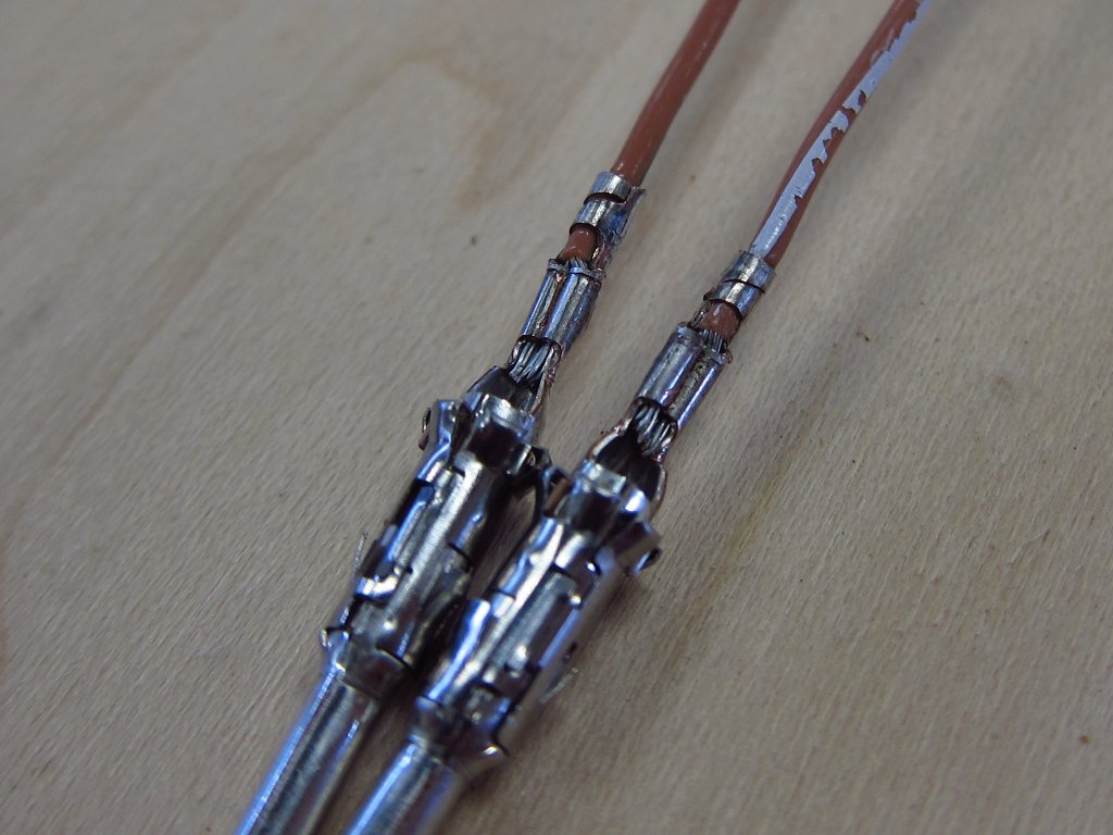
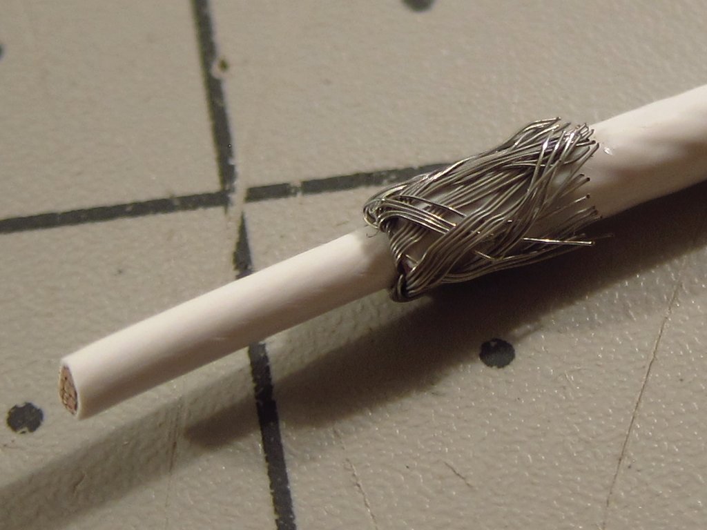
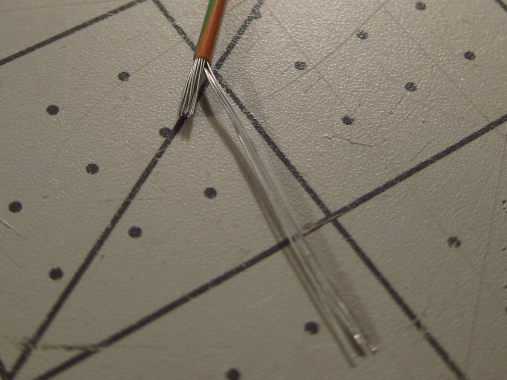
Next, I played around a bit with different methods of shield termination. The factory wiring strips the cable sheath back a number of inches, twists the exposed shielding into a bundle, sticks plastic tubing over it and then crimps all of them together with a grounding wire outside of the DME connector housing. I have never liked that arrangement, since all of the sensitive sensor lines are packed right in there next to the unshielded lengths of ignition lines and stuff. So, I decided to see how compact of a termination I could make really close to the end at the DME terminals. It looks like I can get within a few millimeters.
(top) A parallel crimp is the simplest way to go, but it is just too bulky once you put heat shrink over it.
(middle) Stripping the sheath off and soldering a ground run is very compact, but it leaves jagged soldered edges poking against the central conductor's insulation which could poke through. No good.
(bottom) Stripping the sheath and folding the shield braid back, and THEN soldering the ground termination made the cleanest arrangement. It is only marginally larger than the middle setup, and it is what I plan to go with.
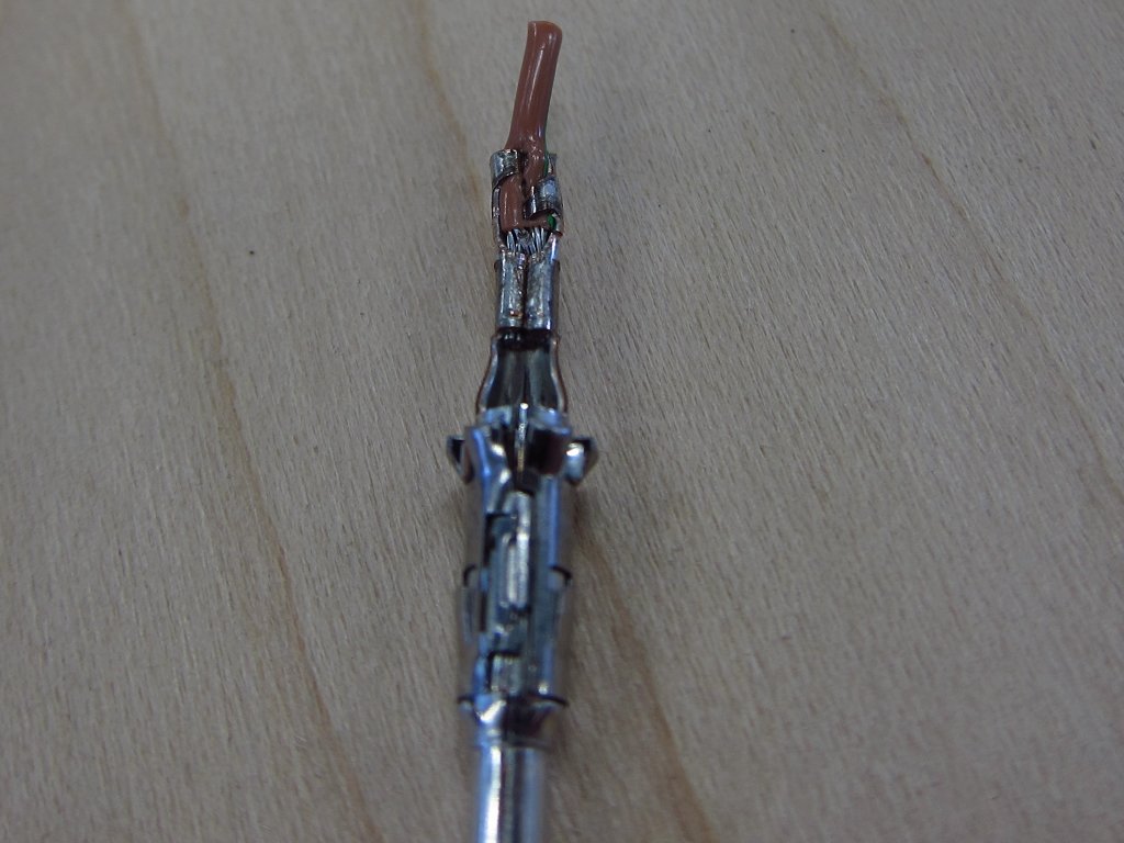
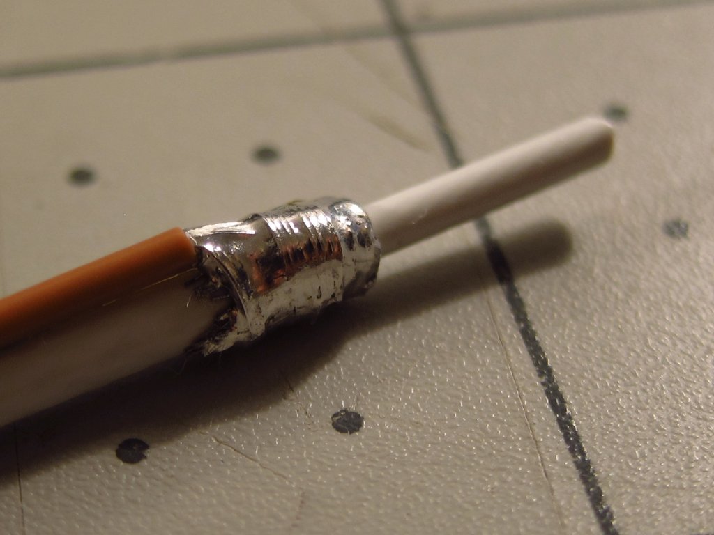
Here's how I will be doing all of the shields. First, strip 10mm of outer sheath off. Then bend the shield braid back over the outer sheath and trim it down to 5mm.
Next, get your ground termination wire and strip enough insulation so that you can wrap the conductor around the folded shield 2-3 times (2 seems like enough). Separate 4-5 strands for the lashing, and trim the other ones down to ~5mm.
Tightly bind the ground wire onto the shielded area. TIGHT! Also make sure that none of the strands (shield or ground) are poking up or out. It should all be nice and smooth.
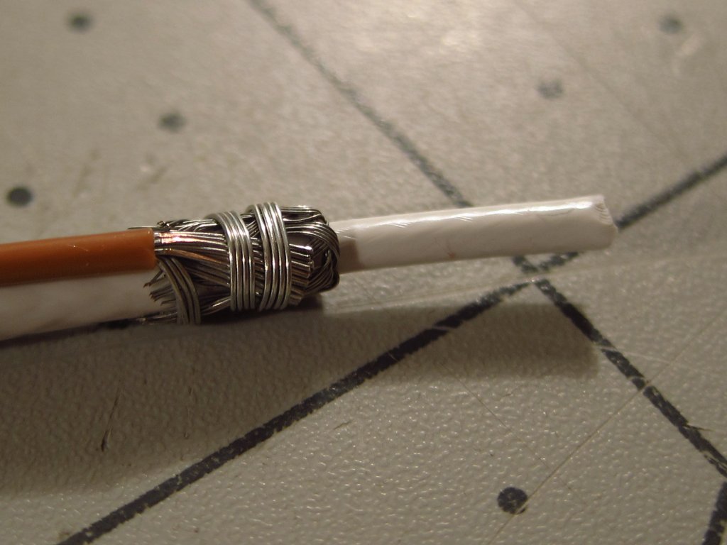
Solder it all together. Don't use too much; you do not want blobs or bulges. Just use enough to wet everything. Normally, I say that solder has NO place in an automotive wire harness, and I generally abide by that. I’d certainly never use solder to splice conductors together or attach a terminal, but shield terminations are a bit different in many ways. Also, sometimes space constraints demand it, and all of these joints will be inside the cabin where temperatures and the elements won't be a factor nearly as much as under the hood. Additionally, I will be cleaning all of these with alcohol to remove as much of the flux as possible (flux will slowly attack the wire and insulation, although it would probably take decades to actually be any kind of an issue).
For those who are interested, here is NASA's guidance for workmanship standards in wire harnesses (or some of it at least). Being that NASA sends ships to space, and I am working on God’s Chariot which will fly majestically in the heavens, it makes sense to draw from their expertise.
I roughed-in a little more of the wiring as well, specifically for the fuel injectors which will be controlled fully sequentially. The wiring for them now runs through the opening where the ICV wires used to come out. It is the most direct route, and it allows me to salvage the 2.5mm2 red/white wire that comes out of the fuel pump relay to power them (it is long enough to reach the injector wire box via this route, but not long enough to go down into the main wire box and then back up).
It was a chore to stuff this 8mm sheath through the opening which was designed for a 4mm sheath. I am hoping that this will not lead to an issue in the future, like splitting open. From the technical info I can find online, it sounds like vulcanized rubber can easily stretch to 5-10x its original length and not creep or suffer other issues. I didn't take pictures of how I got it in there, but it involved folding an end length-wise, stuffing it in about an inch, forcing as many wires into the un-folded side as possible and then pulling that part through with pliers to get it in there at full diameter. Also, Windex makes for a great lubricant...very slippery, not really harmful to anything and it dries fast!
I also replaced the rotten shrink tubing on most of the lugs. For the big ones, I used some 4:1 ATUM shrink...you can use a size large enough to slip over the lug, and it'll still cinch down onto the wire when heated. Most shrink tubing is 2:1 ratio, but if you look around online you can find the higher ratio stuff (I bought a lot of my wire and materials at prowireusa.com).
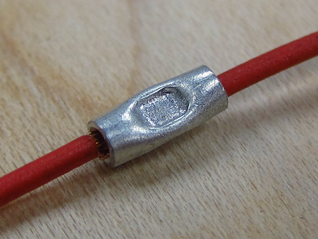
My new favorite type of splice is the parallel splice. They are much more compact than butt splices, and I really like that the working conductors are in direct contact with each other (they overlap inside the sleeve). I needed a longer wire run for the ICV since the fuel injector wires now occupy its old exit point, and the ICV power wire will now go down through the main wire box. Although I swore I would not have any splices in the harness at the beginning, splicing on some more red-white wire from an old scrap harness was just a much more practical solution than chopping off the existing parallel splice holding the bundle of red/white wires together. Although I have plenty of large parallel crimp sleeves, the factory crimps are really nice, and most of the copper wires are pretty heavily oxidized at this point, even many inches under the insulation. It would be a chore to clean up all of the wires to get a quality connection with a new splice, so just doing it for one little wire was the way to go.
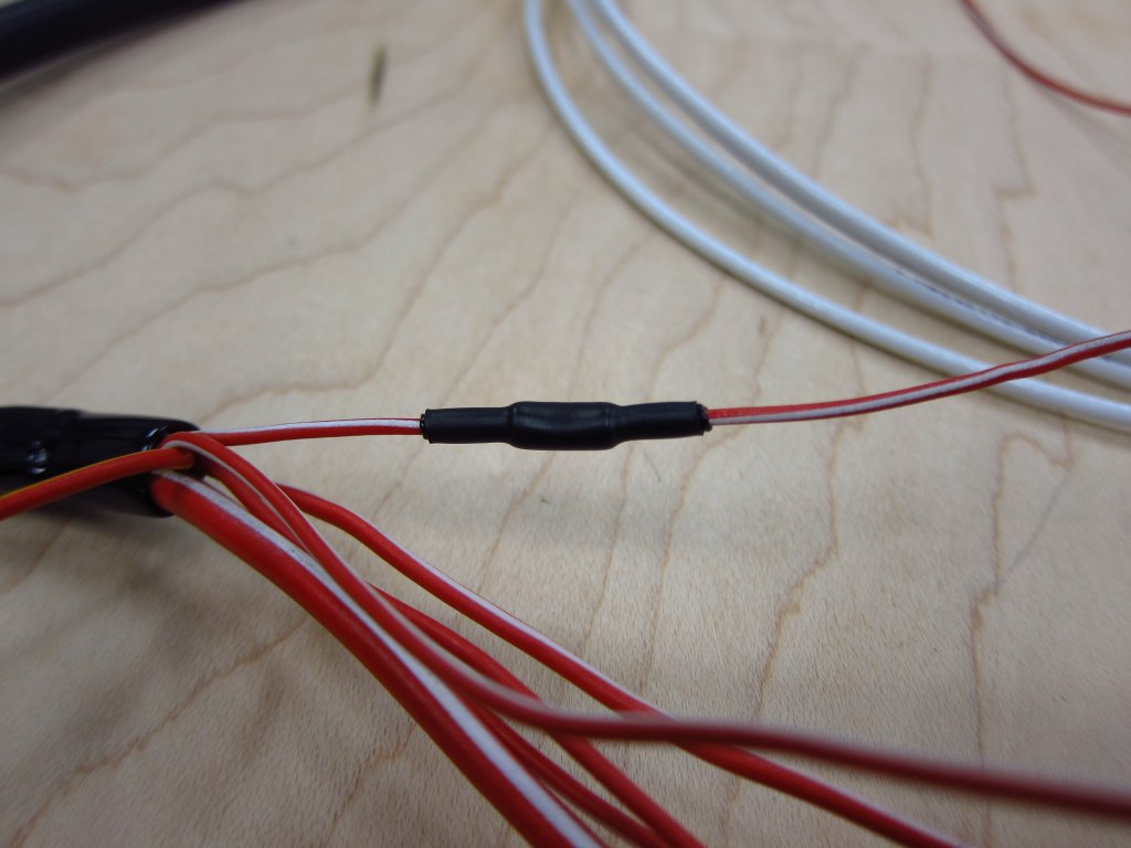
Here's what the splice looks like before covering it up. A very good parallel splice crimper which is also very economical is in the link below. It is the one I am using.
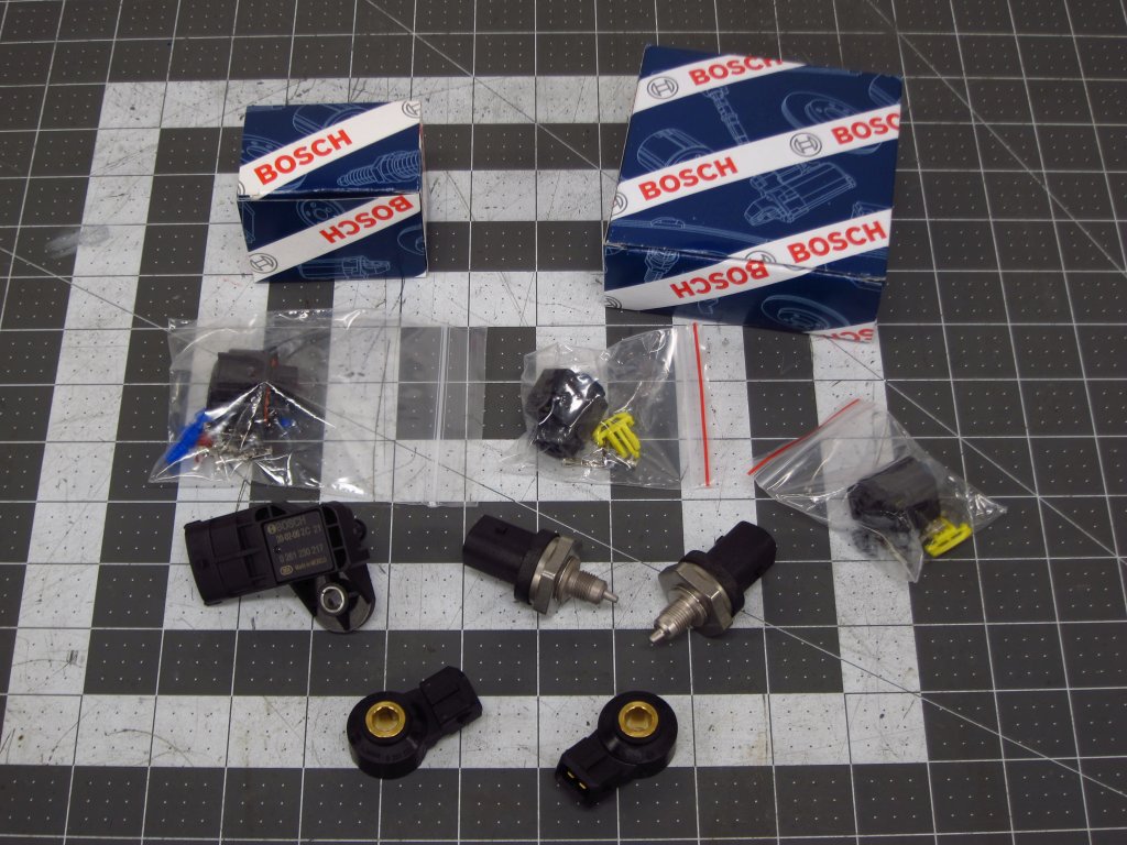
Also, I received a bunch of goodies today! For some reason, knock sensors are a lot bigger than I thought they would be. That reminds me of some British humo(u)r...
Leave a comment:
-
-
Lots of progress since I last checked, this is great!
I might be interested in one of those boards to try to hack together some sort of TC on MS41Leave a comment:
-
More progress...
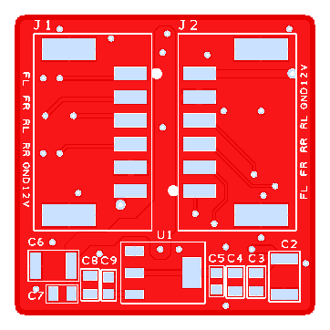
I finished designing a small PCB to condition the 4 wheel speed sensors' signals. It measures 32x32mm, with most of that size being driven by the wire-to-board terminal blocks. I'll 3D print a small enclosure to secure the board & wires, which will be mounted up near the knee bolster inside the dash next to the ABS computer. These little boards are in production now, and I expect to have them in a week or so. The minimum order quantity is 5, so I will have some extras that I can sell (bare board, or assembled) if anyone with a stand-alone ECU wants a quad-VR conditioner board.
Other than that, I have not done too much since the last post since I am waiting on the last of the shielded cable & some connectors to arrive.Leave a comment:
-
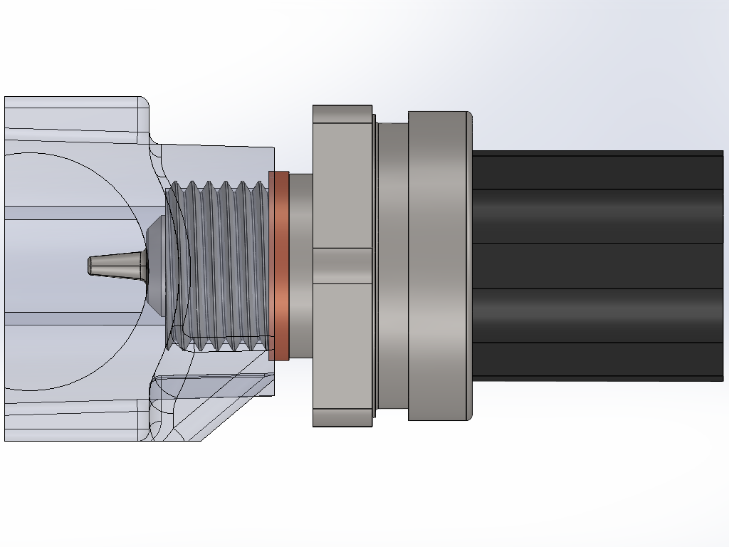
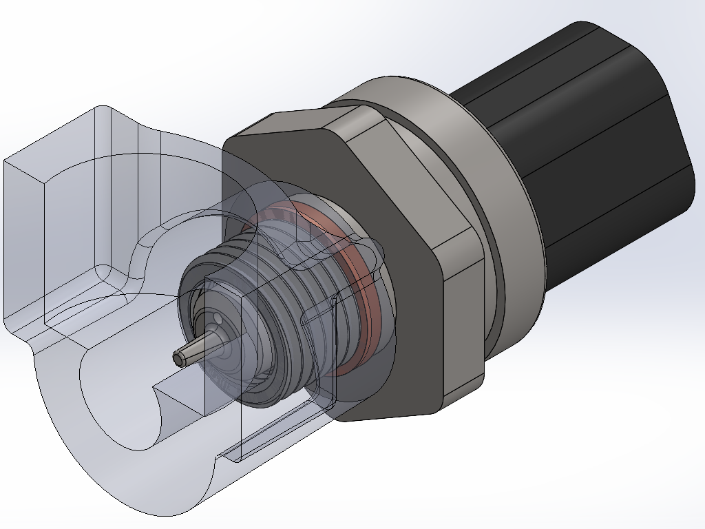
Ha, yep, that is where I am getting my PST-F1's, knock sensors and some other bits from. Naturally, they have been sold out of the M12 to M10 adapter fittings for a couple of months! Thankfully spare M44 oil filter housings are cheap on eBay, so I will see if hacking up my spare works out well.
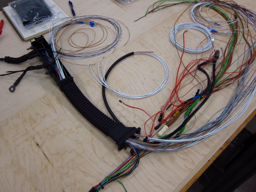
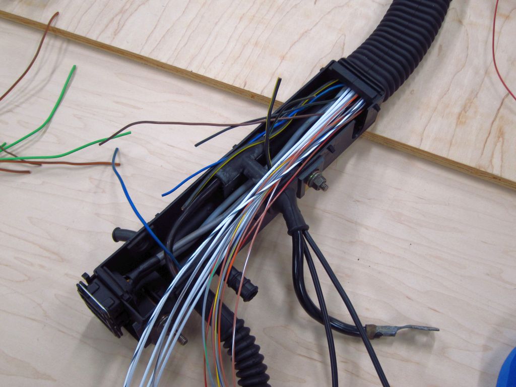
I started doing some basic routing and roughing-in of new wire runs today. There are still a number of items and some of the heavier gauge shielded cable which I am waiting to receive, but I can get a lot of stuff into place while I wait. The plan is to just get the wires in there, but I will not be crimping/splicing/taping anything at all until I can get this fitted into the car. Once I do that, then I can make the final decisions about lengths of things and begin making permanent crimps. I also want to see how things actually end up being positioned, specifically some of the big parallel splice bundles. The big one with all of the switched 12V outputs from the main & fuel pump relays needs to have one of its smaller wires replaced with a longer run, so I either need to cut the existing splice off and make a new one with the longer wire, or just make a butt connection to extend it. The latter is far easier, but the former is cleaner. I only really pause thinking about this because the exposed copper strands from that splice are all greenish, and if the oxidation extends too far up into the wires then I might have to trim off a lot more than I want (or attack them with some fine sandpaper). Overall this is just me having fun over-thinking things, which I am sure you have figured out by now!
Here's what the big wire box looks like with new runs pulled through to it. The existing wires were fine, but they all had those obnoxious splices + rubber caps which ate up almost 50% of the available volume. I understand why they did it that way, to make mass production easier, but I don't want to have to deal with the mess. There are some other splices like that in other places in the harness which I am also removing.
Here's where I left things today. I am going to take it easy and spend the evening relaxing and enjoying the last few hours of 2020. It's been a rough year in a lot of ways, so I can't say I will miss it too much!
Leave a comment:
-
Yeah, my adapter for the PTS is an AN 6 on both ends (one is capped and will obviously feed the turbo) with an M10 port on the side - I should be able to re-drill and tap that hole exactly as you mentioned. I will get the car on the lift this weekend, and I need to drain the oil anyway, so it is a perfect time to give it a shot. That will at least be mechanically more sound, even if for the time being the oil temp reading will likely still be low until I get around to the blower. I am not tracking the car for quite a while yet though, so I am really not concerned about oil temps.
I don't know how many fittings you are planning on designing/manufacturing, but I had good success ordering some bits from https://www.efisolutions.com.au/ in Australia, at least bits specifically designed to adapt the Bosch PTS sensors to AN (and other things).Leave a comment:
-
Wow, I am a bit surprised that they didn't have more dedicated temperature inputs. Thermistors sensors are pretty well known to have noise issues due to their high impedance. But it sounds like you know how to tackle that.
Assuming the hole you have everything mounted into is M12, then drilling & tapping for an AN6 (9/16-18) fitting is a good call. I had considered the same thing myself since the oil pressure switch in the M42 oil filter housing is also M12. Heck, I guess I will be tapping it with 9/16-18 threads since that is what the M10 thread insert has on the outside. Too bad BMW did not specify a switch with an M14 thread...Leave a comment:
-
Aside from the CLT input, it does not have dedicated temperature inputs, just ADC channels. I may just spin up a little board for inline, I am probably going to be pulling the trigger on my first run of cluster boards in a few weeks here anyway and I could definitely fit it on the panel somewhere. The more I think about your comment regarding sensor lifetime the more I want to revisit that though... having the weight of an oil line and restrictor also hanging off that seems less than ideal. Maybe I will try drilling and tapping in directly an AN 6Leave a comment:
-
Ah, yeah I'd be a little hesitant to hack up an expensive item like that. I'd assume that it has a number of "temperature inputs" so could you just re-pin the connector at the ECU to run those in through them instead of regular analog inputs?Leave a comment:
-
These are all good points - and I definitely agree that the sensor position dangling in the breeze there is less than ideal. Unfortunately aside from whipping up a custom adapter/fitting of some sort I don't know if I have any good and easy options to shorten it, but this may well be what I need to do.
I am running an MS3 pro ultimate, which I have not actually found the schematics for, but if it is anything like the MS3 then there is a low pass RC filter on the coolant line. I may well change over the resistor for the other two sensors and see if it helps, but first I plan to adjust my plug wiring significantly.Leave a comment:
-
Interesting stuff.
Regarding the resistor value, changing it around is not likely to make all that much of a difference. IIRC Bosch recommends a 4K6 resistor, and I'd guess that MS has a 1K (same as the Motronic also), but it is not all that important as long as the value is known and programmed in. If anything, going to a higher value would potentially make the noise issue even worse, if it is in fact due to EMI from the ignition. It's super weird that it is so much worse at idle than when running though. Anyway, since the CLT temp signal is nice and clean, and as you mention the input is a dedicated "temperature input" I'd guess that there's just a capacitor connecting the resistor-thermistor node to ground to act as a simple first order low pass filter. Which version of MS are you running? You could probably add the filtering capacitor and/or resistor on the mainboard, since it sounds like you added the resistor near the sensor.
I am 99% sure that the long warm-up time and cooling effect that you see is due to where the sensor is. Heat will conduct very slowly through the stagnant oil, and passing air will for sure cool that "leg" off. But, since you plan to have oil actively flowing through there when you get the blower installed, that will be a perfectly good place for the sensor at that point. The only point of caution I'd make is that the long assembly of fittings plus the sensor & harness being out that far make for a big resonant structure (think tuning fork). I would guess that the life span of that sensor would be shortened. If there is a way to get that tee fitting closer to the block, I'd try to do it.Leave a comment:
-
Agreed, the temperature sensor would be the most likely candidate to to get pushed around. Maybe I should change the resistor I used for the oil and fuel sensors... coolant has a different one (which is actually internal to megasquirt which seemed like too much effort to change, and is not the exact value Bosch recommends, so I had to do a bunch more work setting up the adjusted curve and validating it which obviously ended up being way more work than changing a resistor) and seems to get hit way less. However, the MS may also just be doing more dramatic filtering, as it is known to be a temperature input which won't rapidly fluctuate.
Thankfully I do have data - I can send you actual megasquirt log files if you are equipped to view them and interested, but here are a couple of snapshots:
This was taken during a cruise the other day, trying to sort out an idle issue (which is actually IMO due to issues with an FPR, but a replacement has been sent and I will know soon). I have it divided into RPM/MAP, oil temp (deg C) and pressure (kPa), fuel (temp and press) and coolant temp and pressure.
I quite like the response time of the pressure sensors - this log snapshot does not show it because it isn't zoomed in enough, but the oil pressure follows RPM to within < 75ms, which is the logging resolution I have it set to right now. Coolant pressure also follows very closely, which is to be expected as well with a mechanical water pump, but it is a bit closer to the noise floor and overall pressures are obviously not as high (the log below had a peak of 36kPa/5psi that matched the peak RPM seen of 4k). I have no doubts I could diagnose a failing water pump from the data.
Anyway, there are a couple visible glitches above on fuel and oil temp - and you can see many more below during a warmup from idle, as well as some on the coolant channel. Note that the period I have highlighted, which is essentially how long it takes the oil to warmup to as hot as it will get sitting around idling, is half an hour long - obviously it will warm up faster if you were actually driving, but the oil takes *way* longer to change temperature relative to the coolant (and I have piston squirters, which if anything would speed the process up because they are getting even more oil onto the hot pistons). For reference, in the same log, you can see the coolant warmup to fan turn on (where it flatlines before humping up a bit as I screw with the skinny pedal and idle valve) takes about 360 seconds, i.e. 6 minutes). Anyway, my point is the oil temperature change is somewhat slow.
Now maybe this is due to where my probe sits, in my future oil feed for the blower. One thing though - under continuous highway driving temp seems to drop quite a bit, which is almost certainly due to airflow over the sensor nub sitting there, so a relatively long extrusion like I currently have is not ideal (but I think having the probe a fair bit closer would be more than adequate, really my issue is that the thing is like 2-3 inches long). I mean, I suppose it could be due to the cooler, but I doubt it - the swings I am seeing are ~50c when the car is moving at highway speed and climbing up to 90c after sitting still idling for a little bit.
Leave a comment:
-
Thanks for the info, that is super helpful. So you are saying that you have the oil PST-F1 sitting in stagnant oil at the end of a ~2" fitting where there is no net flow? If so, then maybe I will do a really minimal amount of trimming on the housing, or make an adapter that works with the existing M12 thread and sticks out a bit further to accommodate the M10 thread.
As far as the noise on the temperature line, that makes sense. It is just a resistor divider, meaning a high impedance leg between the ECU and sensor, so it'll for sure pick up ignition noise and stuff. You are saying that you see it irregularly though? That is sort of odd. Got any log captures that show what the signal looks like?Leave a comment:
-
FYI I don't know if there is much of an advantage to mounting the oil pressure sensor such that it actually sits in the oil flow anyway - I have a PTS-f1 on oil, coolant and fuel and my oil one is on a roughly 2" long fitting adapter adventure/future turbo oil tee (this is on an M20).
Pressure response seems to follow RPM exactly, at least with less than 50ms lag, which is the fastest I have bothered logging, and temperature is relatively slow to change, so even the relatively minimal flow at the actual sensor tip looks like it gives me a good reading.
One thing though - all my pts sensors seem to suffer from the same noise glitch on the temperature line. It is pretty infrequent but I have them pretty heavily filtered digitally on the MS and it still gets through, so you may want to consider a hardware filter of some sort as well. Pressure seems completely fine, even with minimal filtering. I do need to re-route my plug wires though, which I think is the source of my noise, so maybe it is just a me problem.Leave a comment:

Leave a comment: