-
Yeah, the alternator and ignition noise in the electrical systems is a real pain on these cars. It's a big reason why I added an active line driver/buffer output stage to the quad VR conditioner board...open drain outputs are great and all, but having a 5ft wire with multiple kOhms of impedance when the MAX9926 output is off is asking for nonsense. So (hopefully) the active line driver will help to sink any EMI that tries to make an appearance between the board and the ECU. A microcontroller and differential bus like CAN would be ideal, but I am hoping it won't be necessary. -
I fooled around a little today to finish up the ICV installation plans. Since the 3D printed brackets seemed to get it where I wanted, I had some little 3/32" mild steel bits laser cut for the final bracket. I will be sending these out for black powdercoating this week as well.
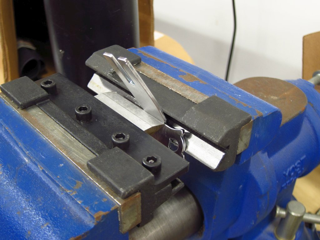
I have a little mini-brake that fits in my vise, and it was the perfect little tool for the job. I once used it to bend a 2" wide piece of 1/8" steel, and that was definitely the upper limit of what this thing is intended for. These little things were no problem at all though. I bent them, took them out to compare to the 3D print by holding it against it, put it back, bent it a little more, checked, etc., until it came out just right. The first one had a little oops in that I started bending it from the wrong side, but I straightened it out and proceeded to bend it the other way. Still, I could tell that the metal was getting a little fatigued, so it's good that I had 2 of them cut.
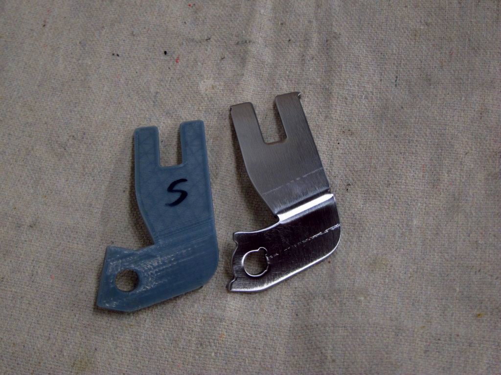
Here is the final part. They were fully deburred and polished on my pedestal buffer using a convolute wheel ("Scotch Brite wheel"), but since they are just mild steel they will be getting some nice matte black powder coating. If anyone wants to use an M50 ICV, shoot me a PM and I'd be happy to sell you the second bracket at a very reasonable price lol.
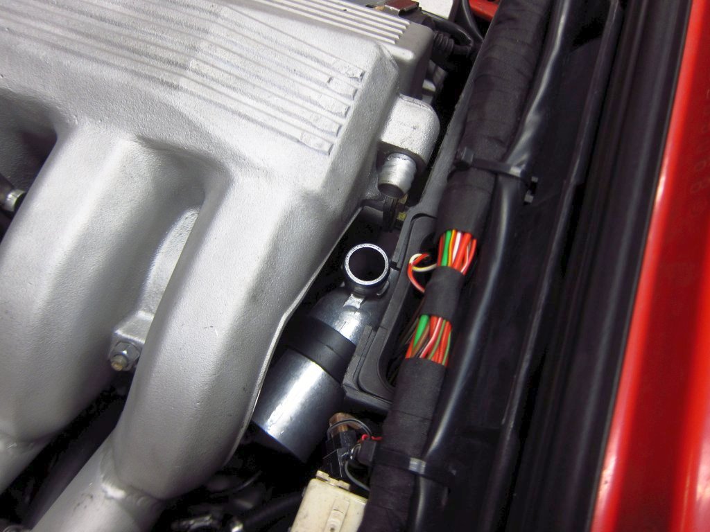
Using it to mount the ICV, everything was exactly where I wanted it.
The next order of business was to get the hoses sorted out. Thankfully, there is an off-the-shelf solution that only required a little extra work. HPS makes some silicone reducing elbows which also have a fairly tight radius. The following parts were used (you can also search the PNs on Amazon and get them from resellers for less + free shipping):
https://hpsperformanceproducts.com/p...ser90062087blk
https://hpsperformanceproducts.com/p...ser90062100blk
I had to go through a few rounds of test fitting and trimming, but it worked out well.
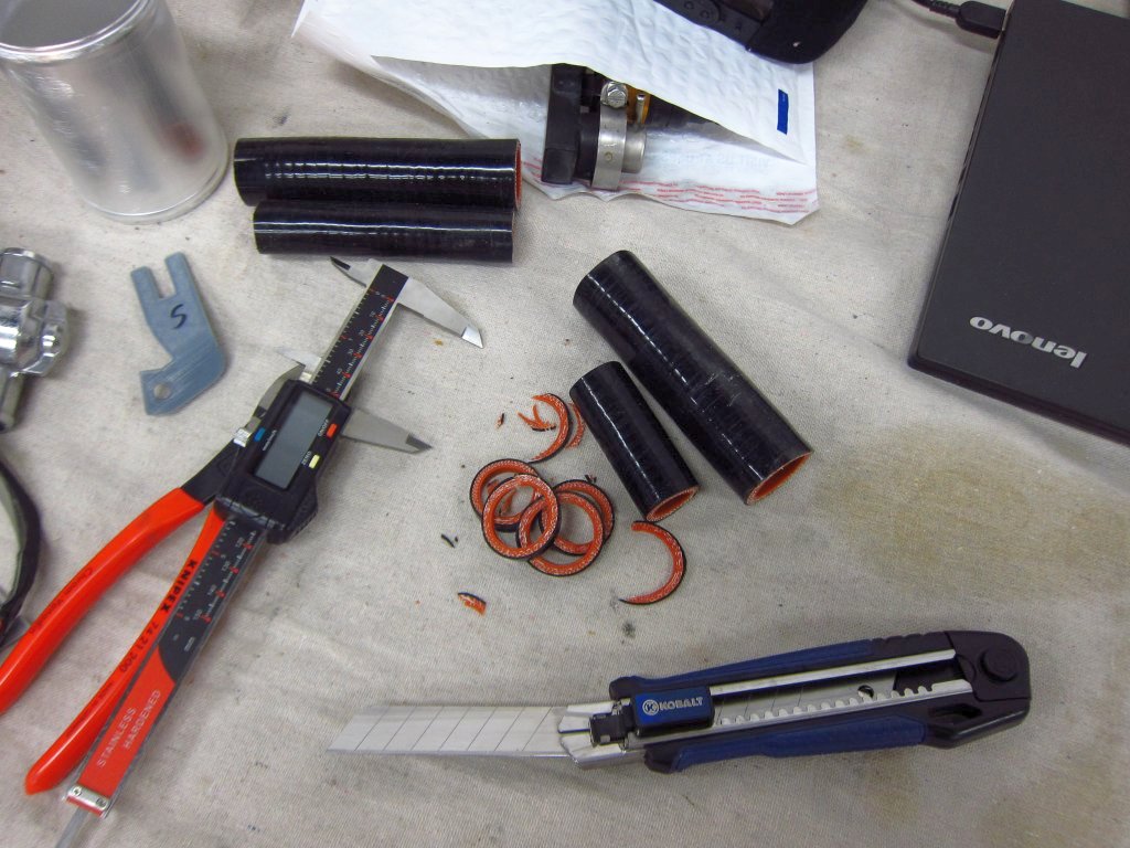
Here is how they fit after I finished with the trimming:
The only "questionable" part of this was the fact that I ended up shaving the barbs off of the dummy ICV. I was able to get the elbows on over the barbs but it was a giant pain and the fit was not amazing after trimming them and having the barbs up in the start of the 90 degree turn. If the hoses were for high pressure fuel I would not remove the barbs, but this is just the ICV which is never actually under positive pressure, so hose clamps will be just fine I think. I will do a much better job of shaving down the actual functional ICV that I will be using.
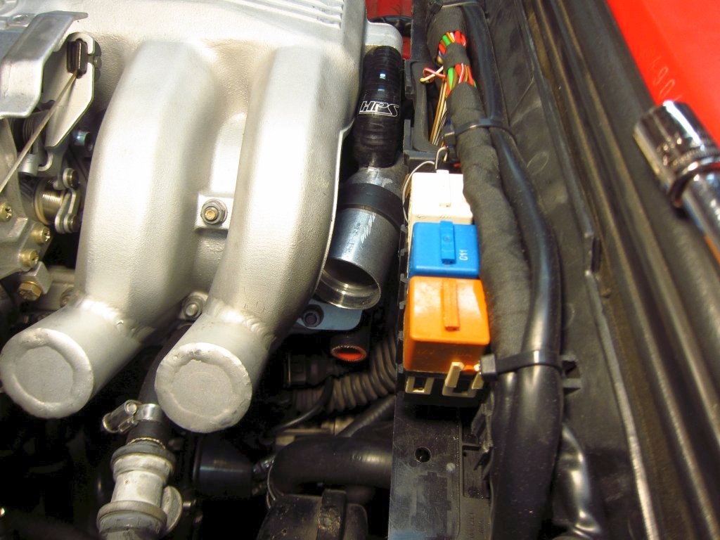
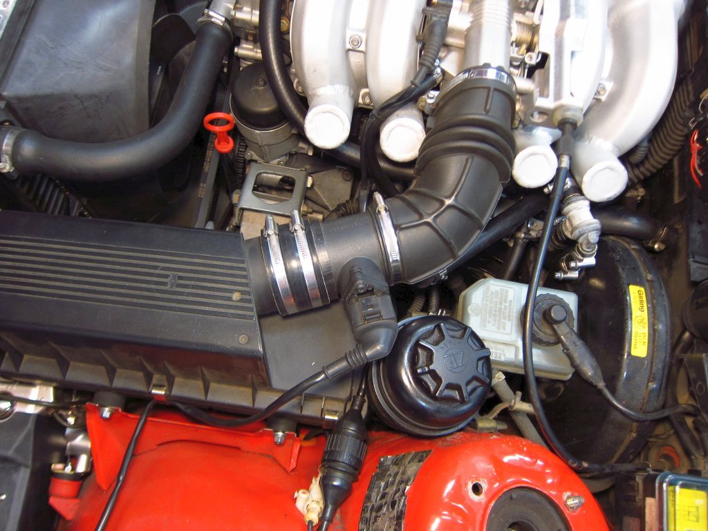
The other thing I took care of was making sure that my MAF removal plans were going to work. As you can see from my setup, all I really need is a straight tube section.
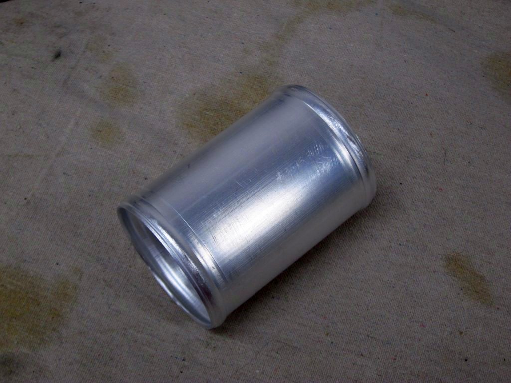
And wouldn't you know it, HPS sells the perfect part. No need for any fabrication at all, other than a little de-burring of the sharp edges on the ends. This is the part:
https://hpsperformanceproducts.com/p...ll-4-inch-long
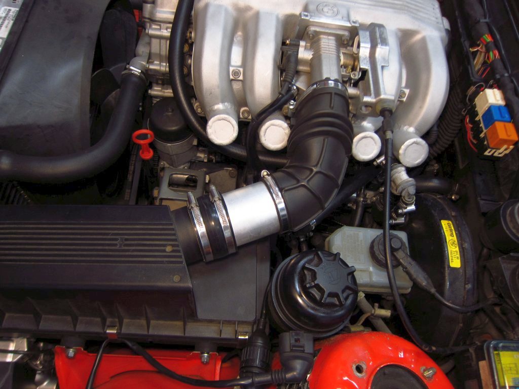
Here it is installed. It will also be powder coated in matte black with the ICV brackets.
That's it for now. The remaining mechanical items for me to do are to machine the fuel line tee for the PST-F1 sensor and to machine the intake manifold for the PST-1 MAP+IAT sensor. From there it is all wiring harness construction.Leave a comment:
-
Pretty much the only time I have had to touch asm on the TI Hercules MCUs is fault handlers and scheduler related bits, thankfully. I generally work almost entirely in modern C++, there are definitely standard library bits that need to be avoided in the embedded context but generally speaking I find it so much better to work with than C. The metaprogramming, atomic support and compile time capabilities blow macros out of the water and let you really leverage the compiler to build fast and/or space efficient code. Agreed about the computing power as well - it is extremely cheap to implement fast :multiorder IIRs and whatnot, ARM even has some easy to integrate libraries that make use of core-optimized assembly for example, which is going to make my life much easier on the cluster work since these old cars aren't exactly electrically quiet.Leave a comment:
-
Ha, whoops! I have not worked with those MCUs, but it sounds like there's a bit of a learning curve, probably especially if you are working in ASM or C. After many years of writing PIC and dsPIC firmware in ASM, I have to say that I am a fan of the "dumbed down" C++ Arduino environment and the Teensy platform. A lot of stuff is far from maximally optimized, but there is so much computing power that it is largely irrelevant in a lot of cases.Leave a comment:
-
The challenge with those MCUs is all the safety stuff - ECC and parity everywhere, tons of monitors, redundant CPU cores, etc. There is a bunch of associated complexity in terms of handler routines and fault modes, as well as various reset types depending on fault source etc.
Anyway long story short I loaded a binary while hacking together super basic LED hello world code that immediately trips some of the aforementioned goodies, basically forcing a reset loop. Seems to be too tight for the JTAG emulator to stop it. It may be possible to recover it... but I bought two, so for now I have added it to 'the pile'.Leave a comment:
-
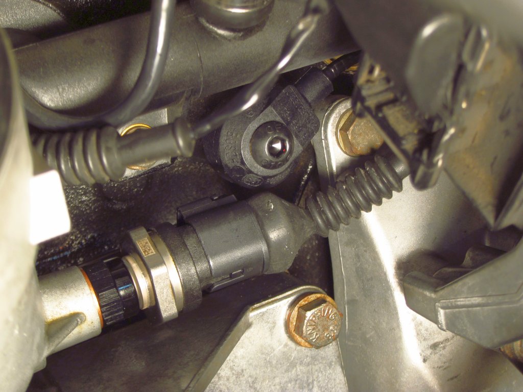
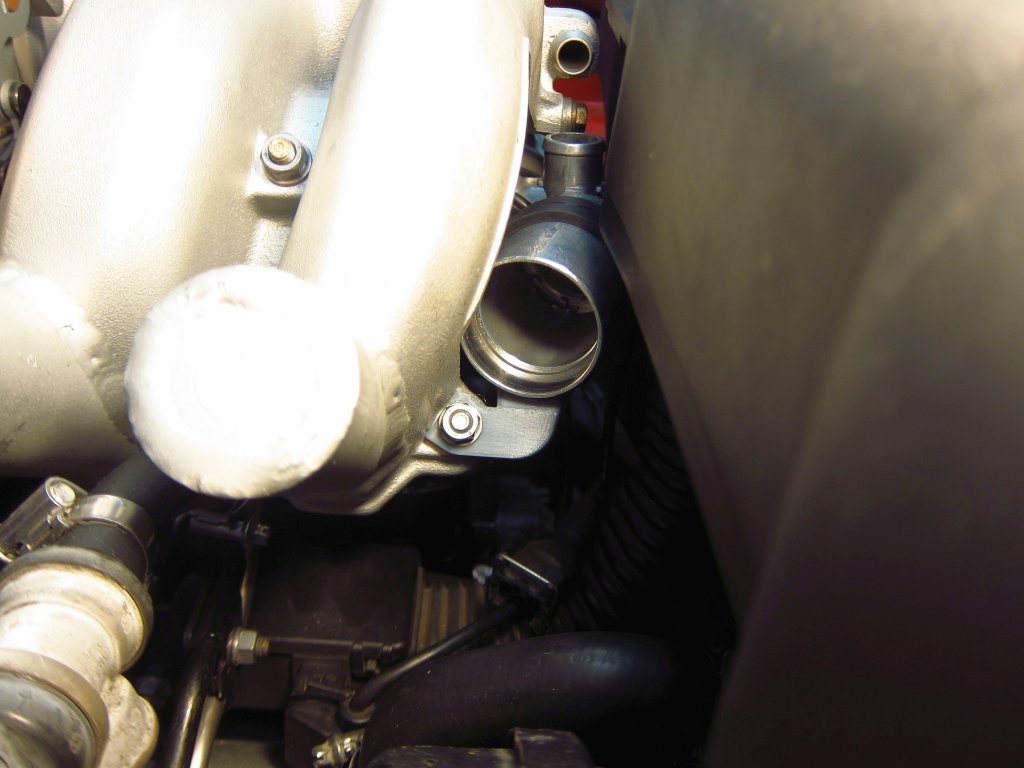
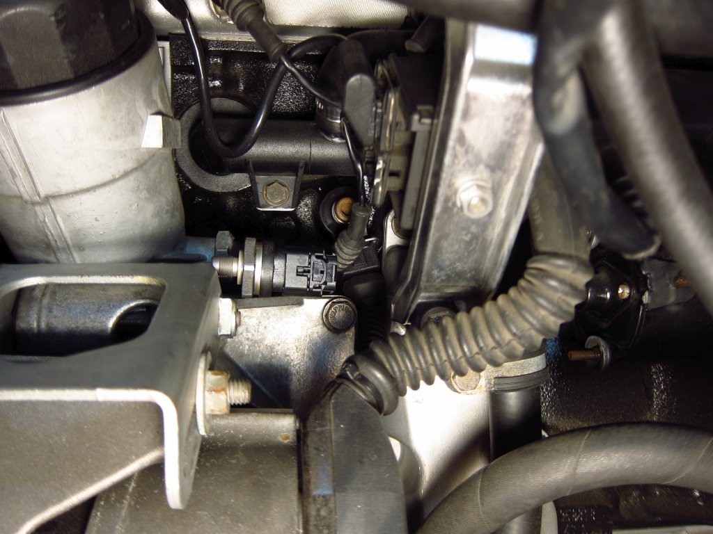
Today I sucked it up and made a little bit of an oily mess to test fit the PST-F1 and make sure that it would clear the knock sensor. At first I tried to eyeball the fit, and came up thinking "oh sh*t" when it looked questionable lol. So, I removed the oil pressure switch, tried to control the oil drainage (I'd guesstimate that ~6oz came out before the "clean" side of the housing emptied out) and installed the sensor. It was close, but it clears the knock sensor with the connector and boot.
I don't entirely like how far out of the oil flow the thermistor tip is when using the thread adapter. It is probably 35-40mm away from where oil flows, and that's a lot of stagnant oil. Now, the housing is aluminum and conducts heat well, and has the full volume of oil flowing through it constantly, so I think that it should heat up to full temperature pretty well, but the response will probably be a little slow and I worry that it will cool off at highway speeds. I have a spare housing that I was thinking of machining to allow the sensor to be 10-15mm closer in than it is with the adapter, but I also don't really want to have to pull my nice clean, new engine apart again lol. The oil filter housing is pretty easy to swap, but for now I will see how things go with the adapter. Worst case, the response is slow or gets cooled by passing air and I swap on the machined housing.
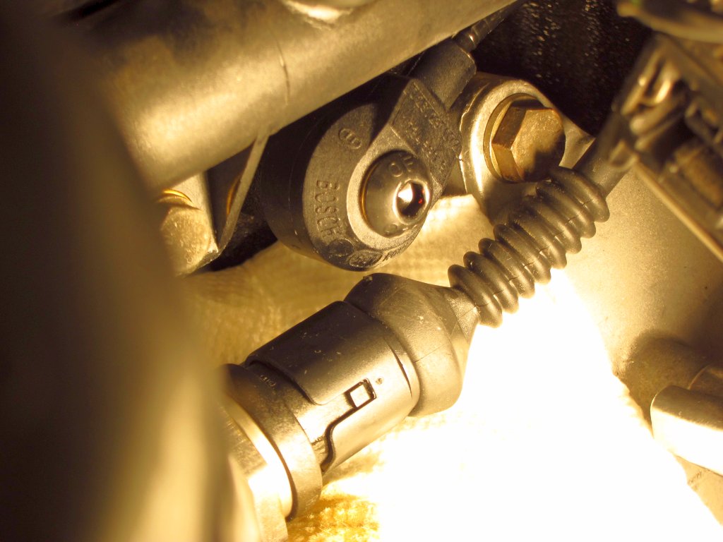
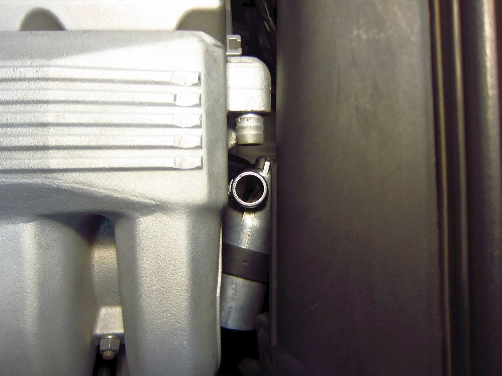
Here it is with a bit more light. The connector is sort of trapezoid shaped and in this orientation it has about the maximum amount of clearance. here it is with more light.
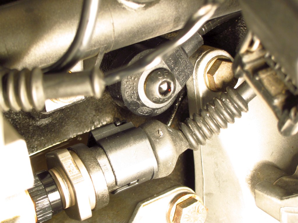
I then unscrewed it a quarter turn to get the wide side of the connector & boot aligned with the knock sensor, and I still had ~1mm of clearance. So, even if when this thing gets installed for real it aligns in this "worst case" orientation I will have clearance (more than this actually, since it will be at least 1mm further toward the housing when fully tightened and compressing the crush washer properly). The knock sensor definitely needs to be pointing toward the rear though, as it would interfere if the wire was coming out toward the front. Anyway, I breathed a small sigh of relief once I saw that things would fit well. I could have always bought myself 2-3mm more by eliminating the boot since the connector uses individual wire seals which provide some protection & strain relief, but I am happy that the boot will fit (it is an "extra" from a 3-position JPT plug from a hacked-up harness).
That's it for now. I have other non-car stuff I want to focus on for the rest of the long weekend lol. On the one hand I enjoy projects like this, but on the other hand I can get carried away with them and put way too much mental energy into them. I can feel that I need to take a step back and occupy myself with some other stuff for a week or two!Leave a comment:
-
Ouch. Did you have some of the code protection / encryption stuff enabled? I have always been paranoid about that with the Microchip devices I've worked with in assembly since it sounds like you will very quickly end up with an unusable device if you make a mistake. Thankfully, most of them are like $5, rather than $50!
Good work on the cluster project BTW. I have been following along with it and it is pretty cool. The stock speedo and tach are certainly nowhere near accurate or linear, and I've always thought it would be cool to have one powered by proper modern electronics, while still looking stock(ish).Leave a comment:
-
Ha, been there. Spent hours and hours a few weeks ago just to figure out I was pulling down a line I should have pulled up on my proto cluster board... only to load a buggy binary and lock myself out of a $50 MCU (all the safety reset goodies on the ti chips can be a bugger early on, and I should know better...)
Keep at it man, looks like great progress.
Leave a comment:
-
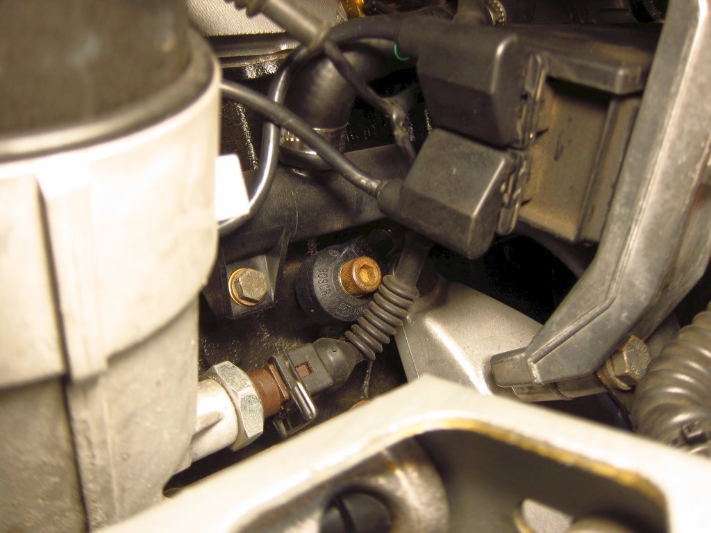
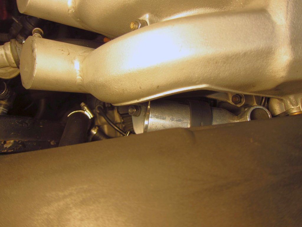
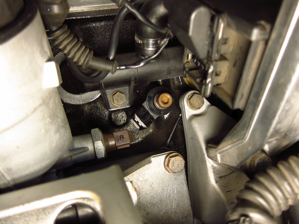
I got the stock M42 knock sensors today and did a quick fit check. These are definitely going to fit better, and I can keep the oil sensor in the filter housing.
Here is how a stock one fits with the wire exiting toward the rear, which is how I think I want it to go so that I can install the receptacle in the bottom of the wire box and have the sensors plug right in. Even with the other stuff in place, it is not interfering.
Here's how it looks with everything out of the way.
I could also turn it around and have the wire come out the front, so I have that as an option if necessary.
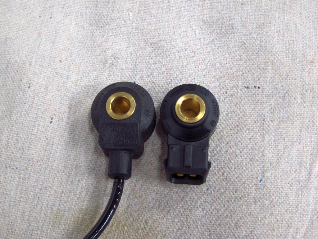
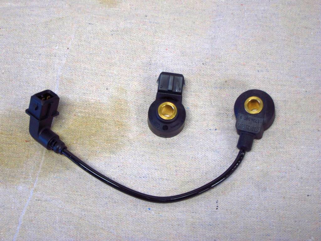
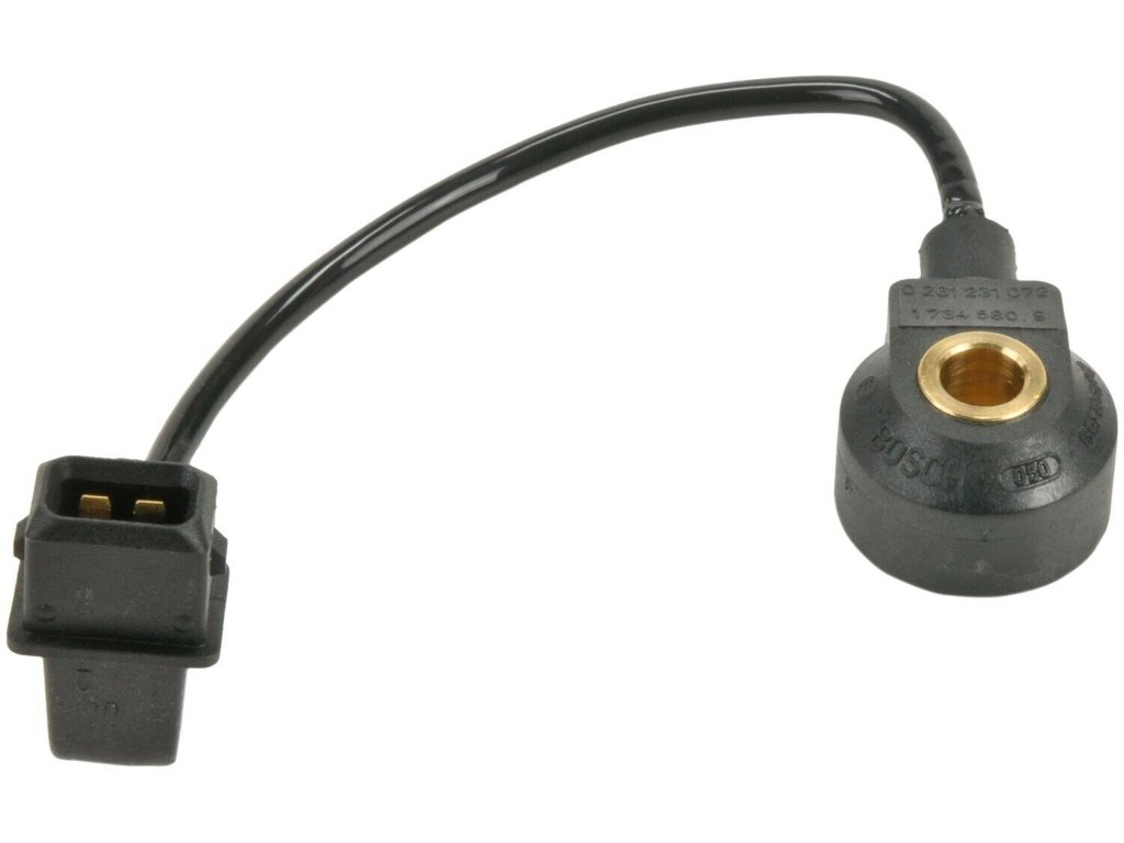
Here is a comparison between the M42 stock sensors and the KS4P sensors I had initially wanted to use. The stock ones are actually slightly larger, but having the integrated wire makes it a lot shorter overall.
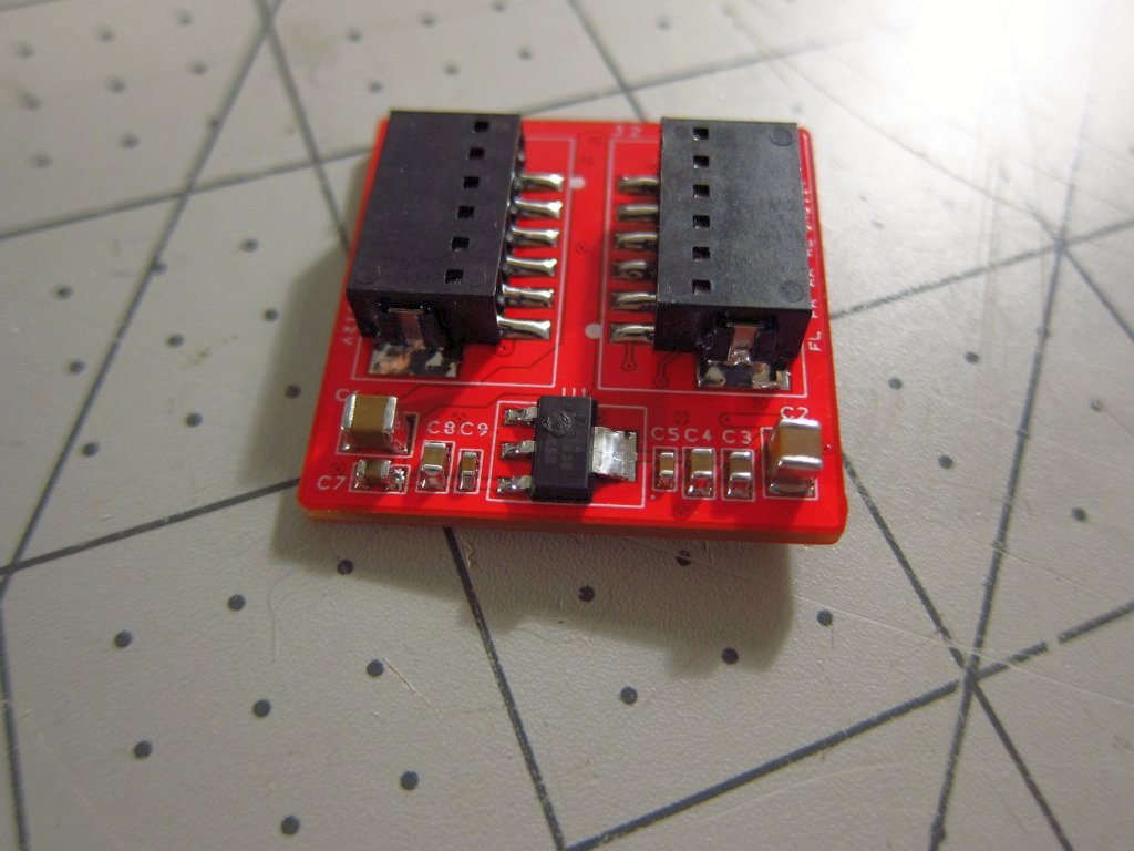
Also, I put together one of my little wheel speed sensor boards. Unfortunately, I mixed up the footprint for the 5V regulator and fried it instantly lol (you can see the little burn spot where the magic smoke escaped). I corrected the issue and ordered a new set of boards. After removing the regulator and just powering the thing directly with a 5V supply, I was able to verify that one of the conditioner chips was working correctly, but the other one got cooked. Oh well, live and learn, and double check the datasheet!
Leave a comment:
-
I got a little more done today, this time focusing on the ICV and how to mount it. Thankfully it does look like I can position it behind the intake manifold like the original one, although it is a tight fit!
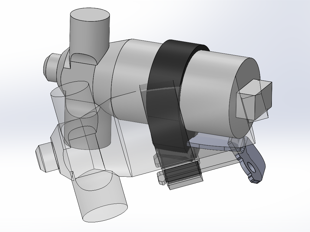
Here is how it will sit (solid) relative to where the stock bracket holds the ICV (transparent).
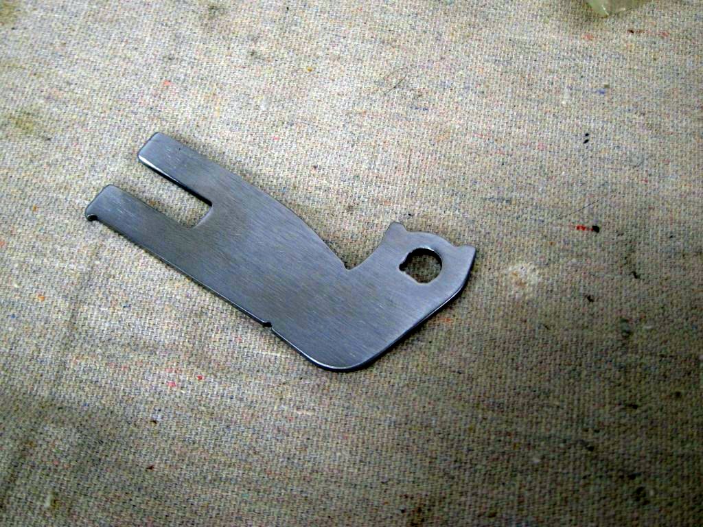
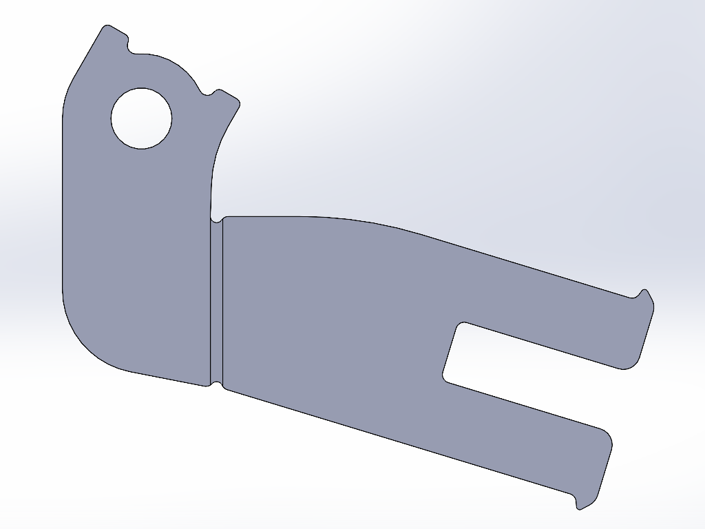
This is how the new one will look compared to stock.
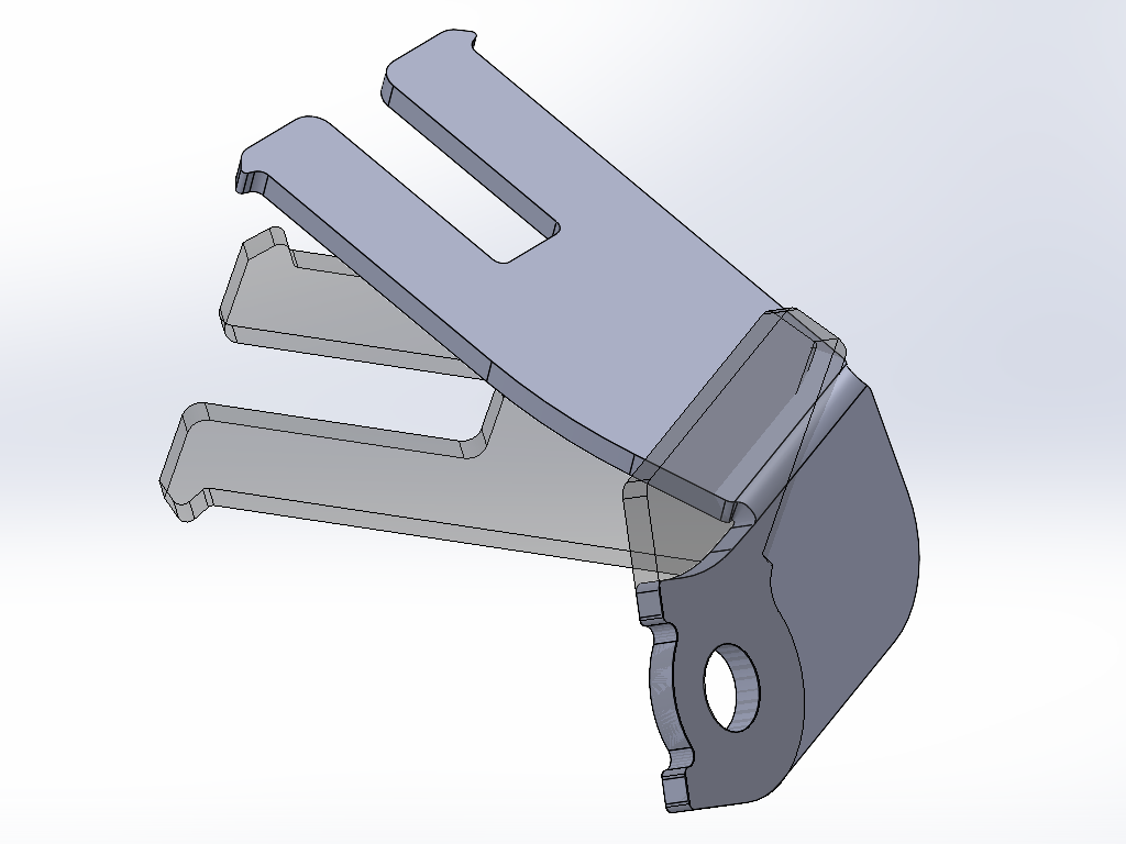
It is a part that can pretty easily be laser cut from some 3/32" (2.4mm) mild steel sheet and then bent in a vise.
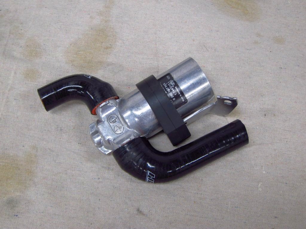
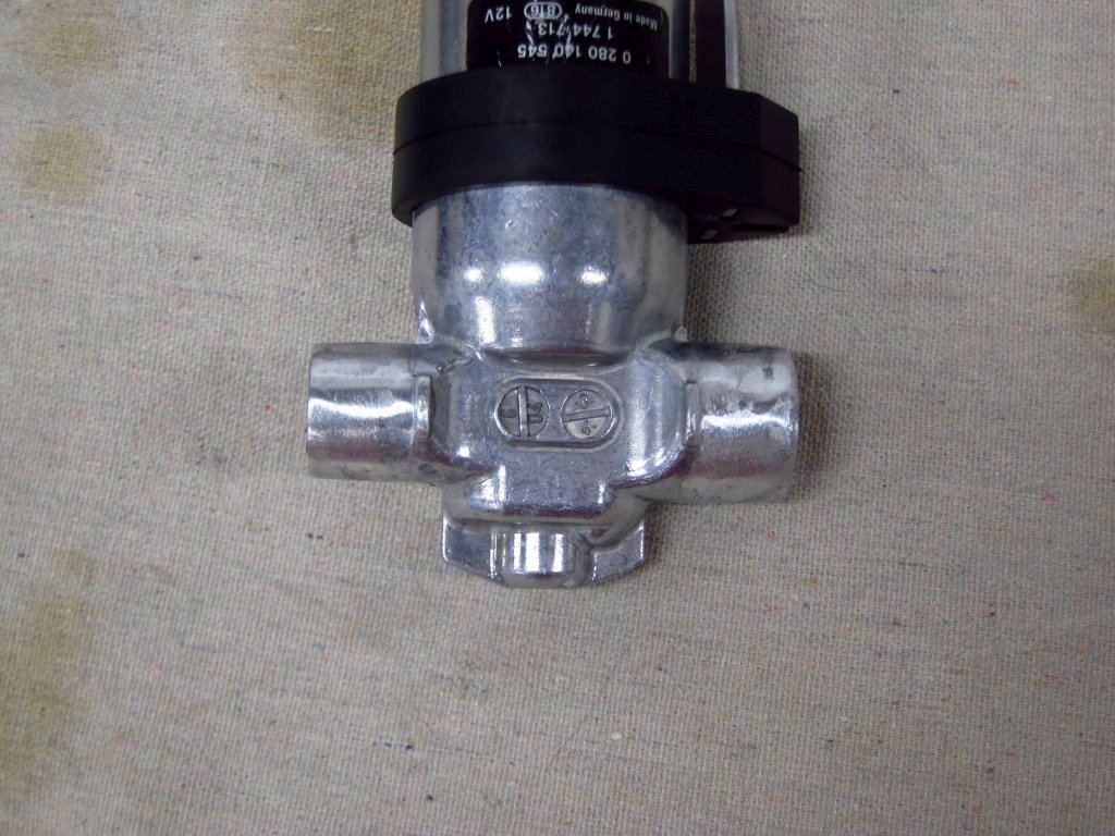
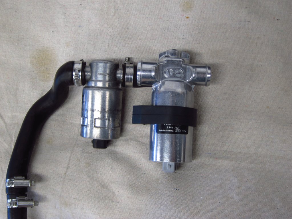
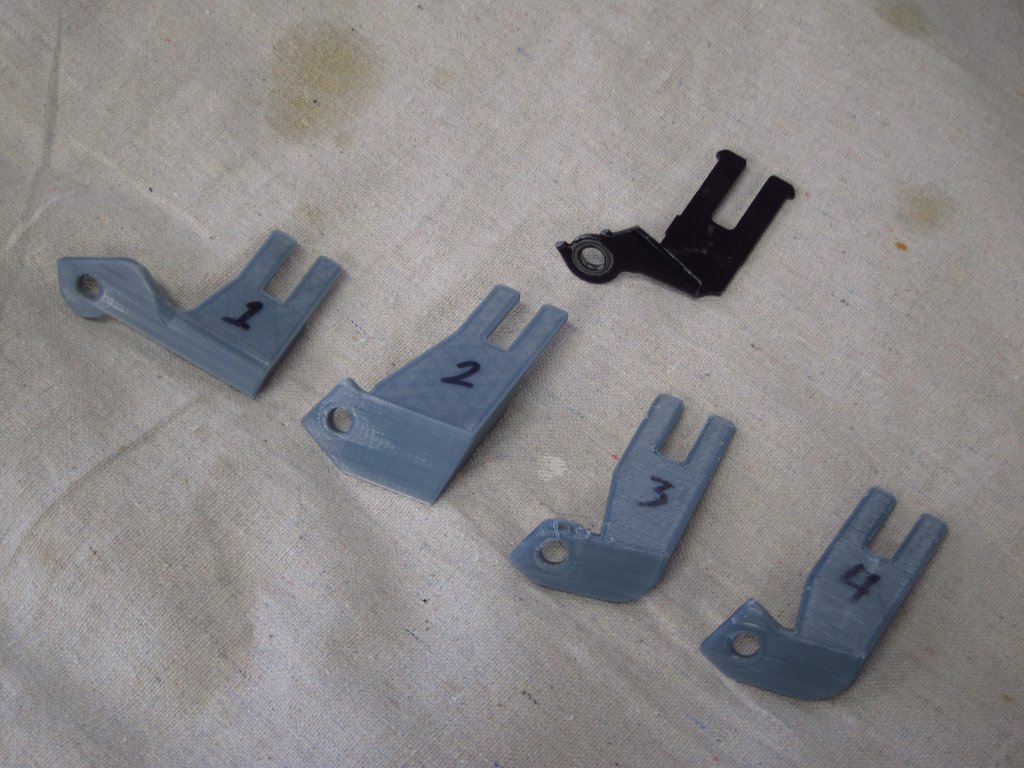
As far as being sure that it works, I 3D printed a number of test parts to hold the M50 ICV. Looking at the M42 and M50 ICVs side by side, you can see how much longer the M50 one is.
It took a few tries to get things exactly where I wanted them.
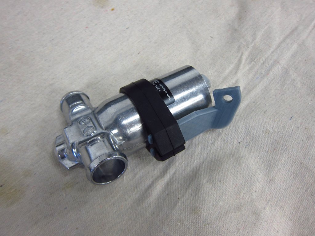
Here's the final 3D printed test bracket assembled onto the ICV and grommet.
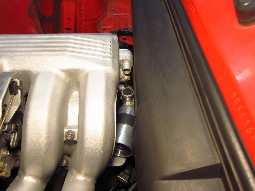
You can see that it is a TIGHT fit back there, but there is enough clearance everywhere. This thing sort of nests into the manifold runners a little, but there are 3-5mm of space all around. I have no idea how awful it will be to get the lower hose on there, but I guess I will find out. Selecting hoses and adapters is the next thing I need to look into, but now that it is in place I can narrow things down a little.
Leave a comment:
-
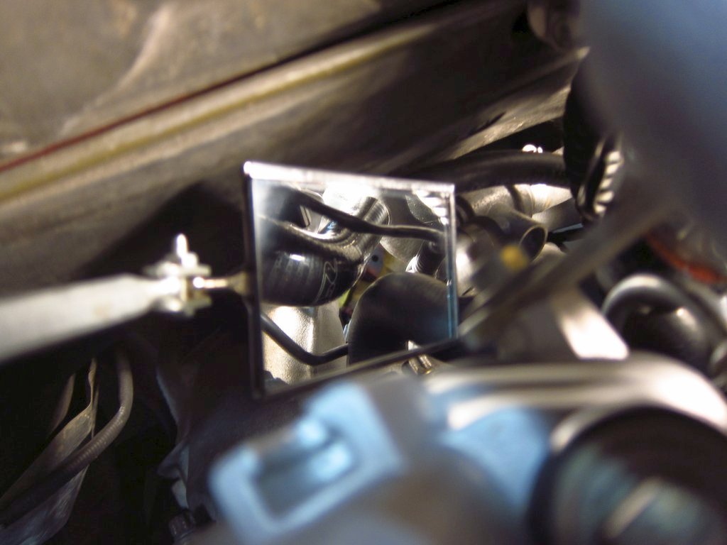
I had a chance to play around today and start figuring out where things would go and how they would fit. First, I used a 3D print of the MAP sensor and connector (Bosch provides 3D models thankfully) to see if I could clear the hood insulation with it mounted on top of the intake plenum. My preferred location would have been the flat-ish area right beyond the throttle body, but there just is not enough clearance there and I don't want to chop out the insulation (although that would probably be the simplest solution. The next best place seemed to be on top, more or less aligned with the runner for cylinder 3.
To check clearance, I taped my cheap USB "endoscope" camera in various places and looked at how things fit with the hood closed. You can get these cameras on Amazon for like $20. They are sort of useless for checking inside cylinders and stuff since you can't control the articulation, but they come in handy in a lot of other places.
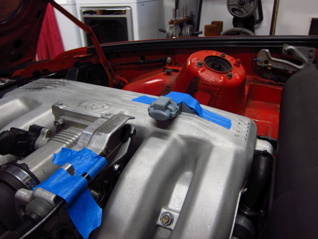
Here's the clearance with the sensor sitting on top of the cosmetic rib things on the plenum. I am going to machine a depression there to give this thing a nice flat surface to sit on, and to install a little sleeve thing to allow the o-ring on the sensor to seal (I removed the thermistor & inlet portion of the sensor that stick out the bottom before printing).
To gauge how much clearance I actually had, I adjusted a piece of tape until it just touched the insulation. With the MAT sensor there, I have 3mm of clearance at the tallest part. I expect to gain another ~1.5mm when I machine down the ribs.
I investigated M50 ICV placement a bit more as well. It looks like I can keep it in the same location (roughly) as the stock one, with a little modification to the stock metal bracket and a small machined part that allows that bracket to move up ~7mm and toward the rear by ~20mm based on eyeball measurements when holding stuff in place. I couldn't get any pics, but once I 3D print some test parts I can show you what I mean.
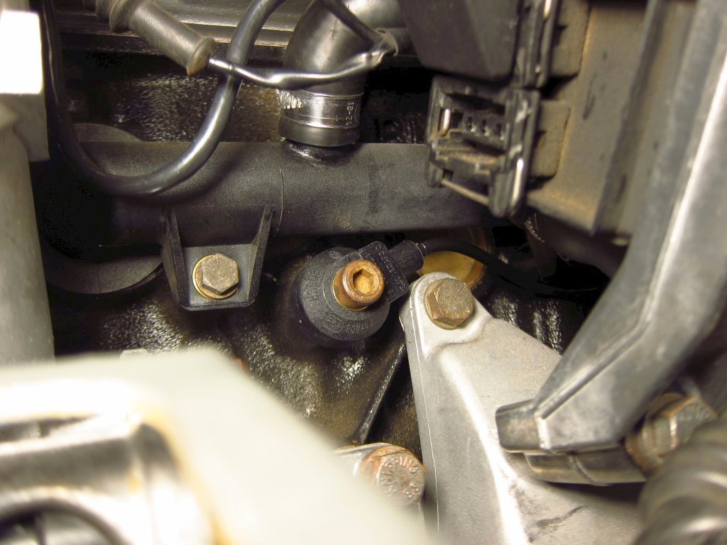
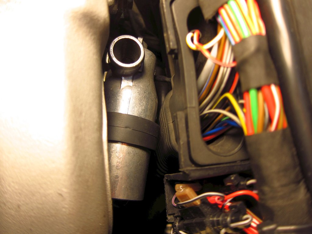
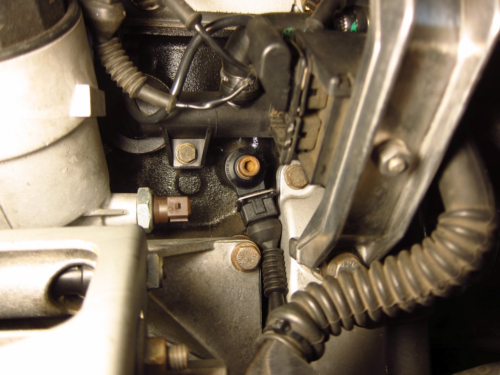
The other main thing that I started looking into, and determined that I have a problem with, is the front knock sensor. If you have never handled one before (like me), they are a lot bigger than you might think. Additionally, the ones I bought are even larger because they have the 2-pole plug molded into them, at a slight upward angle. The stock ones have the same size body, but no giant plug (or receptacle that needs to also fit onto it). Here's the existing boss where the front knock sensor goes. Thanks to the engine mount arm, water pipe, alternator mount bracket and oil pressure switch, it is pretty crowded in the area.
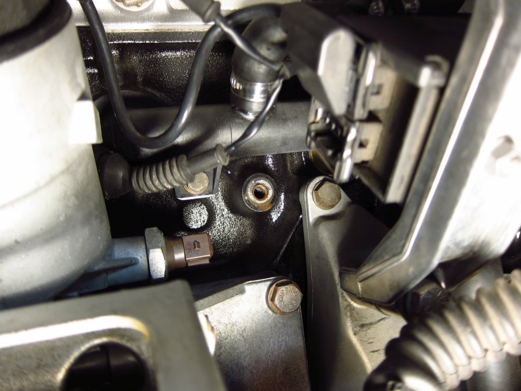
The only remotely plausible way to get the sensor + plug + boot in there is to position it like this. It is not jammed against either of the brackets, but there is at best 0.5mm of wiggle room. If I skipped the rubber boot and just used some wire seals instead, I think that it would likely be OK, but I really would prefer not to skip the boot since I have to tie the cable's shield to one of the terminals and don't want it exposed.
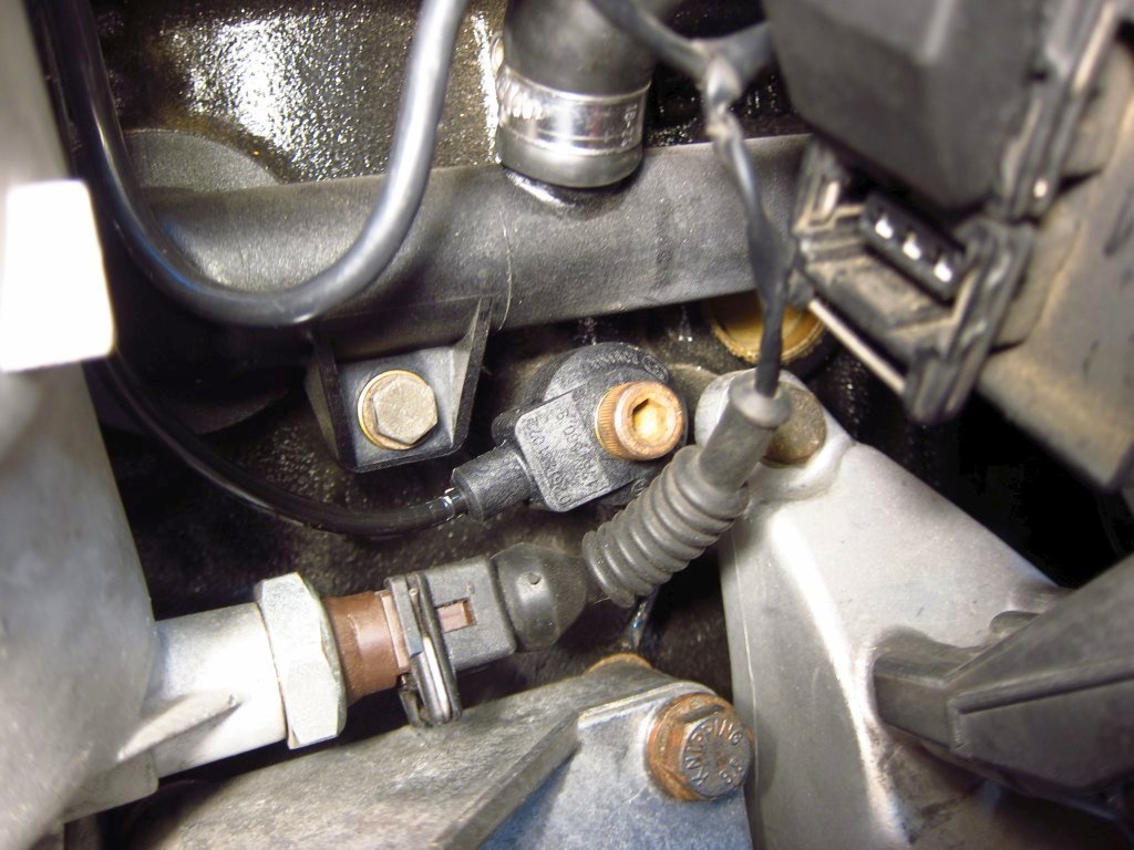
Furthermore, the oil pressure + temperature sensor is fairly large thanks to its connector, and since I am going to skip machining the oil filter housing and just use an M12 to M10 adapter fitting, the sensor will stick out even further than the pressure switch. Boot or no-boot, I don't think that the knock sensor can go here.
If I wanted to have the right amount of clearance for it, it would need to point this way, and the oil sensor could not possibly go here.
So that brings me to a decision between 2 options.
Option 1) Install the oil sensor in the back of the head where there is an M12 plug which I think (still not sure, trying to confirm) is for the head's main oil gallery. There is enough room between the head and firewall that the sensor, adapter and connector will fit fairly well. This way, I can keep the knock sensors I have and use them.
Option 2) Put the oil sensor in the oil filter housing, but get stock M42 knock sensors. I assume that the sensors themselves are either approximately the same as the ones I have, or at the very least tuned approximately right to work with my bore size (87.5mm, vs 84mm stock). The stock sensors are a lot more compact since they just mold the wire in and have the connector at the end of the small harness (same connector as the sensors I have too). In fact, the Bosch branded stock ones are a little cheaper than the KS4P sensors I already have, which is a big plus. I am 99% sure that these will enable everything to fit in there, with the only drawbacks being that the integrated harnesses will make things a little cluttered and these will probably become NLA at some point.
That's it for today. Progress is going to be a little slow as I make measurements and finalize positioning for things, but at least it all looks fairly plausible at this point.
Leave a comment:
-
No worries man, despite the OCD that oozes out in my posts, I am not all serious up in here or anything. Half the fun is shooting the shit about random technical stuff. If I can get someone stoked on electrical engineering and learning new things, then it just makes the whole thing better.
Regarding info about the OEM traction control systems, I would be extremely surprised if there was much in the way of detailed, practical info. But then again, it seems like there is always someone out there who decided to take apart XYZ and tell everyone how it works. Now I am thinking that it might be a cool little side product to make and sell an E30 wheel speed conditioner board that enables MS41 to apply its limited traction control...Leave a comment:
-
I've hardly looked into this, and I probably won't for at least another year. I haven't really looked into how I would compare, but I'm somewhat aware of Teensy (and the 3.3v "problem") just from speeduino research.
I haven't done a whole lot with microcontrollers, just a basic C course, a second year "intro to circuits" course, and a design class where we were let run amok.
I think before I do anything, I'll look at OEM setups since there must be a few good resources out there for it, but again it'll probably be a while before I get to it.
In the meantime I'm pretty content to follow along with your build, I don't want to sidetrack your thread.Leave a comment:
-
I second everything BMWman said - and nice thing about an MCU is you can trivially add some digital filtering to help with rejecting any noise, or hell, even integrate an accelerometer and go a more OEMish route. I would also especially stress going with something like the teensy over the Arduino.Leave a comment:
-
Got it. If you want to measure frequency accurately, you'll want to run with a microcontroller that has input capture hardwware. Regular Arduinos only have one channel. Check out the Teensy 3.2. It is the cost of an Arduino, smaller and WAY more powerful. There is a free library for it called freqMeasureMulti that greatly simplifies hardware driven frequency measurement, and the 3.2 has numerous input capture channels. You have to make sure to use the proper pins, but it'll make highly accurate measurement of all 4 wheel speed signals very easy. The only downside is that it is a 3.3V device. It'll handle 5V inputs fine, but you will need to make an output buffer to provide a 5V signal to the MS41. There are lots of commercial ICs for voltage level translation, and ti si fairly easy to do with some FETs and stuff too.
I'm not sure how much you've worked with microcontrollers, specifically for frequency measurement, so I won't dump too much info just in case you have done a bunch of it. If not, then it's a slightly tricky thing to do well (far less simple than measuring an analog input) and I can give you some pointers. Let's just say that trying to run a main loop to repeatedly check a logic level on a pin really fast is not the way to go lol.Leave a comment:

Leave a comment: