-
-
I'd guess that the difference in caps allowing air in or not may have something to do with the car having a charcoal canister or not having one. At least on late model US cars and the tourings I've had they've all had canisters, and they've all had the smooth plastic cap that appears to have some type of vent structure built in. Early cars seemed to have several different fuel cap styles, but I never looked in to why.
That said, the 80s were a crazy time for fuel setups, and if you ever want a laugh just look up the 325e (and some 325i models too apparently, but I've only seen it on ETAs) fuel supply line that runs through a heat exchanger in one of the refrigerant lines before going to the regulator.Comment
-
Thus, all E30 had a fuel tank ventilation system, regardless of the presence of an adsorber with activated carbon. It was put on cars to comply with Euro 2 environmental standards. For the USA, it was probably put on all cars. And in Europe, on cars without a carbon adsorber, the tank ventilation tube simply goes out into the atmosphere on the left side near the tank, without any valves.
Yes, I know about the "fuel cooling" option) For southern countries. I saw it on sale on ebay as far as Australia...far away.. ) But a rather dangerous thing - fuel hoses on clamps near the exhaust manifold! )Comment
-
Collection_72. ETK_41_Body. Simultaneous locking (driver's lock).
And again about the locks... I already wrote about the fact that it was not easy to find an entire driver's lock. The new lock was also rejected - they are no longer available. Therefore, I continued to search at flea markets and junkyards, and I still managed to find the cylinder of the driver's lock for the central lock. On the fourth try... Almost intact... :) The locking shank was cracked, but the main thing is that the lever is intact!

I wanted to simply rearrange the entire lever on my already-picked lock, but it turned out that not everything is so simple. Both of my broken locks had a roller bearing on the lever and the one I found had a ball bearing. So, they are at least of two types.
Accordingly, other details of the lock are also different. It can be seen in the photo.

The bearing washer is on the left for the ball bearing, on the right for the roller bearing.

The washer with a spring also has minor differences in the retainers.

And most importantly - different grooves on the lock cylinder itself! Left for ball bearing, right for roller bearing.

So, simply repositioning the lever will not work - all the details of the locks are different.

In addition to the locking shank and springs - here I was lucky, they are the same. So I had to change this lock under my own key, and rearrange the entire shank from my lock on it. I already have experience, so I did it quickly and without problems.

But, apparently, someone has already tried to open this lock with a screwdriver - that's why I had to change the decorative cover as well. I did not remove it on other locks. It is fixed with a core, and under it there is a curtain of slots for a key and a microscopic spring on the axis. Therefore, you need to remove it very carefully so that the spring does not fly out. I only miraculously did not lose her.

And installing it was even more difficult. Although, in fact, everything is simple - we insert the axis with the spring exactly like this:


We insert the curtain into the grooves, pressing the spring with it and hold it with a screwdriver. Now you need to somehow put the cover on the cylinder, and at the same time, so that the spring does not fly out together with the curtain! I struggled for probably 20 minutes... Then I found a working option - we insert the key into the cover (in the background of the photo):

Then we insert the key with the cover into the cylinder, and press the curtain with the spring with it. Now you can lower the cover on the key and fix it with the core. You need to turn not on the old marks, but in other places. There are no photos, because all hands were busy. :)
After several attempts, everything worked out - the cover is in place, and the blind moves normally with the key.
Next, simply assemble the lock with your own key, I already wrote about it - it is not worth repeating. The castle is ready.

The lock is assembled with heating.

We install a lock with a bracket, fix it with a heated bracket. Then we install the end of the key, connect it to the door wiring and fix the wiring in clips. Doing this is not very convenient, but in fact, everything is similar to what I previously described for the right door.

The driver's lock for the central lock is installed.

It remains to install the magnetic alarm lock, but I will write about this later in a separate topic.

So, now all the locks are installed, but the driver's lock works VERY tight and hard... If the passenger door lock opens and closes with a slight movement of the key, it takes a lot of effort to turn the key in the driver's door, after which it clicks loudly... That's probably why they're all already broken...and I think this lock won't last that long either... I don't know what can be done about it, and should it be...? I may have to return the modern alarm unit with remote control locks...
P.S.
An addition to the previous addition :)
I did manage to find the correct 85-87 lower engine bay shield.

Already washed it completely, it needs to be repaired a little more.
Now everything will be there as it should be.Comment
-
Collection_73. ETK_52_Seats. Seat heating.
I will continue about the wiring. So, the main wiring, the wiring of the "electric package" and the wiring of additional options have been laid, now you need to connect it all.

I will write about the wiring of each option separately. But, since the interior has not yet been assembled, I will add about the installation of some blocks and buttons later in separate entries.
I'll start with the seat heating wiring.
This is the last subdivision of the large ETK section Seats
For the E30, heating was available only for the front seats. Kits are different for regular and sports seats. They also differ in the type of seat upholstery - fabric or leather.
Retrofitting set of heated seat Pd

I also added heating to the rear seats - by analogy with the E32 and E34.
But first about the front ones.
Seat heating

Part No. 1 - seat cushion heating element - 2 pcs.
Detail #2 - seat back heating element - 2 pcs.
Both elements differ in the type of seat and its upholstery. I have installed elements for the leather sports seats of the convertible (64 11 1 380 687, 64 11 1 380 688) - I managed to buy them new once.

Part No. 3 - seat heating switch (61 31 1 366 464) - 2 pcs. - on the left in the photo. On earlier machines, buttons with a green backlight were installed - in the photo in the center. On the right is the E32/E34 button.

Part No. 4 - relay (61 31 1 373 588) - 1 pc. I already wrote about the relay earlier, but I will clarify - it is a K5 relay. It is also necessary to install fuse No. 16 with a rating of 15A.

Part No. 5 - seat heating wiring (61 12 1 380 484) - 1 pc. Of course, I checked all the wiring and rewound it.


1 - the power connector, connects to the connector of additional options C302 on pins T and U. Actually, only one pin U is used. The wire from adjusting the brightness of the backlight of the devices comes to pin T, but it is not used. I still did not understand why it is there... By the way, I updated my table on pinout C302.

2 - "ground" wire, screwed at point G200.

3, 4 - connectors for heating elements, left and right seats.

5, 6 - connectors for heating buttons, left and right seats.

Part No. 6 - bracket (52 10 1 916 175) - 2 pcs. It is installed under the seats on the springs of the frame to fix the connectors of the heating elements.

Part #7 - terminal D=9/B=4 (61 13 1 351 045) - 1 pc. To fix the wiring, but in which place, I didn't understand... that's why I didn't put it...
Part #8 - screed L=292MM/B=4.8MM (61 13 1 377 134) - 4 pcs. For additional fixation of the wiring to the main harnesses.
I made the wiring for heating the rear seats myself. It was based on a universal set of seat heating and modified according to the ETM scheme and E32/E34 buttons.


1 - power connector, connects to the additional options connector C302 on pin P. This pin is unused and empty from the factory. I added it in parallel with the U pin for the heated front seats. You still need to pick up a plastic case with the necessary "code" for it
2 - "mass" wire, screwed at point G300.
3.1, 3.2 - connectors for heating elements of the pillow and the back of the left rear seat.
4.1, 4.2 - connectors for heating elements of the pillow and the back of the right rear seat.
5, 6 - connectors for heating buttons, left and right rear seats.

7 - button illumination power connector, connected to the rear ashtray illumination lamp.
8 - the "ground" wire of the backlight of the buttons, screwed to the pin of the console.
So, the wiring is laid along the left threshold, to the gearbox tunnel and under the back seat. We connect the power connectors in C302. The front ones are on the T and U pins, and the rear ones are on the P pin.

The button connectors are placed on the gearbox tunnel, and the heating element connectors are placed under the left and right front seats.

Then they will come out through special slots in the carpet, connected to the seats and fixed in special brackets (#6). These are my old photos. It is probably here that you will need to add a terminal and tie rods (#7 and #8), but so that it does not interfere with adjusting the position of the seat.
[img width=800 height=600]https://i.ibb.co/Xtymmqg/01.jpg[/img]

Connectors for heating the rear seats are placed under the rear seat. Then the cushion and the back of the seat will be connected to them.
[img width=450 height=600]https://i.ibb.co/25Gtfzz/20230509-164347.jpg[/img]
The connectors for the buttons and their illumination are brought out to the gearbox tunnel and connected to the lamp of the rear ashtray. For this, I made a special connector there, I will show it later.

After the interior is fully assembled, the heated seats will look like this (for now, this is my old photo):

I won't be driving this car in the winter, but all seats are heated! ;)
P.S.
In fact, a lot has already been done - I will somehow write about it little by little...Last edited by The_Glory; 10-13-2023, 04:24 AM.Comment
-
Collection_74. ETK_65_Security alarm system
The next option, quite rare for the E30, is a standard alarm system.
In ETK, this unit is in the general section Audio, navigation, information systems
More modern alarm systems with remote control from the remote control were already available on cars of the last years of production.
But I have the earliest version of it, with a magnetic key - S301 Anti-theft alarm.
Security alarm system
I will say in advance that I also plan to install a standard immobilizer - S900 Recognized immobilizer by AZT/TÜV. But this will probably be the last thing.
Therefore, the alarm system can be installed separately or together with the on-board computer - they have a common part of the wiring under the hood and the ECU. What's more, the signaling ECU is also suitable for BC, but the BC ECU is not suitable for signaling. Therefore, in this topic I will partially describe the installation of the on-board computer, at least its wiring. And later there will be a separate entry about him.

Standard alarm set (#1):

The photo is missing several parts that are already installed on the car - the main wiring (#13), diode wiring (#9). Also, the wiring of BC (#15) is not shown - there will be a separate entry about it later.
Part #2 - signaling ECU (65 75 1 386 605) - it is also used for BC.
Part No. 3 - plastic nut (61 13 1 372 722) - 1 pc.
Part No. 4 - self-tapping screw ST6,3X25-C-Z2 (07 11 9 916 973) - 1 pc. Parts #3 and #4 for attaching the ECU to the body. But for some reason I had no holes or pins there at all. Perhaps it depends on the year of manufacture of the car. So, I made a mount for the restyling bracket, and attached the ECU to it with two self-tapping screws (#4).
Part No. 5 - magnetic lock with locking bracket (65 75 1 368 904) - 1 pc. Installed on the driver's door.
Part No. 6 - cover of the lock with an LED (65 75 1 368 903) - 1 pc.
Part No. 7 - rubber gasket (65 75 1 368 912) - 1 pc.
Part #8 - magnetic key (65 75 1 380 684) - comes in two types, but the principle of operation and its coding are similar.

Part No. 9 - control lamp (65 75 1 369 412) - a duplicate LED, which is placed under the rear license plate.

I have already mentioned it before, when installing the overlay under the number. By the way, for some reason there is no place for its installation in the overlay - I had to mark and drill it myself.

Part No. 10 - sound signal with two mounting plates (61 33 1 367 358) - 1 pc. It is installed near the fuse block. After restyling, it is installed behind the left fog lamp. I have exactly such an option.
Part #26 - horn bracket (61 33 1 380 019), or (65 75 1 385 783) after restyling.


Part #11 is a plastic (65 81 1 373 714) or metal (65 75 1 385 907) shield after restyling.
Part No. 12 - self-tapping screw ST6,3X16-C-Z2 (07 11 9 916 966) - 1 pc. For attaching a sound signal. Perhaps this is a mistake, or it is for restyling. My bracket (#26) has a bolt-on mount.
Part No. 13 - main alarm wiring (61 12 1 375 608). I already installed it on the car along with the other wiring.

1 - connector of the alarm ECU
2 - connector for wiring #16 (or BC wiring)
3.1, 3.2 - corresponding connectors to the door stop
4 - connector for wiring "electric package"
5 - "mass" G300 under the rear seat
6.1, 6.2 - corresponding connectors for heating the rear glass
7.1, 7.2 - corresponding connectors to the end of the trunk
8 - connector to the rear LED
Part No. 14 - magnetic lock cable (61 12 1 380 488) - is inserted into the door connector of the driver's door.

1 - connector of the alarm ECU
2 - into the door connector C405
Part No. 15 - alarm wiring (61 12 1 375 606) - to the engine ECU (or BC wiring). In the photo, it is marked with the letter A.
Part No. 16 - underhood signaling wiring (61 12 1 375 606), similar to BC. In the photo, it is marked with the letter B.

Connection of two wires.

A1 - connector for underhood wiring #16 B1
A2 - connector for underhood wiring #16 B2
A3 - connector to the alarm ECU
A9, A10 - corresponding connectors for the Motronic engine wiring ECU
It is likely that in the case of an alarm installation without an on-board computer, this wiring had only these connectors. Other connectors of this wiring are used only for the on-board computer. I will write about them in the relevant topic.
B1 - connector for wiring #15 A1
B2 - connector for wiring #15 A2
B3 - connector to the alarm ECU
B4 - connector C302 pin H
B5 - "mass" G200 under the steering column
B6 - connector for alarm wiring No. 13, connector 2
B7 - connector to the end of the hood
B8 - connector to the external temperature sensor
B9.1, B9.2 - audio signal connector
Part No. 17 - hood end cap (65 75 1 370 492) - 1 pc.
Part No. 18 - hood end bracket (65 71 1 378 069) - 1 pc. It is placed on the left bracket of the hood, I already mentioned it earlier in the topic about the hood.
Part No. 19 - driver's door central lock drive (51 26 1 375 111) - 1 pc. I don't know how it differs from a regular drive, but everything worked for me on a regular drive as well.
Part No. 20 - drive mounting bolt (51 26 1 375 979) - 2 pcs.
Part No. 21 - bracket D = 13MM (61 13 1 371 074) - 1 pc. For fixing the external temperature sensor connector.
Part No. 22 - clip D=16.8MM (12 52 1 276 147) - 1 pc. To fix the sound signal wire.
Part No. 23 - terminal D=15/B=4 (61 13 1 353 866) - 1 pc. For fixing the wire of the external temperature sensor.
Part No. 24 is a clamp for a microswitch (65 81 1 377 861). I'm not sure, but it's probably the same part as #18.
So, we begin to install the alarm system.
The main wiring (#13) is already laid along the left door sill, under the rear seat, and in the trunk to the rear license plate. It is also wound along the rib in the trunk lid, and connected to the terminal with a 7.1 connector. The main wiring of the terminator is connected to the corresponding connector 7.2.

In the body, the factory does not provide a hole for the installation of an alarm control lamp under the rear license plate. But in the original EBA instructions, there is a diagram for marking the hole, according to which it is necessary to drill it yourself. We mark and drill. This is my old photo:

Insert the LED into the hole and connect it to connector 8.


It has everything in the trunk. Let's go to the front part. We pass wiring No. 16 through a special hole in the rubber insert of the motor shield.

Next, we lead the wiring to the fuse block and lay it along the left wing behind the left fog lamp. From the bottom of the platform, we screw the sound signal into the provided holes. Pre-connect connectors B9.1 and B9.2 to it, and fix the wire with clip #22.


The sound signal is closed by a protective shield, which is attached to a pin on the spar with a plastic nut and two bolts in the holes in the platform.

The connector of the external temperature sensor B8 with the sensor is brought out under the left fog lamp and we fix the wire to the shield with clip #23.

By default, it is inserted into a special hole in the front spoiler (or into the air duct after restyling). But I will have a BBS apron installed instead of the standard spoiler, which does not have this hole. Therefore, I will then look around the place, how it is better to fix it there.
Places of attachment of the sound signal and shield on the site - top view:

Near the fuse block, connect the terminal of the hood No. 17 to connector B7. With the help of bracket No. 18 (and/or No. 24), we fix the end piece on the left bracket of the hood locks.

We fasten the bracket with the terminal.

The stop is set. This is everything under the hood.

Let's go to the salon.
We connect connector 1 of wiring #13, connector 1 of cable #14, connector A3 of wiring #15, connector B3 of wiring #16 to ECU signaling #2. We connect black connector B6 of wiring #16 and black connector 2 of alarm wiring #13.
Connector B4 of wiring No. 16 is connected to the connector of additional options C302 on pin H.

We fasten the ECU block with two self-tapping screws to the plastic bracket installed behind the instrument panel.
We fasten the "mass" terminal B5 of wiring No. 16 at point G200 under the steering column.

Signal wiring connectors No. 13 3.1, 3.2 and 4 are brought out to the niche of the left speaker. We connect connector 3.1 to the terminal of the driver's door, and connect the main wiring of the terminal to the corresponding connector 3.2.

Connector 4 is connected to the corresponding wiring connector of the "electric package" in the speaker niche.

We connect the corresponding wiring connectors No. 15 and No. 16 - A1 with B1, and A2 with B2.

Wire No. 15 is laid to the right, connectors A9 and A10 are connected in a gap to the corresponding connectors of the ECU Motronic engine wiring. I haven't installed the motor wiring yet, so I will do that later.

These connectors are used to disconnect power from the Motronic ECU. If for some reason you will not have wiring #15 connected to wiring #16 (A1 from B1, and A2 from B2.), or there will be no underhood wiring at all, then these connectors do not need to be connected - otherwise the engine will not start.
We go to the back of the salon.
We fasten the "mass" terminal 5 of wiring No. 13 at point G300 under the rear seat.
It remains to connect a connector that is not entirely clear to me - to the heating of the rear window. Why is it - I don't understand... Maybe the alarm will work when the heating filaments are broken, if you break the rear window... I won't experiment. :)
So, we connect connector 6.2 of wiring No. 13 to the left contact of the rear window heating (the glass has not yet been installed).

And to the corresponding connector 6.1, we connect the glass heating connector from the main wiring.

That's all for the cabin.
All that remains is to install the magnetic lock in the driver's door and connect it.
We lay cable No. 14 to the niche of the left speaker.

We insert its connector 2 into a special hole in the door connector C405 and fix it with latches.

We install the connector and connect the corresponding door wiring connector to it. It is not very convenient to do this, but in the end, I did it.

Of course, the factory does not provide a hole for installing a magnetic alarm lock in the door. But in the original EBA instructions, there is a diagram for marking the hole, according to which it is necessary to drill it yourself. We mark and drill. This is my old photo:

We get such a neat opening (this is also my old photo):

Since all the doors were replaced during the body work, it was necessary to re-drill such a hole in the other doors. I decided that it would be easier if the craftsmen made the hole immediately on site - I gave them the same diagram with dimensions from the EBA. I did so in vain... this is what came out of it...

...*??%№№"""**??:%%; I had no other words when I saw it....well HOW SO??? A vivid example of folk wisdom - "do you want to do something good - do it yourself!" (c)
Fortunately for me, the new rubber gasket covers this shame - although that is a little comforting...
In the same way, we lead the connector of the door wiring cable to the magnetic lock into this hole (call it a hole - the tongue does not turn).

We insert the lock into the hole from the middle, put a rubber gasket and an overlay with an LED on the outside. Then we fix everything in the assembly from the middle with a locking clip in a special groove in the lock. I haven't installed the lock yet, as I forgot to paint its cover matte black. Will paint later, with other parts together.

The LED connector and the door wiring cable connector connect to the lock. It will look like this (my old photo again):

So that there is no doubt that the key is magnetic! ;)
A regular security alarm system is installed.
If you're wondering how it works, I made a video last time:
[MEDIA=youtube]LyveS8qmx34[/MEDIA]
View: https://youtu.be/LyveS8qmx34
[MEDIA=youtube]vQHqyZiRz34[/MEDIA]
View: https://youtu.be/vQHqyZiRz34
Next time I will probably write about the on-board computer.Comment
-
Assembly_75. ETK_62_Board computer
So, as promised, we will talk about the on-board computer.
In ETK, this section is in the general section Instruments
BC sets are slightly different for cars before restyling and after restyling. The main differences are in the wiring and location of the siren.
I have a combined option :) Interior wiring before restyling, and underhood wiring after restyling. Moreover, this kit was removed from one car in the USA. Perhaps this is a feature of the configuration for this market, because on European cars, these wirings are not very compatible, without additional modifications. And I connected everything without problems.
On-board computer
So, I remind you that I already have a factory alarm system installed. In this case, the BC is an "appendix" to it - they share the underhood part of the wiring and the ECU. What's more, the signaling ECU is also suitable for BC, but the BC ECU is not suitable for signaling. Therefore, in this topic I will describe only the installation of on-board computer parts that do not relate to signaling (the left part of the diagram):

On-board computer:

The photo is missing several parts that are already installed on the car - interior wiring (No. 13), underhood wiring (No. 14). The ECU (#7), steering wheel switch (#12), and siren (#20...#25) are also not shown.
Part #1 - on-board computer unit (65 81 1 374 917) - for the US market, with inscriptions in English.


Part #2 - encoder (65 81 1 373 698) - is mainly responsible for the accuracy of fuel consumption indicators.

According to the table - this is 3-8 Typ - for 325e. Not exactly what you need for a 325i, but okay :)

The photo also shows the timer switch for controlling the autonomous heater (Webasto).
Part No. 3 - button illumination lamp 1.2W (62 11 1 368 299) - 1 pc.
Part No. 4 - screen illumination unit (65 81 1 375 461) - white case with two soldered lamps. To replace the lamps, the BC is simply pulled out of the housing.

Part No. 5 - plug (65 81 1 374 938)
Part #6 - screw M3X10 (07 11 9 907 605) - 4 pcs.
Part No. 7 - signaling ECU (65 75 1 386 605) - it is also used for BC. In the version without alarm, the ECU (65 81 1 373 726) is used - without a connector for the cable of the magnetic lock.
Part No. 8 - self-tapping screw ST6,3X25-C-Z2 (07 11 9 916 973) - 1 pc.
Part No. 9 - plastic nut (61 13 1 372 722) - 1 pc. Parts No. 8 and No. 9 for attaching the ECU to the body. But for some reason I had no holes or pins there at all. Perhaps it depends on the year of manufacture of the car. So, I made a mount for the restyling bracket, and attached the ECU to it with two self-tapping screws (#8).
Part #10 - gong (65 81 1 376 047) - for the US market, with two connectors. One for BC, the other for the driver's seat belt warning light. European machines have only one connector for BC.

Part No. 11 - bracket (62 13 1 373 572) - gong holder, which is placed in the steering panel.

Part No. 12 - turn signal switch (61 31 1 375 186) - for BC has an additional button on the end, which cyclically duplicates the pressing of buttons on the BC

Part No. 13 - interior wiring of the on-board computer (61 12 1 373 727). In the photo, it is marked with the letter A.
Part No. 14 - underhood wiring of the on-board computer (61 12 1 373 729), similar to the alarm system. In the photo, it is marked with the letter B.
Connection of two wires.
A1 - connector for underhood wiring No. 14 B1
A2 - connector for underhood wiring #14 B2
A3 - connector to the signaling ECU (or BC)
A4 - gong connector
A5 - connector to the turn signal switch
A6 - connector to the yellow connector C3 of the instrument panel
A7 - connector to the on-board computer unit
A8 - connector for an autonomous heater (Webasto)
A9, A10 - corresponding connectors for the Motronic engine wiring ECU
B1 - connector for wiring #13 A1
B2 - connector for wiring #13 A2
B3 - connector to the signaling ECU (or BC)
B4 - connector C302 pin H
B5 - "mass" G200 under the steering column
B6 - connector for alarm wiring
B7 - connector to the end of the hood
B8 - connector to the external temperature sensor
B9.1, B9.2 - siren connector
Part No. 15 - external temperature sensor (65 81 1 385 337). In my case, the sensor is different - restyling. Therefore, the details of its fastening No. 16...No. 19 and No. 22, No. 24 are not used. The fastening described above, in the section on signaling, is used.
All details of the siren and its fastening are also similar to the alarm system.
Part No. 20 - sound signal with two mounting plates (61 33 1 367 358) - 1 pc. It is installed near the fuse block. After restyling, it is installed behind the left fog lamp. I have exactly such an option.
Part No. 21 - a plastic (65 81 1 373 714) or metal (65 75 1 385 907) shield after restyling.
Part No. 23 - self-tapping screw ST6,3X16-C-Z2 (07 11 9 916 966) - 1 pc. For attaching a sound signal. Perhaps this is a mistake, or it is for restyling. My bracket (No. 25) has a bolt-on attachment.
Part #25 - horn bracket (61 33 1 380 019), or (65 75 1 385 783) after restyling.
So, we start installing the on-board computer.
Since the underhood part is similar to the alarm system, I will simply repeat everything:
We pass wiring No. 14 through a special hole in the rubber insert of the motor shield.
We lead the wiring to the fuse block and lay it along the left wing behind the left fog lamp. From the bottom of the platform, we screw the sound signal into the provided holes. Pre-connect connectors B9.1 and B9.2 to it, and fix the wire with a clip.
The sound signal is closed by a protective shield, which is attached to a pin on the spar with a plastic nut and two bolts in the holes in the platform.
The connector of the external temperature sensor B8 with the sensor is brought out under the left fog lamp and we fix the wire to the shield with a clip.
By default, it is inserted into a special hole in the front spoiler (or into the air duct after restyling). But I will have a BBS apron installed instead of the standard spoiler, which does not have this hole. Therefore, I will then look around the place, how it is better to fix it there.
Places of attachment of the sound signal and shield on the site - top view:
Near the fuse block, connect the terminal of the hood to connector B7. The end of the hood is used only for signaling. When installing the on-board computer separately, it is not used. With the help of the bracket, we fix the terminal on the left bracket of the hood locks.
We fasten the bracket with the terminal.
The stop is set. This is everything under the hood.
Let's go to the salon.
We connect the alarm wiring connector, magnetic lock cable connector, A3 wiring connector #13, B3 wiring connector #14 to the alarm ECU. We connect the black connector B6 of wiring No. 14 and the black connector of the alarm wiring.
Connector B4 of wiring No. 14 is connected to the connector of additional options C302 on pin H.
We fasten the ECU block with two self-tapping screws to the plastic bracket installed behind the instrument panel.
We fasten the "mass" terminal B5 of wiring No. 14 at point G200 under the steering column.
We connect the corresponding wiring connectors #13 and #14 - A1 with B1, and A2 with B2.
The photo also shows the gong and turn signal connectors.
We connect the gong to connector A4.

We install the turn switch

But we connect the blue A5 connector to it.

The turn signal switch for the US market does not have a connector for parking marker lights - this option was not available in the US. Therefore, this white 2-pin connector of the main wiring remained unused. Maybe later I will find a European turn signal switch for BC, then I will also connect the parking marker lights.
Connect the yellow connector A6 to the yellow connector C3 of the instrument panel when it is installed.
We screw the BC block directly to the frame - without an adapter, which is used only for the clock.

In the assembly, we install the frame in the torpedo. It is probably almost impossible to fix the BC unit without removing the entire frame.

We lay the wiring No. 13 on the right, connect the green connector A7 to the unit of the on-board computer.
The white small connector A8 is the connector for the autonomous heater (Webasto). I don't have it yet, so it remains inactive.
Connectors A9 and A10 are connected in a gap to the corresponding connectors of the Motronic ECU of the motor wiring. I haven't installed the motor wiring yet, so I will do that later.
These connectors are used to disconnect power to the Motronic ECU using the on-board computer's CODE function. If for some reason you will not have wiring #13 connected to wiring #14 (A1 from B1, and A2 from B2.), or there will be no underhood wiring at all, then these connectors do not need to be connected - otherwise the engine will not start.
That's it for installing the on-board computer.Comment
-
i really enjoy reading and watching you build this car! lots of knowledge that I myself have also been able to use from your thread.
Can't wait to see more posts from you!BMW E30 M3 - S50B32
www.e30.isComment
-
Collection_76. ETK_65_Details of the audio system (part 1 wiring)
Let's return to the ETK section Audio, navigation, information. systems
So, section Audio system details

Now I will briefly write only about the top E30 audio wiring "Soundsystem" (detail #4 on the diagram), and I will write about the whole set after the interior is assembled. I managed to find the "Soundsystem" wiring for the Touring - it differs from the sedan in the connectors and wire lengths for the rear speakers and the "ground" terminal. Therefore, you will have to connect the rear speakers through home-made adapters, but more on that later. These are the connectors for which it turned out to be very difficult to find the corresponding "folders".


The wiring was in very good condition....but with the effects of early 2000s mp3 audio tuning. - with a cut-off connector for the standard radio... I had to take it from the donor audio wiring E46 and install it on my own wiring.

I also unfoamed the connectors of the radio and the "Soundsystem" amplifier - maybe someone will need it too.

I added two wires to the wiring related to the operation of the telephone - TEL MUTE, muting the sound during an incoming call to a standard telephone, and the I-BUS bus. I don't know if the last one will be useful or not, but just in case! ;) I will write more about this in the corresponding entry about the phone.
So, as a result, I have the following "Soundsystem" wiring:

1 - 16-pin radio connector (for later models, after restyling)
2 - electrical antenna (and audio amplifier) power management connector
3 - speed signal connector for volume control (any of the three identical pins in the green connector on the instrument panel C6 (Tempo)
4.1 - connector BATT+ constant power supply of the amplifier from the battery - C302 (H)
4.2 - connector corresponding to 4.1, for parallel connection of on-board computer wiring - C302 (H)
4.3 - radio power connector:
BATT+ constant power from the battery - C302 (V)
Backlight - C302 (W)
ACC+ power supply from ignition - C302 (X)
GND mass - C302 (Y)
5.1, 5.2, 5.3 - front left speaker and tweeter connectors
6.1, 6.2, 6.3 - connectors for the front right speaker and tweeter
7 - connector for connecting a telephone (TEL MUTE and I-BUS) - added independently.
8 - rear left speaker connector
9 - rear right speaker connector
10 - ground terminal
11 - audio amplifier connector
We connect the power connector of the radio 4.3 to the connector of additional equipment C302 (pins V, W, X, Y), and the power connector of the amplifier 4.1 (pin H).
But the on-board computer is already connected to pin H. Therefore, we remove it, connect the amplifier 4.1 in its place, and connect the on-board computer connector to the parallel corresponding connector of the amplifier 4.2.

The speed signal connector 3 is connected to the green connector of the instrument panel.

Connector 1 of the radio and connector of power control of the electric antenna 2 are brought to the radio.

We lay the connectors of the front speakers to the niches and connect the blue connectors 5.3 and 6.3 to the door wiring to the tweeters. The other two connectors are connected to the speakers.

Similarly on the right side.
Connector 7 is output to the central console, to the phone - I will write about this in a separate topic.
We lay the wiring along the left threshold to the rear part, and bring out the connectors of the rear speakers 8 and 9. As I already said, I have wiring from the Touring, so I will have to install adapters-extensions. At least on the left side for sure.


We pull the wiring into the trunk. Apparently, the Touring has a special contact for "mass", which the sedan does not have. Therefore, in order not to extend the wire to the G300 terminal, I had to screw terminal 10 into the factory hole on the body bracket.

Audio amplifier jack 11 is taken out for the left loop of the trunk - the amplifier will be installed there.

I will write about the installation of speakers, radio and amplifier in the second part, when the interior is already assembled.
The next entry will be about an electric antenna or a telephone.Comment
-
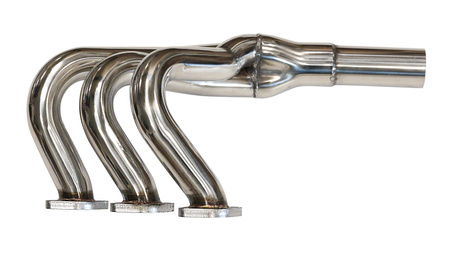
Turbo Works Equal Length Manifold and Other Toys
I'm already tired of writing about that wiring... I'd rather show off the toys I've bought lately! :)
For a long time I wanted to install an equal-length collector - not so much for "sport" as for beauty! :) And recently a friend was selling a new set at a good price, so I decided to buy it. Everything, the entire production system will have to be done practically from scratch. Unless, only the old double stronger can be left... we'll see...
So, the Turbo Works manifold is a Polish manifold, most likely made in China! )) People say that this is a copy of Supersprint, but I don't know how true that is...

The set includes front and rear collectors, X-pipe, gaskets and screeds for thermal insulation. By the way, is thermal insulation mandatory or can it be installed without it? It's more beautiful without her! )))

In appearance, the quality of the pipes and welds is good, all flanges are flat on the plane.


I tried it on - it seems to be normal... Although one pin does not go through a bit... By the way, should you unscrew the old pins, or is it better not to touch them so as not to break them? Six pieces came out, and six more remained.

But replacing the oil filter will probably be a "special pleasure" now! :)

But beauty needs sacrifices! (with) :)

The "bonus" to the collector was actually a new, original short link from Z3M. Before that, I had its analogue, now it will be the original. I also started making a wooden pen with backlight.

I bought a couple more cassette decks - with vertical cassettes - I have one idea about them, but more on that later.


And some other little things - a friend printed some useful plastics on a 3D printer. By the way, I didn't take photos of all of them.

But a little electroplating - something I forgot last time.

These are the updates! ;)
Then again about the wiring.... )Comment
-
Collection_77. Phone (part 1 wiring)
For some reason, the ETK for E30 does not have a section on a regular phone, although this option was available, and in several variants. Installation of the telephone in the E30 is described in the EBA factory instructions and shown in the company booklets. I already wrote about this in detail before, so I won't repeat myself. I installed the GSM phone kit taken off the E38, so the setup is not exactly factory, but not by much. Now I will write only about the installation of the wiring, and after the assembly of the cabin I will write about the installation of the phone itself and the speaker system (hands-free).
So, the set includes power wiring for the telephone unit, direct telephone wiring, speaker system wiring and an antenna cable.
The power wiring of the telephone unit looks like this:

1 - power connector. By default, the phone's power supply is connected to the C103 connector, but I thought it would be more convenient to duplicate it from the radio's power supply to a separate connector:
BATT+ constant power from the battery - C302 (V)
ACC+ power supply from ignition - C302 (X)
2 - speed signal connector for volume control (any of the three identical pins in the green connector on the instrument panel C6 (Tempo)
3 - the connector of the front left speaker for the speaker system (hands-free) - the second pair of contacts
4 - the connector of the front right speaker for the speaker system (hands-free) - the second pair of contacts
5 - connector for connecting the phone to the radio (TEL MUTE and I-BUS). Muting the sound of music during an incoming call TEL MUTE also works on most standard E30 radios, and in order to display the number of an incoming call on the radio screen, you probably need to install newer models of radios that support I-BUS.
6 - connector for backlighting the phone buttons. I connected it to the backlight of the rear ashtray, with a separate connector, together with the backlight of the buttons for heating the rear seats.
7 - "mass" terminal G300
8 - phone ECU power connector
9 - phone ECU connector for hands-free system
10 - speakerphone microphone connector (hands-free)
Telephone wiring:

1 - phone ECU connector
2 - connector of the telephone ECU for the speakerphone system (hands-free). Connects to connector 9 of the previous wiring.
3 - phone ECU power connector. Connects to connector 8 of the previous wiring.
4, 5 - base and handset connectors
In addition, an antenna cable is connected to the ECU. Without an antenna, the phone may fail.
Phone ECU on a bracket with E38

The SIM card is inserted as a whole.

The ECU is normally installed on a special bracket on the rear left wing trim. But I installed it under the rear shelf because this ECU is much more compact than the older models. He became very good, as if he was there!


We connect the wiring and antenna cable.

By the way, about the antenna. A separate GSM antenna is used for the phone. But you can install an adapter to use one antenna for radio and phone. I don't know what it is called, but I found two such units and several telephone antennas. Even one more Soviet-made on a magnet! :)

There was also an idea to make a spaced antenna using the filaments of the rear window heating, as in the newer BMW models, but for this the heating would have to be physically separated into separate parts. Well, this idea was shelved, and the remote antenna block remained unused :)
But I did install the block for the radio antenna so as not to install a separate antenna for the phone. The VIMAR unit had a less attractive appearance, so I chose the KATHREIN unit, especially since the GSM antenna was also from this manufacturer.

Made a short antenna cable to it.


Installed and fixed together with the rear lamp control unit.

I connected the antenna cable of the phone and the radio. I will write about wiring the radio antenna separately.

In the cabin, I laid the power wiring along the left threshold and connected it to the separate connector from C302

I laid the telephone wiring under the back seat and through the checkpoint tunnel.

I fixed the wiring on the tunnel with tape. The connectors of the base and the tube were brought to the back of the console, and the microphone to the front. I will install them after assembling the interior.

Connectors of the speaker system (hands-free) are connected to the front speakers on the left and right. Speakers have two pairs of contacts - separately for music and phone. I will install them later as well.

For now, here's an old photo of my installed phone

But the video of his work
Next time I will write about the electric antenna.Comment
-
Where did you buy the exhaust manifold ?Comment
-
Well, I wrote - I bought it from a friend, because he changed his mind about installing it :)
And in general, here it is on the manufacturer's website:
Comment
-
Collection_78. ETK_65_Antenna accessories
So, about the antenna. There were several types of them - mechanical or electric, with different cables and connectors, different fasteners, with a chrome or black rod. I have already written about the installation of an electric antenna before, so I will write briefly, without unnecessary details and numbers.
Until 1985, antennas were with threaded connectors.
Antenna accessories

Detail #1 - mechanical antenna. We do not consider its details.
Item #3 - Hirschmann Auta 6000 powered antenna.
Detail No. 5 - chrome or black (shadow line) telescopic element.
Detail #7 - wiring and antenna cable. It can be with a threaded or plug-in connector for the antenna.
Item No. 8 - antenna connector adapter
Item No. 10 is a special key for attaching the antenna
Part No. 11 - the antenna fastening nut
Item No. 12 - antenna repair kit
After 1985, the antennas were with plug-in connectors.
Antenna accessories

Basically, everything is the same, but there are two types of antenna cable - with different connectors to the radio - "father" or "mother", for different radios.

Part No. 13 is a cable "father", for later models of radios.
Part No. 14 - "mother" cable, for earlier radio models (top left in the photo).
Adapters for both types of cable were also provided.
Part No. 8 - adapter "mom-dad" (65 12 1 394 202)

Part No. 16 - adapter "father-mother" (65 12 1 388 950)

Original adapters cost 18-20 Euro - unreasonably expensive, in my opinion. That's why I bought analogues at a price of 0.5 Euro. In addition, analogs are made in one housing, without additional cable connections - this is even better for the quality of reception.

The antenna itself is not in the photo - I could not find the Hirschmann Auta 6000. But kits were available for equipping in the accessories section.
It could be a set of mechanical antenna - we do not consider it.
Mechanical antenna

Hirschmann Auta 6000 electric antenna kit. In principle, the same as shown above.
Automatic antenna

Electric antenna set Hirschmann Hit Auta 5091. This is a more universal model that was installed on different brands and models of cars.
Automatic antenna

I managed to find just such an antenna, although not a complete set, and in a non-working condition. The antenna was repaired, cleaned, equipped with the original relay and wiring with a cable, a hose for drainage, made a bracket for its attachment instead of a universal mounting plate.

Briefly about the repair. Most likely, the telescopic element was replaced in the antenna, but it is a little shorter, so the extreme positions of the element did not coincide with the position of the limit switches, and the fuse constantly blew. We disassemble the case, remove the plastic covers, remove the gear from the engine so that the telescopic element can be moved freely by hand.

On the other hand, remove the rubber gasket and the limit switch cover.

The point is to choose the size of the sector that breaks the contacts in the extreme positions of the telescopic element. In words it is difficult, but in fact everything is simple - you move the telescope, count the revolutions of the gears, and mark the extreme positions. To increase the contact gap sector, I pasted a piece of black oracle - it works fine.

Next, for the antenna to work, you need a relay to reverse the polarity of the contacts, which was not included in the kit. On later models, it is already built into the antenna, and on this model, it is taken out separately. First, I made it from two standard relays according to the following scheme:

In theory, everything should work. But often, especially at the moment of starting the engine with the radio on, both relays did not work synchronously, but one with a delay of a fraction of a second. This was enough to cause a short circuit and blow the fuse. And when I ran out of original fuses, I stupidly installed a Chinese fuse - all the wiring of those two relays burned out, it's good that the car didn't burn down. I do not recommend this option.
I bought an original polarity reversal relay in a radio store and assembled it according to the manufacturer's original scheme.

Relay

unpinning

Scheme of work

In the wiring, I replaced the antenna cable for earlier radio models with a "mother" connector.

1 - connector of the antenna cable to the radio ("mother")
2.1 - antenna power control connector (turns on and off when the radio is turned on and off)
2.2 - parallel connector suitable for 2.1 (for powering the audio amplifier)
3 - connector for constant power supply of electric antenna C302 pin Z
4 - electrical antenna connector
5 - connector of the antenna cable to the electric antenna
I didn't have a regular antenna at all, so I had to make a hole in the wing to install it. The dimensions of the opening are specified in the EBA factory instructions.

By default, this antenna is attached with a universal mounting plate. I made a bracket for it - it is more reliable and neater in appearance. I am attaching the drawing, maybe someone will need it too.

The bracket is screwed to the antenna body in the hole provided there.
We connect the wiring and antenna cable to the antenna. By the way, in the previous topic I wrote about the antenna adapter. So in this case, we connect the antenna cable from the radio to the upper connector of the adapter, and connect the cable from the middle connector of the adapter to the antenna. The telephone antenna cable is connected to the lower connector.

We insert the antenna into the hole, put all the washers, spacers, rubber gasket, and decorative overlays shown in the photo and fasten with a nut. At the bottom, we screw the bracket into the hole on the edge of the wheel arch together with the "mass" terminal. I fixed the relay to the antenna body with a tie. We put a hose on the lower drain fitting of the body and lead it outside, through the ventilation grill in the rear wing. The hose was fixed with a tie to the water drain hose from the hatch.
I also made a sticker on the antenna body, because the old one was completely worn off.

We pull the wiring and cable into the cabin and along the left threshold. The red wire connects to connector C302 on the Z pin.
But the ESP comfort relay is already connected there. Therefore, connect the antenna connector to the corresponding relay connector with a red-yellow wire.
We connect the white wire to the corresponding connector of the audio wiring near the radio. We lead the connector of the antenna cable to the radio.
The antenna is installed.

P.S.
Maybe later, after assembling the car, I will buy a new antenna with a black telescopic element, if it is still available.
There are also analogues from other manufacturers.Comment


Comment