
In the post about trying to refill the air conditioner, I wrote that in addition to the burst hose, there were problems with the air conditioner compressor pressure sensor. So, I need to figure it out. Maybe this information is somewhere on the Internet, but I couldn't find it, so I had to figure it out myself. I will describe everything, as always, in as much detail as possible, maybe it will be useful to someone.
I have three sensors - I have already written about them in the relevant section.
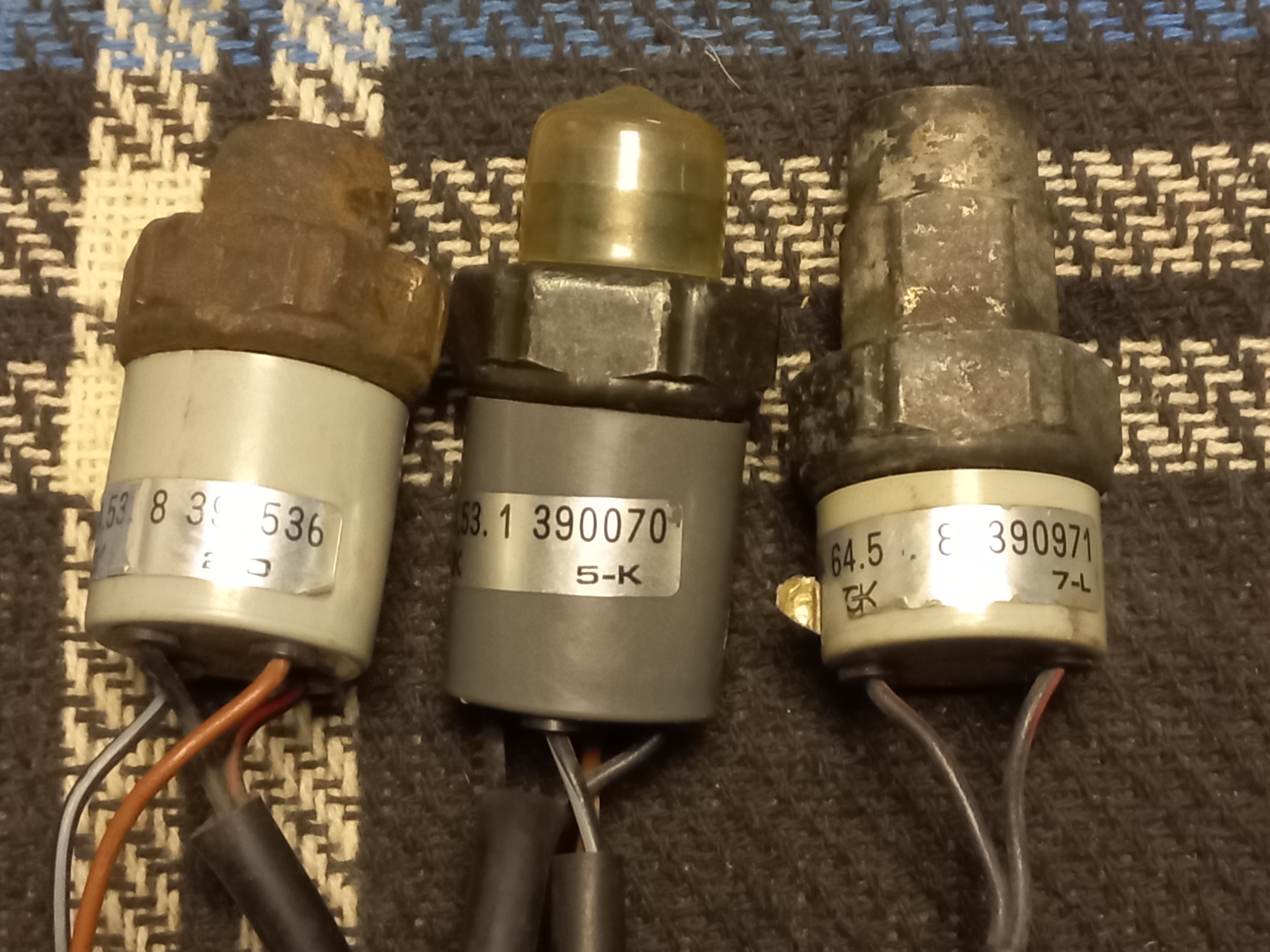
Safety air switch (64 53 1 390 070) new for E30, E32, E34 4 pins (black and white connectors)
Safety air switch (64 53 8 390 971) for E30 2 pins (black connector)
Safety air switch (64 53 8 390 536) - for E23 4 pins (black and white connectors)
On my wiring, the connector for the low pressure sensor was cut off, and the connector for the high pressure sensor was an early model, with two flat black contacts, type like this:
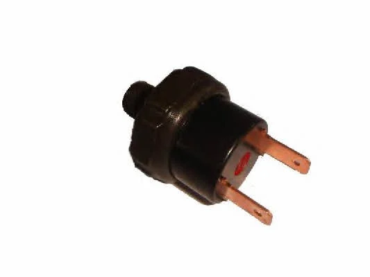
All my sensors had different connectors:

I solved this not-so-big problem with a homemade adapter. But looking at the ETM diagrams for different years of production, it became clear that there were some differences in the connection of these sensors.
On the 86 diagram, there were two separate high (black connector) and low (white connector) pressure sensors that were connected to the air conditioner wiring in series, one after the other.

The low pressure sensor opened in the event of a freon leak and a critical pressure drop. The high pressure sensor closed at a pressure of 21.2 bar, and opened when it reached 26.6 bar.
In the 87 scheme, there were two separate high (white connector) and low (black connector) pressure sensors, which were connected to the air conditioner wiring in series, one after the other. The sensors were simply swapped in the scheme, and the color of the connectors. The operating pressure ranges of the sensors remained the same as they were.

I don't really understand why they did this, but it's not critical - it practically didn't change anything, because the connection diagram remained serial. In addition, they added a serial temperature sensor on the compressor. Although, on later diagrams it is no longer there. But now we are not talking about it.
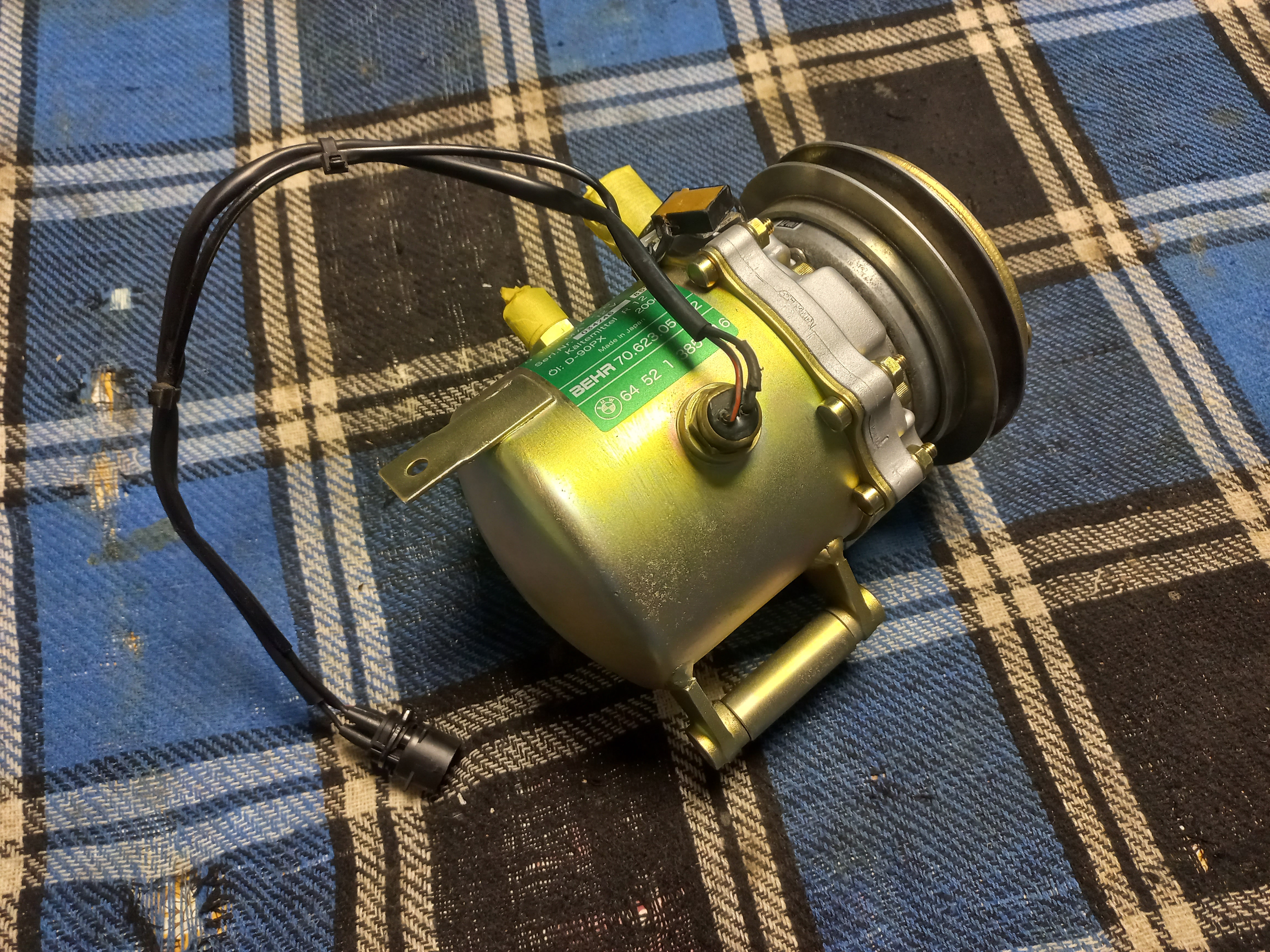
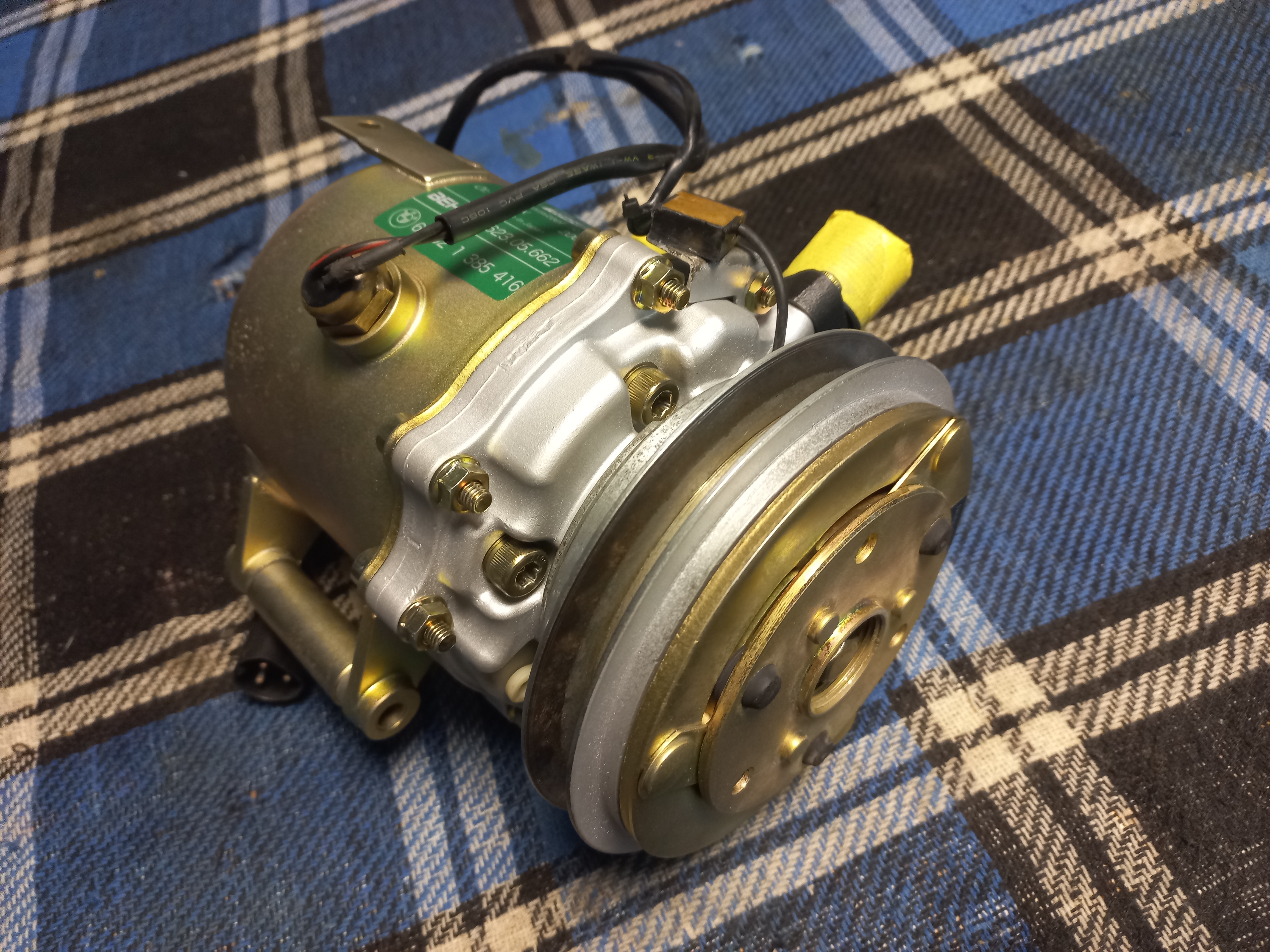
On my old dryer there was a fitting for installing two separate sensors. But on the new dryer the fitting was only for one sensor. That is, there was no place to physically install the second sensor. I had to look at an even later diagram.
On the 90 diagram there were already two high and low pressure sensors, connected serially one after the other, but physically they were located in the same housing, with one black connector. The white connector was removed from the diagram altogether. That is, it was already a double sensor - for both low and high pressure. The high pressure limit was increased to 30 bar.

In fact, nothing has changed in the circuit itself - in any case, both sensors are connected in series one after the other, and for the compressor to work, they must both be closed. Since my wiring had both black and white connectors, I decided to install a new original sensor (64 53 1 390 070) with white and black connectors. This seemed logical. Accordingly, I connected them that way - white to white, black to black. At the same time, the compressor did not start until I disconnected the white connector and installed a jumper in the wiring instead of the sensor. At first, I thought that the sensor was faulty. Although, it is new and original. But then I thought the cuts on the insulation of the white connector wires were suspicious.
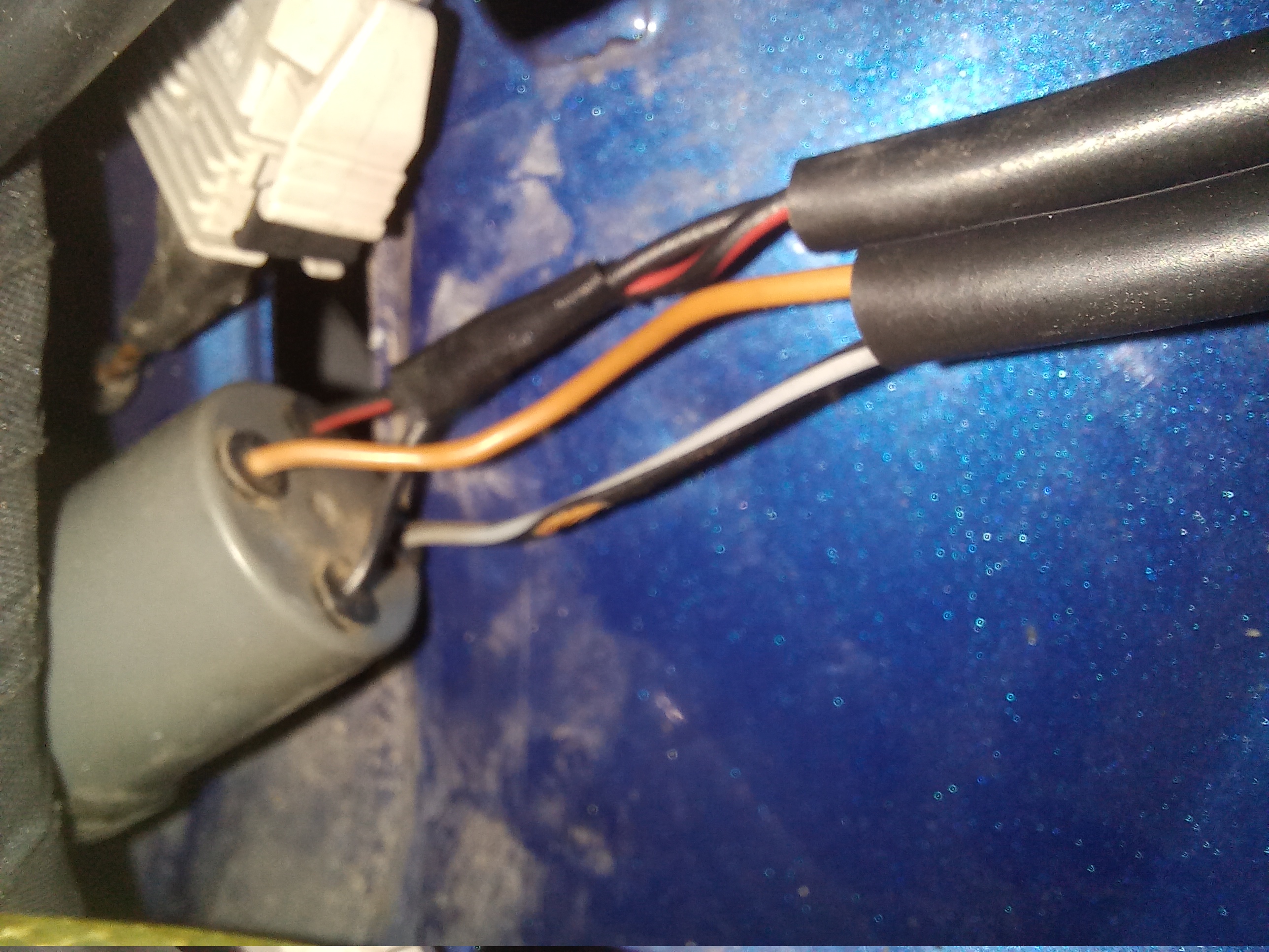
I tried to "ring" them with a multimeter, and it turned out that the white and black connectors are not connected in series! Strange. The situation became clear thanks to a friend who also installs air conditioning. He bought an analogue of the sensor, on which its parameters were marked:

HP 32 OFF - high pressure 32 bar is off
MP 17 ON - medium pressure 17 bar is on
LP 2 OFF - low pressure 2 bar is off
Judging by this, the low pressure sensor closes at a pressure of 2 bar, and the high pressure sensor opens at a pressure of 32 bar. And they both work only through the black connector. And the white connector closes at a pressure of 17 bar. This was confirmed by practical testing.
That is, these two connectors should not be in series, which is why in my case a jumper for the white connector on the wiring was needed. And the white connector of the sensor is not used in this case.
But I wonder why that white connector is used then? This sensor (64 53 1 390 070) according to ETK is suitable for E30, E32, E34.
Therefore, the answer to this question was found in the ETM 95 scheme for the E34. It shows a similar sensor (B9508), dual for low and high pressure (B8y) with a black connector (X127). The low pressure sensor opened when the pressure dropped below 1.5 bar and closed at a pressure of 2.6 bar. The high pressure sensor closed at a pressure of 21 bar and opened when it reached 30 bar.

It seems that everything is the same as in the 90 scheme for the E30. But, having scrolled through the following diagram, we find on it the same pressure sensor (B9508), but with another built-in separate sensor (B9y) with a white connector (X126).

But there is probably also an error in the diagram. In practice, this sensor closed at a pressure of 18 bar, turning on the air conditioner fan at maximum speed. After cooling, the pressure dropped to 15 bar and the sensor opens, turning off the fan. That is, this is additional system protection through a third sensor, the use of which in the E30 is not provided for by the diagram.
Now everything is clear. So, having this sensor, I decided to use its additional protective function for the E30 as well. This is not at all difficult to implement - you only need to add two short wires, of the appropriate colors, from the temperature sensor for the maximum fan speed on the radiator to the pressure sensor on the dehumidifier. This is drawn in red on the diagram.
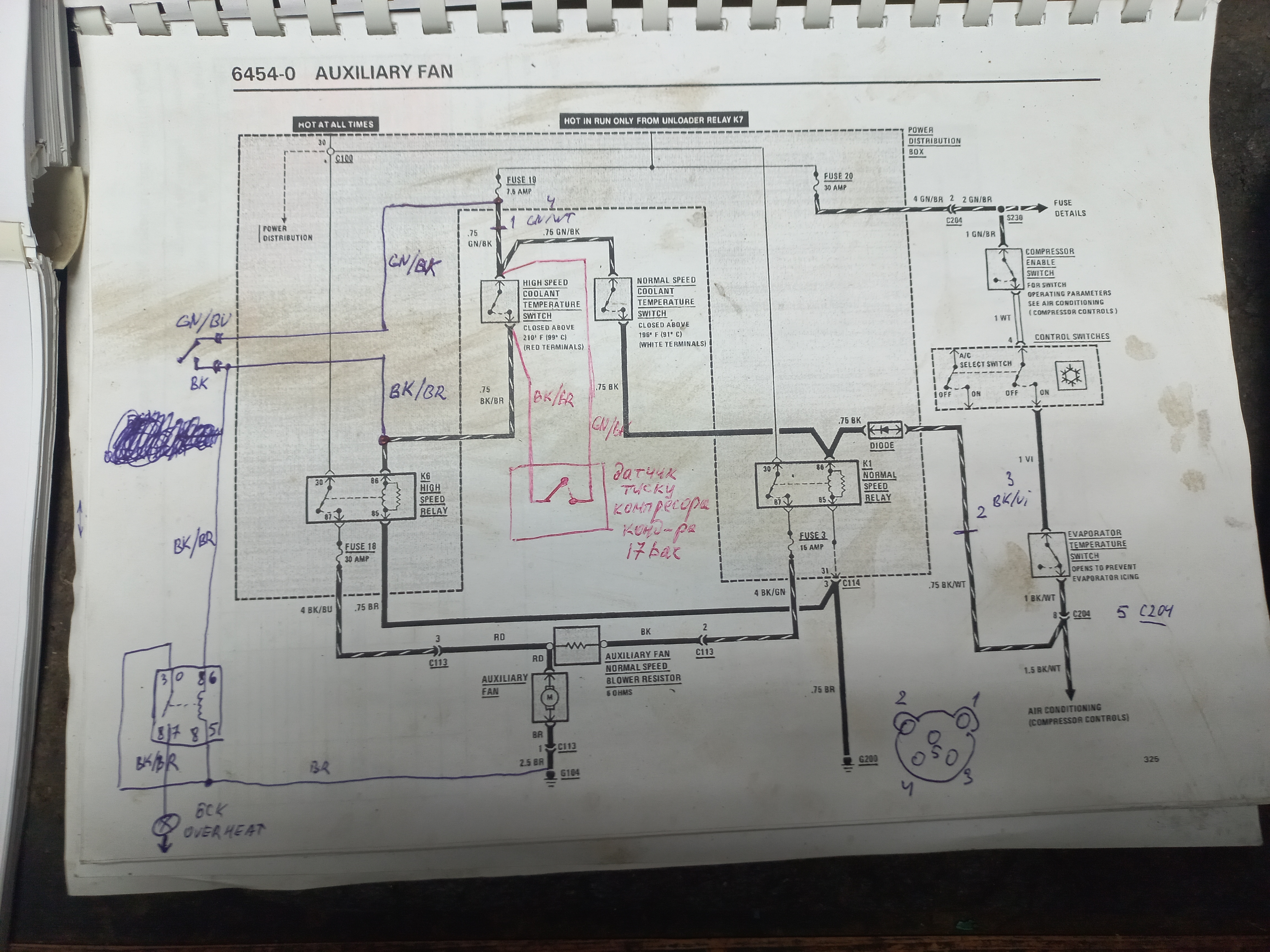
In my case, the temperature sensor is also double, but the circuit is similar.

By the way, the diagrams show in blue the connection of the button for manually turning on the maximum fan speed via the standard relay, and the additional lamp on the OVERHEAT control panel. I have already written about this before.
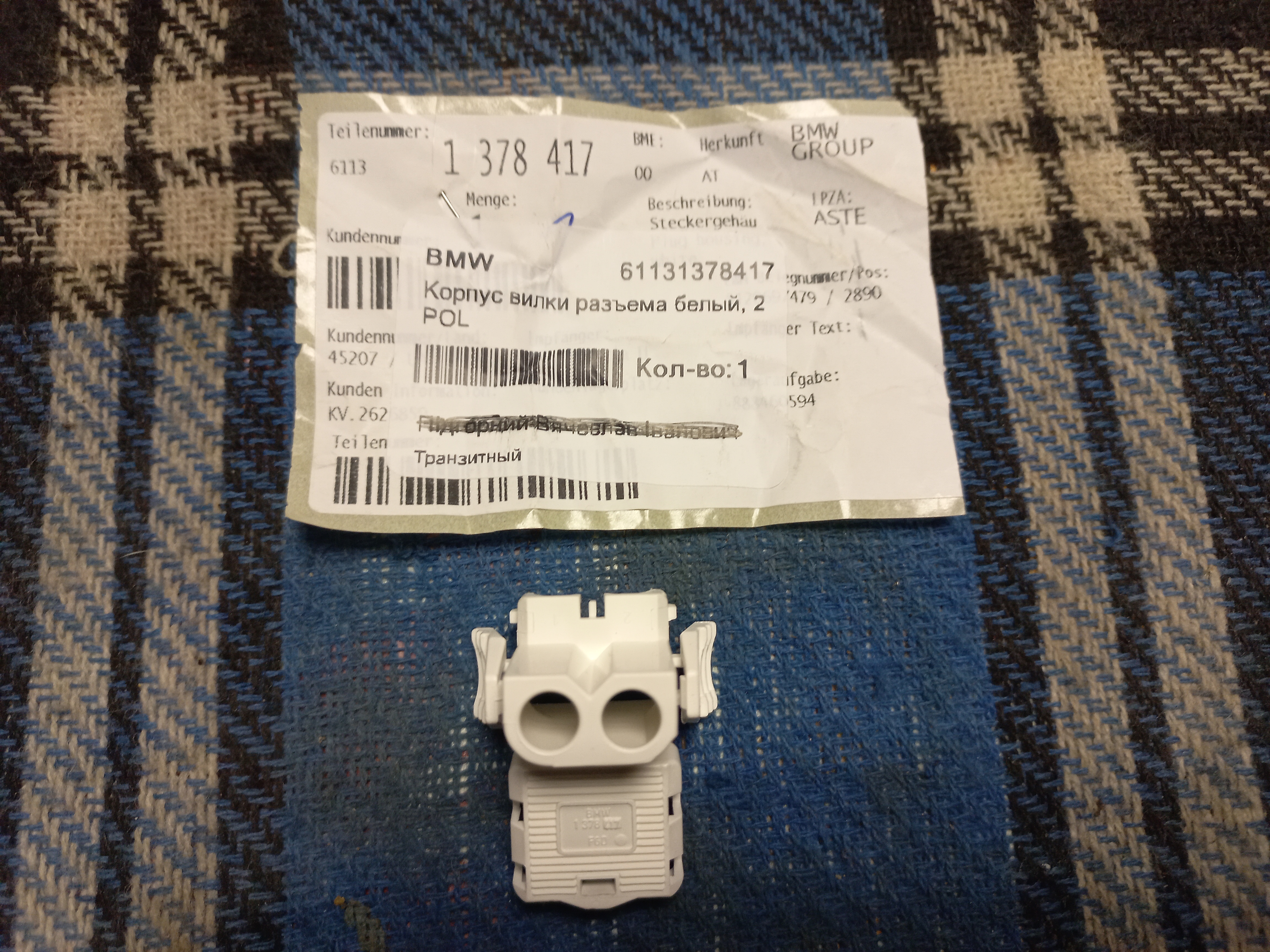
In order not to cut anything in the wiring, I decided to make another adapter - for the temperature sensor with a parallel white connector for the pressure sensor.
I also made a jumper with the yellow connectors so that they would no longer be confused with the white ones. Because somehow German engineers got a little too clever with these connectors, changing their functionality, but leaving the same colors! ) It's confusing.

So, we connect the adapter to the temperature sensor on the radiator. We connect the air conditioner wiring to its corresponding connector. And we connect the white connector of the pressure sensor to the white connector of the adapter. We connect the black connector of the pressure sensor to the air conditioner wiring, as before, through the adapter. And we install a jumper on the second connector of the air conditioner wiring (now it is yellow, instead of white).


A double, or rather triple, pressure sensor.

It's probably not for nothing that there were slots in the wire insulation - it seems that the previous electrician decided to implement the jumper in the simplest way - by twisting directly on the sensor.
But we're not looking for easy ways! )) The slots are insulated, the adapter is connected. Now it is important not to confuse the white connector of the high beam headlight ))

A third pressure sensor is connected to the adapter.

Thanks to this, if the pressure increases to 17 bar, it will immediately be automatically lowered by the fan, and not grow further, up to the critical 30 bar, and the compressor will turn off. I don’t know why this option was not used in the E30, although this sensor was used there.
A dual low and high pressure sensor is connected via a black connector with an adapter for early-type foam.

A jumper is installed on the second connector of the air conditioner wiring to close the wires in a serial circuit. A yellow connector is installed so as not to be confused with the white ones.

This completes the work with the electrical part and compressor sensors. I hope...
But that's all I managed to do. It never got to the point of replacing the hose, again, for the same reason as last time. But now on a more serious scale. After the new roof on the garage, I had to make a new roof on the house...

Therefore, there is no time, no finances, no energy for cars again... it's all over...
By the way, my E53 will now also have to spend a lot of time and finances - it also got ((

It's good that at least the E30 is in the garage, so it didn't suffer.

But, unfortunately, work on it is again postponed for an unspecified period, so there will probably be no news in the near future...

























Leave a comment: