E30 from Ukraine - "Shadow of Intelligence"

Collapse
X
 
  • Time
  • Show
Clear All
new posts
  • The_Glory
    E30 Addict
    • Jul 2022
    • 426

    #496
    Disassembly of the BOSCH BEHR R12 air conditioner compressor

    So, having "practiced" on a broken compressor, I am now disassembling my working compressor to make sure that it is clean and in good condition inside.


    Let's start with the pulley. We unscrew the central bolt on its axis.


    To keep the pulley from rotating, my old homemade "special tool" came in handy.


    The bolt unscrewed quite easily, but the clutch pressure plate cannot be removed.


    The internal thread on it confused me a bit. Although I saw a keyway, I initially thought it was screwed on with some kind of bushing on this thread. I tried to "twist" it with a screwdriver and a hammer, but of course, it was useless. I never understood why that thread was there, because, as it turned out later, it is not used at all. Perhaps on other cars something else is screwed there. But not on the E30.
    In the end, having found sensible information on American forums, I understood that the disc is simply removed from the key upwards. But no puller is suitable, because there is nothing to hook it on and push it against. The "wedge-up" method turned out to be effective. That is, I carefully hammered screwdrivers evenly around the circumference, between the pulley and the clutch pressure plate, until it broke off the axis and the key.


    The disc has been removed. You can see the cutout for the key. A cylindrical metal spacer and two washers of different thicknesses were installed in it. Obviously, these washers are needed to adjust the gap between the pulley and the clutch pressure plate.


    Now there is access to the fastening of the pulley itself.


    We clean the nut, bend the ears of the lock washer with which it is fixed.


    Using a screwdriver and a hammer, carefully unscrew the nut. Or use a special wrench, if available.


    Remove the lock washer from its groove.


    Remove the pulley, without much effort.


    If you need to replace the bearing, remove the retaining ring and press out the bearing. In my case, the bearing is in excellent condition, so I will not remove it.
    Now you can remove the electromagnetic clutch, which is fastened with six screws.


    You also need to unscrew one of the nuts holding the coupling diode.


    Then we unscrew the compressor oil temperature sensor. In fact, it does not have a through hole and direct contact with the oil. It measures the temperature of the compressor housing.


    The electromagnetic clutch with wiring and temperature sensor has been removed.


    Unscrew the two screws and remove the inlet fitting.


    Carefully remove it from the compressor housing. It is removed with little effort, since there is a rubber seal on it.


    On the lower part of the fitting there is a check valve with a spring. It is removed simply by slightly bending the four ears of the valve holder from the groove.


    It is clean inside. This gives me hope! )


    Under the electromagnetic clutch on the cover there is some part that I do not understand - a plastic holder with a felt insert.


    It simply lies on the lid in special grooves made according to its shape. Does anyone know what its purpose is? Let's take it out.


    We unscrew the eight nuts along the contour of the lid and remove the special bolts with a cut head.


    Then you need to unscrew the four bolts with an internal hexagon. At this point, the disassembly stopped a bit. These bolts are tightened with a very high torque. To unscrew them, I had to go to a friend who has a pneumatic impact wrench. There were copper washers under the bolts.


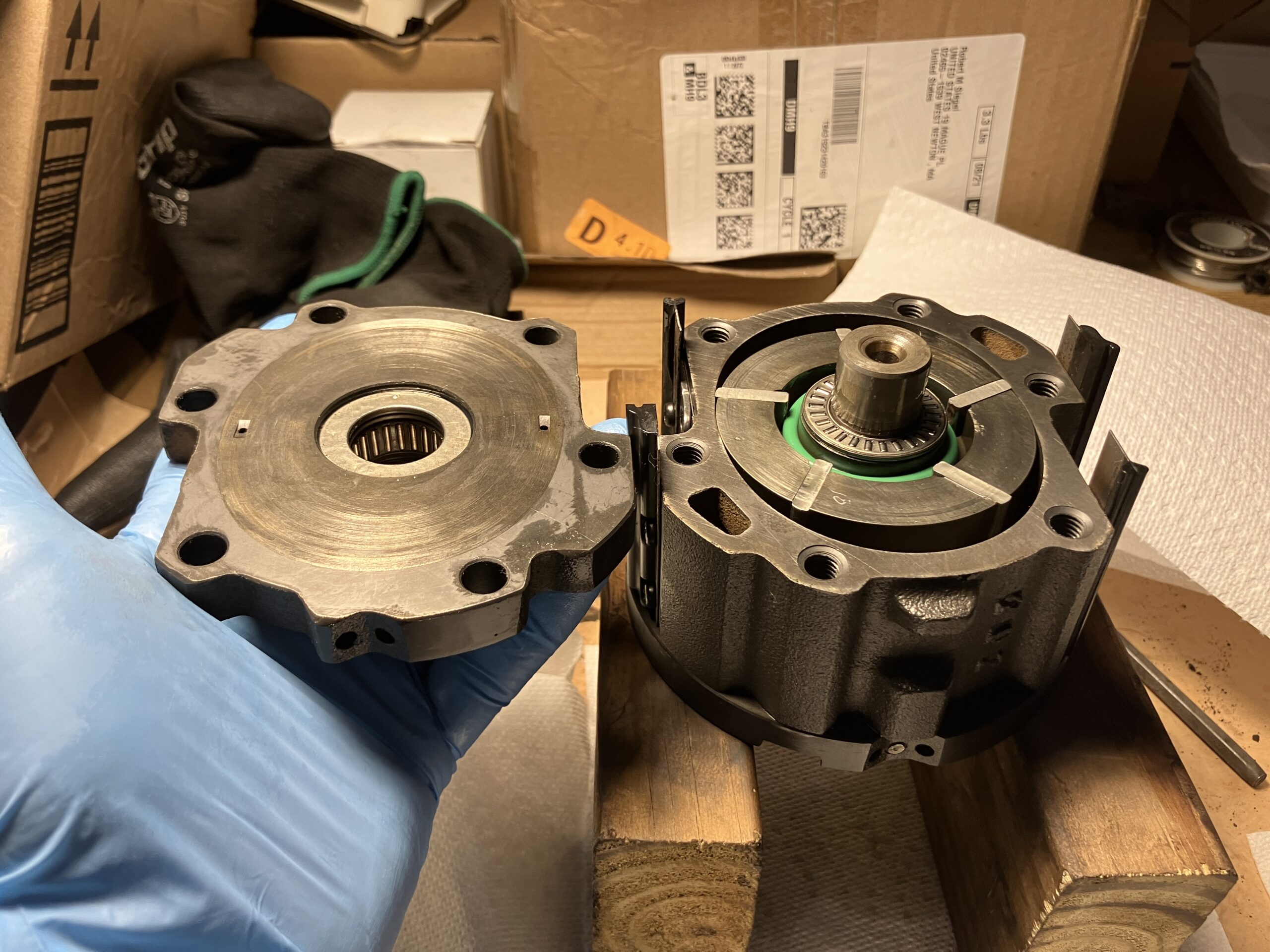
    Carefully remove the cover.


    Everything is clean and lubricated under the cover - which is pleasing.
    Pay attention to the location of the compressor in the housing - a large triangular arrow points to the outlet fitting on the housing.


    The lid is clean, but the seals will of course be replaced with new ones.


    A metal sleeve is installed in the lid.


    Which is fixed externally in the lid with a retaining ring.


    Remove the retaining ring and take out the bushing.


    A rubber seal is installed on the bushing.


    To remove the shaft seal, you need to knock out the key.


    Carefully remove the shaft seal.


    It consists of a plastic housing, and a ring made of some kind of carbon, or something similar, that is inserted into the plastic housing.


    Remove the spring and rubber seal from the inner hole of the cover.


    Two parts of the gland. A rubber seal is also installed in the plastic housing.


    The lower ring has a special recess for the spring.


    Plastic gland housing.


    Rubber seal in plastic gland housing.


    Plastic gland housing without gasket.


    The compressor sits tightly in the housing, so I took it out like this - turned it over and put it on wooden blocks and lightly tapped the housing.


    Clean grease flowed out of it.


    I took the compressor out of the housing.


    The housing inside is perfectly clean!


    I removed the sticker, because now I will definitely galvanize it.


    What can I say about the condition of the compressor - it is practically in new condition! Everything is perfectly clean, in clean oil. There is no dirt.


    I would show these photos to those "experts" who advised me to throw this compressor in the trash!

    At first I was going to disassemble it completely, but the bearings are in perfect condition, there are no backlashes, everything is clean. In addition, to unscrew the bolts of the bottom cover, you need a pneumatic impact wrench again, which I, unfortunately, do not have yet. Therefore, I will not do this.

    So, I made sure that the compressor is clean inside. I guess I could have safely installed it on the car right away, and not bother myself! But thanks to the "valuable advice of experts", now my compressor will not only work, but also be beautiful! ))
    Everything will be thoroughly washed, cleaned, painted, electroplated, blued, new stickers - everything, as always! ;)


    All bolts, housing and clutch pressure plates are sandblasted and ready for galvanizing.


    New stickers are ready.


    Everything is galvanized, I bought a new set of rubber seals, I also bought mineral oil.


    Everything is ready for assembly.

    P.S.
    The "practice" assembly of the broken compressor has already been successfully completed! ;) Could be a good compressor too....


    If it weren't for the holes in the case... )


    The electric clutch is working, the front part has been restored - it will be in reserve.​

    Comment

    • The_Glory
      E30 Addict
      • Jul 2022
      • 426

      #497
      Addendum to the previous post

      In the previous post about the disassembly of the BOSCH BEHR R12 compressor, I had two questions. Thanks to smart people, I found the answers to them. So I'll add them here.

      Question one:
      What is the purpose of the internal thread on the clutch pressure plate?


      Answer:
      The internal thread on the pressure plate is just for the puller, so as not to hammer the disc with hammers and screwdrivers.
      The puller itself is of such a plan.
      This is the principle on many cars.
      I think the principle of its operation is clear - the nut is screwed into the thread of the disk, the cone of the bolt rests against the hole on the shaft and when the internal bolt rotates, the disk is pulled off the shaft and the key. It's a clever device.

      Question two:
      What is the purpose of the plastic clip with a felt insert located between the cover and the compressor electromagnetic clutch?


      Answer:
      It's purely my assumption: a diagnostic element for checking the compressor seal. It looks like it can be removed by pulling on the ring and then inserted back. The shape is just such that it can be removed, and in what situation it can be removed, I don’t know)
      Detailed answer:
      This part is a felt oil catcher (often found in English as a compressor shaft seal felt pad or oil slinger).

      It performs several very important functions:

      Absorbing micro-oil leaks: The air conditioner compressor shaft seal (especially on classic compressors such as Denso or Seiko-Seiki) can leak microscopic doses of compressor oil during operation. This is considered normal. The felt sponge is installed just above the special drain hole of the seal and works as an absorber, absorbing these drops.

      Electromagnetic clutch protection: This is the main task of the part. If this catcher were not there, centrifugal force would scatter the oil from the shaft directly onto the friction surfaces of the electromagnetic clutch (which is mounted on top of this unit). A greased clutch would slip, overheat, and fail quickly.

      Dust boot: It also acts as an additional barrier that prevents dust, dirt, and abrasives from getting into the shaft seal from the outside, extending its service life.

      So, this is a very simple but critical element for the longevity of the compressor clutch. Before installing the clutch, make sure it is securely locked in place.
      Now everything is clear. Thanks to everyone for the answers.

      Comment

      • The_Glory
        E30 Addict
        • Jul 2022
        • 426

        #498
        Assembling the BOSCH BEHR R12 air conditioner compressor

        Everything is ready - finally, you can assemble the compressor.


        Santech rubber seal repair kit MT2107


        The seals are signed according to the markings from the catalog.


        M20-2171 internal compressor shaft seal (2pcs.)

        M95-2108 internal cover seal
        G95-3101 cover seal
        M13-2107 external cover seal
        M96-2140 gland seal
        M13-2103 cover sleeve seal
        M95-2101 inlet fitting seal

        By the way, the markings are similar to the names of Soviet car models :)

        Compressor assembly diagram and parts markings from catalog


        By the way, I found a lot of useful information here:
        It took me the full ten days from the onset of my first symptoms to test negative for COVID, but by the end of the week, I was up and around again. I figured that the basement and garage qualified as self-isolation, so I began chipping away at putting the FrankenThirty’s compressor back together. When we last saw my Behr wing cell compressor, I had fully disassembled it on the workbench to clean out the […]


        https://www.bimmerforums.com/forum/s...ressor-Rebuild

        Thanks to the authors for this.

        So, when assembling, you need to immediately lubricate everything with a thin layer of grease. I chose Errecom Mineral Oil 46 mineral oil. It took me a long time to choose, but I will write about it separately, when refueling the air conditioner.
        Since I did not completely disassemble the compressor, I do not use the two internal seals M20-2171.
        Lubricate the compressor and insert it into the housing in this position - the triangular arrow points to the fitting.


        Lubricate and install the rubber internal seal of the cover M95-2108.


        Put the spring on the shaft.


        We put on the lower ring of the gland so that its protrusion coincides with the edge of the spring.


        We lubricate and insert the gland seal M96-2140 into the plastic gland housing.


        Put the gland housing onto the shaft so that the lower ring fits into its grooves.


        Drive the key into the groove on the shaft.


        Lubricate and put the M13-2103 cover sleeve seal onto the sleeve.


        Insert the sleeve into the cover and secure it with the retaining ring.


        Lubricate and insert the cover seal G95-3101 and the outer cover seal M13-2107 into the cover.


        Carefully place the cover on the shaft. Make sure that the seals do not fall out of their seats. We tighten the four bolts with new washers from the seal repair kit.


        These bolts were tightened with a lot of torque. So that when tightening them, the compressor does not turn in the housing, we insert eight bolts along the contour of the cover, but do not tighten them completely.


        Now we tighten the four bolts with a hexagon. I don’t know exactly what torque, and I don’t have a dyno wrench. So I tightened it as hard as I could! )


        Now you can fully tighten the eight bolts along the contour of the cover.


        We lubricate and put the M95-2101 inlet fitting seal on the fitting. We fix the check valve with a spring on the fitting.


        We carefully insert the fitting into the cover and fasten it with two bolts.


        An interesting detail that I wrote about in the last post is the oil seal catcher.


        It is simply placed in the groove according to its shape.


        Located at the bottom of the cover. Leaking oil through a special groove falls on the felt insert and accumulates there. Right on the car, by pulling on the ring, it can be pulled out to check the tightness of the oil seal, or cleaned if the oil seal is leaking. Then insert it back into place. Simple and convenient.

        Screw on the oil temperature sensor and the electromagnetic clutch diode.


        We fix the wiring with a tie through the hole in the diode bracket. We stick a "12volt" sticker on the coupling.


        We fasten the electromagnetic coupling with six screws.


        The pulley bearing is in excellent condition, so I don't see any point in changing the original Japanese NSK bearing to a new Chinese one.


        We put the pulley on the shaft until it stops.


        Install the lock washer in the groove.


        Tighten the nut and secure it by bending the "eye" of the washer.


        Install the clutch pressure plate.


        To fit with the required gap between the disk and the pulley, a metal spacer and washers of different thicknesses are used. There can be several washers. In my case, there are two of them. First, we put a thicker washer, then a thin one, then a spacer.


        We put the disk on the shaft so that the groove falls on the key. The disk fits quite tightly, we even had to hammer it in a little until it stops.


        We fasten the clutch pressure plate with a bolt and washer, holding it with a homemade wrench or something similar.


        Next time, if necessary, I will use its internal thread for a special puller to remove the plate - now I know! ;)

        We stick a sticker indicating the direction of rotation.


        The compressor is assembled. It is advisable to immediately pour 100 milliliters of oil into it through the inlet fitting. The total volume is 200. The rest of the oil will be poured when refueling the air conditioner.


        The final "touch" is a new sticker, which indicates the BOSCH, BEHR, BMW numbers and the serial number. It also indicates the type of freon R12, the type of oil D-90PX and its volume 200cm3. Made in Japan.


        I have another question - why do you need a metal strip with a hole on the back of the case? It is definitely not for mounting the compressor. It looks like a terminal for the "mass" of the housing. But I haven't seen this in either ETK or ETM... Not used?

        The compressor is ready for installation.


        Beautiful! )

        P.S.
        Maybe I'm writing too much, but I've been looking for something like this for a long time, so let it be! ;) Maybe it will be useful to someone.

        Comment

        • The_Glory
          E30 Addict
          • Jul 2022
          • 426

          #499
          Adapters for jacks

          After a little fiddling, I finally pushed the compressor into place, from above through the hood, and even screwed it to the engine. But to put on the belt, tighten it and fix it, you need access from below. In addition, to put on the air conditioner compressor belt, you first need to remove the power steering belt. And to do this, you will probably have to remove the lower protective plastic shield. Since, unfortunately, I do not have a lift or a viewing hole, I will probably have to make a "mini-overpass" on the garage ramp again. Or try to simply raise the front part on both sides with two jacks.
          I'll start with the simpler option - jacks.
          I have been meaning to make some adapters for jacks for a very long time, so as not to scratch or bend the lower edge on the sills with them. Finally, this day has come! )
          I found suitable pieces of iron in the garage, cut them, cleaned them.


          And made such adapters for both of my jacks.


          Two adapters in standard places, under the thresholds.
          For one jack, we used its standard insert and welded a round steel washer and two supports from a 20x20mm square to it.
          For another jack, a ring made of a pipe with a diameter of 50 mm, a height of 15 mm was welded to the steel washer from below.
          I glued soft pads to the supports.
          Two adapters for the silent block of the rear beam - rings made of a pipe with a diameter of 50 mm, a height of 40 mm. I put a rubber hose cut lengthwise on the end of the pipe.

          Adapters in standard places, under the thresholds.


          The adapter fits well in its standard place on the threshold, without touching its lower edge, and the BBS plastic pads.


          Adapters for the silent block of the rear beam.


          The adapter fits well under traction, without touching the nut and bolt of the beam.


          I hope that now lifting the car will be easier and safer.


          I also glued soft pads to the standard jack spacer so that, if necessary, it can be lifted under the side members or some other surface.


          Now I can try to screw the compressor.

          Comment

          • The_Glory
            E30 Addict
            • Jul 2022
            • 426

            #500
            Assembly_201. ETK_64_Heating and Air Conditioning. (Part 12) Electromagnetic Clutch and Air Conditioning Compressor

            Finally, it came to installing the air conditioning compressor on the car - the last part of the ETK on assembling and installing the air conditioning in a BMW E30.

            Electromagnetic clutch


            Part No. 1 - Bosch/Behr electromagnetic clutch (64 52 1 386 297). Complete with bolt and mounting washer.
            Part No. 2 - Bosch/Behr sealing profile (64 52 1 381 193). If I'm not mistaken, judging by the photo on the Internet, this is a plastic compressor shaft seal with a seal. I don't understand why it is shown in this section in the ETK, but I wrote about it in detail in the compressor assembly section.
            Part No. 5 - Bosch/Behr thermal switch (64 52 1 385 417). Compressor oil temperature sensor with wiring.

            Parts No. 3, No. 4, No. 6, No. 7 are not used.

            Air conditioner compressor


            Part #1 - air conditioner compressor (64 52 8 385 713). Freon R12.
            Different compressors were used for the BMW E30 air conditioner - Bosch/Behr, Seiko/FER, DENSO/Hischier. There are many types of them in the ETK with different numbers. But the main difference is the type of freon. For early versions, R12 freon was used, and for later ones, the more environmentally friendly R134a freon. There are original conversion kits (82 31 9 067 394) from R12 to R134a. But I decided to try to leave the air conditioner on the old R12 freon. Although, this creates some problems with its refueling, due to the fact that it is already very difficult to find in stock. But we are not looking for easy ways! )) Especially since this freon cools much better. So I will try R12 first. If nothing works, then I will have to switch to R134a.

            So, the Bosch/Behr compressor is restored and ready for installation.


            AVX13x825 V-belt - I have already written about it in the relevant section.


            ERRECOM Mineral Oil 46 Lubricant


            I will write about the lubricant in more detail. For the old R12 freon, only MINERAL lubricant is used. For R134a freon, synthetic lubricant is used. After talking to our modern "experts", I got the impression that they are not concerned with this issue, and usually pour whatever lubricant they have on hand, regardless of the type of freon or the type of compressor. As a rule, it is something like PAO 68. When I asked about the viscosity of compressor oil, some "experts" were surprised and didn't even know that it can be different, just like for motor oil! )) Unfortunately, now there are only "tick-tock experts" around... So far I haven't been able to find a sensible specialist in car air conditioners who has a specialized education and understands how it works - there are only "refuelers" around who can only fill with whatever they can find. So I had to figure it out myself.
            I don't claim to be the truth - all the information is from the Internet.
            I found these tables on the use of lubricants for different compressors. Maybe it will also be useful to someone.


            According to this table, the Bosch/Behr compressor uses D-90PX grease. This is also indicated on the sticker on the compressor. But I couldn't find such grease anywhere. The table shows PAG100 grease as an equivalent, but this is a synthetic grease that is used when converting to R134a freon. That is, in my case it is not suitable for R12 freon.

            I found another table by car brand.


            According to this table, for BMW E30 with R134a freon, PAO 68 synthetic grease is used, or according to the original ETK number (81 22 9 407 724), PAG 46 synthetic grease. That is, in both cases it is a synthetic grease, but of different viscosity.
            In the same table for the BMW M3 E30 with a piston compressor and R12 freon, Suniso 5GS mineral oil is used. The viscosity of this oil is 100.
            So, we already have four options for different lubricants, different viscosities... Probably, you shouldn't trust these tables too much...

            So I thought and decided that it would be logical to take only MINERAL lubricant for R12 freon, but of the viscosity that BMW recommends according to the ETK - that is, 46.

            It seems to me that this will be correct. After all, the type of lubricant depends only on compatibility with this freon, and the viscosity, regardless of the type of freon, must correspond to the type of compressor for its normal lubrication and operation. If I'm wrong, correct me. While it's not too late ))

            So, we install the compressor. I installed its mount and tension bracket when assembling the engine. It would have been more convenient to do it from below, but due to the lack of a lift or inspection pit, I tried from above... ) After several attempts, I still pushed the compressor in and even screwed in the upper mounting bolt.


            But there is no access to the tension bolt from above. Not to mention the belt. After all, in order to put the air conditioner compressor belt on the crankshaft pulley, you first need to remove the power steering belt from it. So, I had to raise the front part again on jacks and climb under the car. I really didn’t want to remove the lower plastic protective shield and brake air ducts. Therefore, it was very inconvenient. But I still screwed the compressor on.


            It was also not easy to push the belt between the pulley and the viscous coupling impeller.


            But it was possible - the belt is in place and tight.


            Now all three pulleys are involved - generator, air conditioning compressor, power steering.


            The compressor is installed.


            But the most difficult thing was to tighten the power steering belt and screw in its pump through these ventilation holes in the lower protective shield... I struggled with this for a long time, but in the end, I screwed in the pump.


            We connect the compressor wiring. I have a new dual low and high pressure sensor installed on the dryer. The low pressure sensor has a black connector, and the high pressure sensor has a white one.


            My wiring was missing the connector for the high pressure sensor, so I had to restore it. Housing (61 13 1 378 417).


            The connector for the low pressure sensor was for the old-style sensor - with two separate flat contacts and a rubber cap for the sensor.


            So in order not to cut the wiring, I had to make another adapter for the new sensor.


            Connect the adapter to the air conditioner wiring, and then connect the low pressure sensor to the adapter.


            Connect the restored white connector to the high pressure sensor.


            I previously wrote that my old compressor did not have an oil temperature sensor, so it does not have wiring for it. In fact, this is just a factory jumper that includes this sensor in series with the electromagnetic clutch wiring. The new compressor has this sensor. Therefore, we take the standard jumper and rearrange it in the empty places on the 3-pin connector of the air conditioner wiring.


            We connect the compressor.


            Earlier I asked why there was a metal plate with a hole on the compressor. One of the answer options was - a hole for the clip fixing the compressor wiring. I liked this option. I don't know if it was like that at the factory, but I installed a wiring holder there and fixed the compressor wiring with it.


            By the way, while I was pulling the wiring there, I noticed that water started to drip a little from the seal of the washer tank pump. I bought all three new seals, I will change them later just in case.


            I hid all the connectors under the washer tank, fixed the wiring with a tie to the other harnesses.
            All that remained was to screw on the two hoses.


            Pre-filled the compressor with 100ml of oil.


            The total oil volume is 200ml, but the rest will be filled in when filling the system.


            And then I had a bad luck... As was the case with the ABS unit fitting, the outlet hose fitting does not want to be screwed into the thread.... I still don't know what to do with it...


            And that's not all... The inlet hose fitting has a special bend for the compressor flange, which is installed at an angle. On my compressor, the flange is installed vertically, so the hose does not reach it...


            That's such a mess... But I will solve this problem - I will rearrange the flange from my old broken compressor. It has the right shape. It's not for nothing that I restored it too, although its condition is a little worse... But what to do with the damaged thread, I haven't figured out yet...
            And the "finish" was so close..... )))

            P.S.
            If anyone in Kyiv has contacts of a smart R12 air conditioner repairman, I would be grateful if you could share them. But, specifically a repairman, not a "refueler" :)

            Comment

            • The_Glory
              E30 Addict
              • Jul 2022
              • 426

              #501
              Assembly_201. ETK_64_Heating and air conditioning. (Part 12) Electromagnetic clutch and air conditioner compressor (continued)

              So, last time I stopped at the fact that the outlet hose fitting did not screw onto the compressor flange, and the inlet hose fitting did not reach the compressor flange at all.
              I started with the simplest - I unscrewed the inlet flange from my compressor and from another, broken compressor. The difference is obvious.


              Let me remind you that my "new" compressor was removed from a BMW E34 with an M20B25 engine. And the broken "old" compressor was removed from a BMW E30 with an M20B25 engine. The difference is in the shape of the inlet flange - for the E34 it is straight, and for the E30 it has a slope and an additional valve. Of course, I noticed this immediately, but I thought that the hose could be turned and screwed. But it turned out that its length was not enough for this. Therefore, I will simply replace this flange. I noticed rust residues on the inner mesh, so I cleaned the flange again with a solution of citric acid, rinsed it thoroughly, blew it with air and re-coated it with a cold blueing agent. Now the flange and its inner mesh are perfectly clean.


              Complete with a gasket, valve and valve, - ready for installation.


              It was more difficult with the outlet hose fitting. Either something got under the thread, or something went wrong, or I'm clumsy... )) But the fitting didn't want to screw onto the compressor flange at all, and the first thread turn was even slightly damaged...


              I already thought that I had ruined either the hose or the compressor. But thanks to my brother, I managed to fix everything - he understands these threads and flanges much better than I do. The thread on the compressor flange was "driven" with a similar nut from the fitting of an old air compressor. And to "drive out" the thread on the hose fitting, we had to take a broken compressor as a "donor" - we cut off that flange from it and carefully repaired the thread on the fitting with it.


              Here is such a "repair special tool" )


              And after that, finally, the outlet hose fitting was in place. Accordingly, the necessary inlet hose flange was installed.


              Now the inlet hose is normally in place. Very carefully screw the inlet hose flange to the fitting.


              And this is a victory! )) Both hoses are screwed to the compressor.


              It seems a bit strange and illogical to me that the inlet hose has thermal insulation, and the outlet hose runs even closer to the exhaust manifold, and does not have thermal insulation.


              I checked the photo from ETK - that's how it should be. I even had the idea to install it there additionally.... Does this make sense?


              Finally, the air conditioner kit is completely installed!


              Now all that remains is to fill it and hope that it will be airtight and will cool well! )

              P.S.
              By the way, yesterday I drove around my village a little - it's very hot in the car at +36! )
              I just stopped by an elderly air conditioner repairman - it's clear that the man has been working in this field for a long time and has the appropriate knowledge, and not just a "refueler" ;) He advised me to contact his colleague, who will easily fill the air conditioner with R12 freon. In addition, he is also nearby, almost near my house. We made a preliminary agreement with him, so I will go and try to fill the air conditioner soon.

              Comment

              Working...