
I just gave the thread a read. Excellent mix of fabrication and electronics! I've subbed for updates.
Metal work like your turbo inlet tube made to clear the rad hose is ace.
I also love that touch-screen OBC replacement. May have to explore a similar option for my E30 running MS3X (once everything else is done).
-
Schematic is “done” for the touchscreen OBC. Contemplating exactly how I want to lay out the PCB. TE Connectivity makes some pretty nice looking enclosures for PCB-mounting bulkhead DTM connectors. I want to do it with dual 12-pin connectors but it is really difficult to source all the parts right now.
Another small job knocked out. Rewired the intercooler heat exchanger fan to run with intercooler pump instead of engine radiator fan. Noticed the intercooler fan had a bad connection, tried to repair it but the motor housing is stamped/spot welded. For $25 I just got a new one, all back together now.
At some point in the not-so-distant future I might upsize the intercooler radiator. I’ve got about 90sq-in of core area, could easily fit a 12”x12” core, might be able to fit a 24”x7” although it could get a little tricky with fittings. 24”x12” also might just barely be doable. It really will only make a difference in heat soak, would need a bigger water-air core for better short-term performance. Going to delete the ABS unit soon, which will clear up a lot more space for a bigger core in the future. Last time I checked, it performs pretty decently for being a cheap, smallest-offered kit. After several pulls on warm days, MAT will get up to ~50F+ambient. Going through a couple gears hardly does anything. Will do more up-to-date testing before I swap any of it out.
Frozenboost.com has their warehouse in town, which is highly convenient, and they have a nice 50% off shelf for items with minor defects.
 Untitled by Mikey Antonakakis, on Flickr
Last edited by mikey.antonakakis; 05-23-2022, 05:31 PM.
Untitled by Mikey Antonakakis, on Flickr
Last edited by mikey.antonakakis; 05-23-2022, 05:31 PM.Leave a comment:
-
In other project updates, working on a PCB for the dash display/VGT controller/CAN interface/Boost controller, schematic is 20-30% complete here:
 Capture by Mikey Antonakakis, on Flickr
Last edited by mikey.antonakakis; 05-23-2022, 05:29 PM.
Capture by Mikey Antonakakis, on Flickr
Last edited by mikey.antonakakis; 05-23-2022, 05:29 PM.Leave a comment:
-
All that said, I did get a bit of perspective. I’m on a ancient 2.7L with low compression ratio and the “wrong” pistons (fully eta bottom end with 885 head), and a fairly big cam (Z45 turbo, 280/280). My turbo is 60mm in, 60mm out. The new 911 turbo has VGT, a very modern 3.8L, and a 55mm in/61mm out turbo. So, similar on turbine side at least. Makes peak torque from 2500-4000rpm, 640hp at like 6700rpm.
With that in mind, and my still far-from-ideal VGT algorithm/tuning, I am I think doing “not bad” considering that albeit slowly I can make significant boost above 2500rpm, and above 4000rpm I can make lots of boost pretty quickly. Flatshifting and VGT make things really good already from gear-to-gear, even when I am a little slow with the shifts and not truly staying WOT during the shifts:
 boost_flatshift_2022-05-19 by Mikey Antonakakis, on Flickr
Notes: rolled on in second gear, running wastegate spring pressure only (160-165kPa). Short-shifted 2-3 at 6300rpm, short-shifted 3-4 at 5000rpm. Lifted to 75% on the 2-3 shift, dropping boost target (worse VGT response). Stayed WOT for 3-4 shift. Shift times (based on spark cut/retard) were about 0.5s. Maintained MAP at 135kPa on the 3-4 shift. Turbo speed dropped from 78k to 64k on the 3-4 shift. VGT opened too early after 3-4 shift, I think.Last edited by mikey.antonakakis; 05-22-2022, 08:10 AM.Leave a comment:
-
Got over a foot of snow yesterday so testing is on pause. Been spending this time doing some thinking on the VGT control algorithm. As-is it works pretty well using only
MAP, boost target, and engine speed as inputs, with only a couple hours of street tuning. As varg and others have pointed out though, it would in theory work better to consider turbine power, which is heavily dependent on mass flow - close vanes too much and you choke the flow, making it counterproductive, and trying to maximize turbine power when I need more
boost would give the best transient response. It’s a little difficult to practically measure and model the relevant parameters, though.
So far I have essentially been iterating my way backwards into this faking this type of control, but it is pretty tough to really get it dialed in with street tuning where I live (there are almost no level or constant-grade stretches of road). My current control method is to have rpm-dependent “most-closed” vane position. I then have a kind of dead band in boost error (target minus actual) before I start opening the vanes, and open them linearly after that (currently 35% I think). For example, if I go to WOT and my boost error is 100kPa, I close the vanes to the allowable minimum, then once my boost has reached 35kPa I allow the vanes to open linearly with the remaining boost error, so vanes reach fully open once I reach my boost target. By tuning this simple parameter of allowable most-closed position I am trying to maximize turbine power iteratively, at least at the start of spooling up. I think my use of a deadband might be backwards though. I probably need to make the vanes immediately start opening as boost rises, and still be partially open once I reach target boost since at lower rpm there’s probably no meaningful difference between say 50% and 100% open.
Better (at least quicker to tune) would be measuring exhaust manifold pressure and temperature and maybe switching to a target turbine expansion ratio (using temperature correction). Since I measure turbine speed I could possibly incorporate it as well, and I think Megasquirt 2 in speed density mode can broadcast calculated mass flow (or at least I can calculate it based on other parameters), maybe I could even get a decent estimate of turbine power. If so, I could pretty quickly tip-in to WOT at various engine speeds to map out how turbine power responds to vane position. Any of this requires me to add exhaust temperature and pressure sensors, though.
In the short term, I can probably get the tuning dialed in better with this method:
-Run with fixed wide-open vanes at a variety of engine speeds, focusing especially on the initial tip-in to WOT to get fuel map tuned decently (should already be pretty close). This gives a baseline AFR.
-Re-enable vanes to close and at a variety of engine speeds, go to WOT and repeat with a variety of allowable most-closed settings at each engine speed. See how AFR and inital turbo shaft acceleration responds to changing most-closed setting. Too much richening indicates loss of mass flow, but shaft acceleration would probably tell the story the best. This should build a very decent map of most-closed position vs. engine speed.
-Once most-closed map is built, focus on mapping the vane ramp rate vs boost with similar method. Difficult to do this repeatably in practice, though. But similar idea, trying to find the edge of noticeable richening of AFR is probably a good starting point, and monitoring shaft acceleration probably tells the best story. Either way I probably need to fix my algorithm to reverse the dead band in vane response, so the vanes start to open a bit as soon as boost starts to rise.
With all of that method though, there’s still a big variable: EGT. This setup is very sensitive, it spools so much harder when the exhaust is good and hot. I really need to get EGT sensor in there.Leave a comment:
-
Definitely thought about it. Supply pressure is a little more stable now and PID is getting really close to dialed in. Was messing around with it just now and realized my solenoid open/close thresholds were a bit off (I had changed PID frequency and regulator pressure since my last check and it made a significant difference). Once I recalibrated those thresholds things improved immensely.Originally posted by tyeler18 View PostLeave a comment:
-
Have you thought about CO2 over compressed air? That would give you a more stable control and not have to worry about your tank fluctuating in pressure as often. A 2lb bottle on this thing would probably last a year or more.Leave a comment:
-
Got rid of the manual boost controller and went for a spin this evening to see what boost it’s making on wastegate spring only. ~165kPa absolute, or about 9.5psi “boost”. Note that this would be 9.5psi boost above atmospheric at sea level, about a 1.65 pressure ratio. Because I live ~6000ft above sea level, this is actually a 2.06 pressure ratio (barometric pressure here is about 80kPa vs 100kPa at sea level). So more like 12.5psi boost above atmospheric pressure. But would make roughly the same power as 9.5psi boost at sea level (165kPa MAP).
I’ve got code written to fully integrate the dome pressure PID control into my VGT control (and maybe add a little more flair to the touchscreen OBC), but the PID constants need a little more tuning before I run it. I had it pretty solid at one point but didn’t write down the values, oops. Part of the trickiness is that variation in compressed air supply pressure makes a big difference in the PID tuning, and with a 1-gallon tank and crappy regulator the pressure can fluctuate and drift pretty significantly. I might get into more detail on this later on, but there’s also fluctuation in pressure due to the relatively slow PWM frequency that the solenoids run on. I fixed this with a software low-pass filter, but any filter (analog or digital) will usually introduce a time lag, which can also throw off the stability of the PID loop, so the filter also needs to be reasonably tuned.
To oversimplify a bit, once the dome pressure PID control is tuned, I need to target a dome pressure that gets me to my desired boost, and to do that I need to know the baseline wastegate spring-only boost, hence tonight’s test. Any added dome pressure more-or-less adds to the baseline boost. So if I target 180kPa MAP, and I have 165kPa on wastegate only, I need 15kPa in the wastegate dome to get there.Leave a comment:
-
Which Arduino board do you have?Originally posted by e30davie View PostLeave a comment:
-
oh. much appreciated for the link. and i will definately take you up on the offer if i get stuck
Do you have any recomendation for a CAN reciver module?
Leave a comment:
-
I have something that might help you with that:Originally posted by e30davie View Post
I wrote an Arduino library to handle the Megasquirt CAN protocol. You'd still need to run a normal CAN library to handle the actual communications, and when you receive a CAN message this library will process the message (Megasquirt uses a unique protocol) and give you access to all the values. I'd be happy to help implement it, the github repository is a little sparse on "getting started" examples right now.Leave a comment:
-
some really cool stuff in here, nice work. the CAN bus stuff is awesome.
I have an arduino and little OLED screen that i have been meaning to do something similar with my mega, just data display would be my goal for the time being. You might have enthused me to spend some more time on that..Leave a comment:
-
Freshly-printed OBC touchscreen housing. Originally I printed it from PLA, but that doesn’t have great heat resistance and got a little saggy over time. This one is PETG, which should handle the heat a little better.
 Dash display by Mikey Antonakakis, on Flickr
 E30 touchscreen OBC by Mikey Antonakakis, on Flickr
Forgot to snap a pic of the 12-pin bulkhead connector, but here’s the old housing as it came out of the car the other day. Total of 17 wires coming into/out of the housing, as well as a USB cable to handle reflashing microcontroller and display firmware:
 E30 Touchscreen OBC bulkhead connector by Mikey Antonakakis, on Flickr
Currently, the following stuff lives in this housing:
-powered by ignition-switched 12V
-switching regulator inside to run the system on 5V
-3.3V power provided for analog sensors
-contains CANBUS interface
-pulls data from Megasquirt via CAN (it can access I think over 200 parameters from Megasquirt)
-reads data from analog oil pressure sensor
-reads data from analog fuel pressure sensor
-reads data from analog wastegate dome pressure sensor
-contains VR signal conditioner to read turbo shaft speed
-takes various parameters via Megasquirt CAN to feed into VGT control algorithm
-sends VGT commands to turbo via CAN
-reads data from turbo (received VGT position command, actual VGT position, VGT control loop data, VGT actuator temperature)
-sends data collected from pressure sensors and turbo back to Megasquirt via CAN
-controls wastegate solenoids, now with PID dome pressure control algorithm (almost fully integrated now)
-runs touchscreen OBC
-creates and conditions signal for econometer to function with Megasquirt and 700cc injectors
Touchscreen OBC includes recreation of the stock OBC with functional buttons to access various gauges, such as:
-boost
-oil pressure
-fuel pressure
-AFR
-stock-style analog clock
-combo turbo data gauge (boost, VGT position, turbo speed)
-maybe more to come soonLast edited by mikey.antonakakis; 05-17-2022, 06:43 PM.Leave a comment:
-
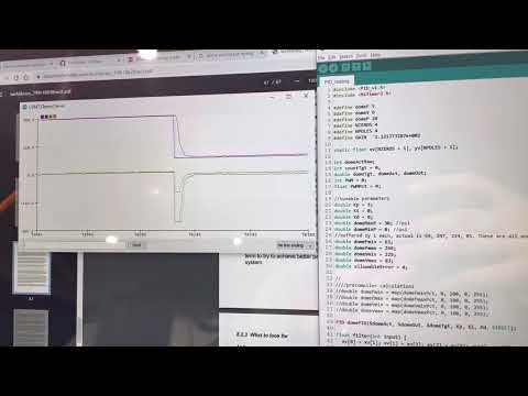
DIY dome control PID controller is functional! Needs a little more tuning and testing before I fully integrate it into the VGT/dash display code.
This quick video is testing/tuning code that only does wastegate dome control. Top pair of lines are dome pressure target vs actual, bottom is the control signal (viewed in two slightly different scales to validate the code is working as I expected). This is running on the in-dash hardware with the compressor, wastegate, solenoids all installed in the car - the nice thing is I can bench tune it without the engine running, let alone needing to drive the car.
 Last edited by mikey.antonakakis; 05-16-2022, 05:24 PM.
Leave a comment:
-
Started wiring up a pressure sensor for wastegate dome pressure control to replace my manual boost controller. Needed to remove my custom OBC/dash display and open it up to run a few more wires for the pressure sensor, route those through the firewall, and wire up the connector for it. Need to update the dual solenoid plumbing slightly as well. Mostly done with all that, should finish up later tonight.
This will be a nice upgrade, mainly because it will make the combination of boost control and VGT control more elegant. Currently I use the Megasquirt boost target map to feed boost target into my VGT algorithm - need more boost? Close the VGT. Need less? Open it. Hit boost target? Open VGT fully. It's more complex than that, but that's the basic idea. The current shortcoming is that I need to tune my boost target map in Megasquirt to match the manual boost controller setting. In other words, the MS boost map is driven by the manual boost controller. This makes it a pain to tune and leaves it open to variability.
With the planned dome pressure control, I'll instead use the MS boost map to drive the actual boost level. I'm already set up with compressed air and dual solenoids, so the last piece is to add a pressure sensor to monitor dome pressure, and remove the manual boost controller altogether. With wastegate dome pressure being measured and controlled by the dual solenoids, I can implement a PID control loop to directly control wastegate dome pressure. For those not familiar, this is a super effective way to control boost. Rather than trying to control actual boost level (very difficult because the whole engine system influences boost level), you just control the the pressure in the top chamber of the wastegate. With zero pressure in the wastegate dome, you are simply running on wastegate spring pressure. Any pressure added to the dome adds to your boost level, in a nearly linear relationship. If wastegate spring pressure is, say, 8psi, set wastegate dome pressure to 10psi and now you're making 18psi of boost (again, more or less). It's much easier to control pressure in a nearly fixed-volume pressure chamber than the entire turbo engine.
The other benefit is one that I've already implemented in the car - you can modify the PID loop to do things like send full compressed air pressure to the wastegate dome to make sure it stays fully closed while the turbo is spooling, super important for my VGT setup since closing the VGT can cause enough exhaust manifold pressure to unseat the wastegate and kill the spool (especially true if you're using a weak wastegate spring).Leave a comment:

Leave a comment: