
Couldn't wait to get home. Some very useful info in this thread. Good work!
-
 clutchCTRL!Move with a purpose.- 1991 325iX 4dr/5spd- 1976 2002 SlickTop/2.7i M20/G260- 2000 323i AT2016 Mazda CX3 Sport AWD
 -
-
Some updates for everyone....
Yesterday I got two runner extensions tacked onto the manifold. As you can see I've done a bit of work to the manifold hogging out material. That's so the end of the runner matches the ID of the extension.

I'll be going back once things have been fully welded to blend any remaining ridges...

If you have a keen eye you'll also notice that I knife edged the extensions. That's so that inside the silicone coupler there won't be a step for the air to run into...

Tacking on those two extensions allowed me to do this :)


First thing I noticed was that the dip stick tube was barely clearing the throttle bodies and would probably be an issue once the v-stacks were put on...

Yeah, that's not going to work....

Solution: Use the box end of a big wrench to make a number of small bends at a few points along the dip stick tube...

End result: I should be able to make it clear in the car...

Then I started thinking about joining the two sets of throttle bodies so that they can be operated by a single cable. I popped off the end cap as well as the TPS....

My initial thought was to replace the nut on the one side with a threaded stand off. Then machine a part that I can thread into the stand off that has a slot on the end that which will mate up with the tab that actuated the TPS. That way I'd be able to adjust the coupler then lock it down with a jam nut.
My concern was that the shaft is made out of brass and that tab is pretty thin. That tab was only ever meant to actuate a TPS, not deal with the stiff torsional loads from the return springs or the shock loads from mashing the throttle open and closed, I felt that over time that could become an issue, and if it were to break then my car would only be able to feed three cylinders with air.
Then I started contemplating the throttle cable situation. With the way I currently had the throttle bodies mounted the cable would have to pull downwards in one of two spots to actuate the throttles...

I could probably use the throttle cable that came with the throttles and loop it around and up to the valve cover to whatever bell crank mechanism I come up with.
Then I was like hmmm.... what if I turn the throttle bodies upside down?

That way the throttle cable is up top. I thought to myself, that looks promising! Not only that, but all of the clutter from the vacuum lines will be hidden on the bottom side. It might be a bit tricky to get at the vacuum ports to sync the throttles, but I'll really only have to do that once....

That does look cleaner! And I can use the screws that the bike's fuel system was attached with to do some cable/hose management with the engine harness...

Then while I was playing with the one throttle cable I thought to myself... well what's stopping me from running a second cable right to this spot and just joining the two cables together so that they can be actuated with a single cable... so I threw a cable on the other set....

Now this I like! With this set-up I no longer need that coupler that I was feeling sketchy about. I figure that it shouldn't be too hard to make up an assembly that I can bolt to the valve cover where the manifold support brace use to mount that has a bell crank with two different diameters so that I can get proper pedal travel. I can probably even make it so that I can retain the cruise control :)

So that's pretty much where things are at right now. The next step is to test fit it on the car so that I can find out what's in the way... because there's probably something in the way lol. I'm thinking that I am definitely going to have to do some massaging of the hoses that go into the heater core. I was thinking about going to where I have my car stored and pulling the manifold off to test fit, but that will end up being more hassle than I want, so I'm likely going to put things on hold for a couple weeks until the snow melts enough so that I can get my car out and bring it home.
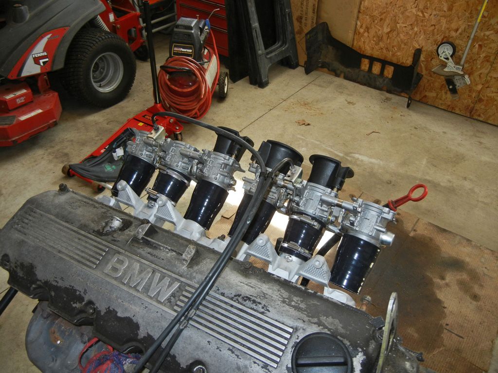
Just to make it look sort of complete I threw the other couplers on and tilted the motor to the angle that it sits in the car. A couple more pics...

Cheers.Last edited by Bullet Ride; 03-12-2013, 12:16 PM.Comment
-
Fantastic work man! This is going to be interesting :) Good luck!Comment
-
Definetly interested in seein the results of this.
Comment
-
Been following this for a good while now. I am doing the same thing for my m30.~ Puch Cafe. ~ Do business? feedback ~ Check out my leather company ~
Instagram: @BWeissLeather
Current cars:
~ '87 325 M30B35 swap
~ '87 535
~ 01 540 Msport 6spd
~ '06 X5 4.8isComment
-
Yeah the weather has finally been decent enough to melt the snow so I can get my car out of storage. I will be taking it out tomorrow and bringing it home. Then I can try test fitting what I've got going on right now.
There should be some updates coming next week hopefully.Comment
-
Props
Props for making your own itbs. I can't when you finish them.Projects Hartge,Alpina & AC Schnitzer Builds.http://www.r3vlimited.com/board/showthread.php?t=280601
http://www.r3vlimited.com/board/showthread.php?t=227993
http://www.r3vlimited.com/board/showthread.php?t=289362
 DSC04926 by Raul Salinas, on Flickr
 DSC03413 by Raul Salinas, on Flickr
Comment
-
Great job! Can't wait to see the finished productComment
-
these gonna be on alpha-N or speed density?
are you going to use an ICV system?89 E30 325is Lachs Silber - currently M20B31, M20B33 in the works, stroked to the hilt...
new build thread http://www.r3vlimited.com/board/showthread.php?t=317505

Comment
-
I'm going to try and stick with speed density since I have the MAP sensor with the megasquirt. I'm hoping that with a vacuum accumulator I won't have any issues with the MAP signal. If I do have issues getting a stable signal then I'll try hybrid alpha-N and if that doesn't work then I'll go to full alpha-N
I'm not planning on keeping the ICV.Comment
-
Dope!! I love the sound of ITB's! Good luck brotha2006 Dodge Magnum SRT8
1986 Slammed Shwarz ETA Coupé (DEAD)
2004 Slammed TSX A/T (Wifey's)
1963 Slammed ChevyII never ending project
1982 Suzuki GS1100GK CaféRacerComment
-
So I brought the car out of storage yesterday. I took it for a rip around the block just to get a little taste before it would be going on blocks for the next few weeks. First order of business was obviously to drain the coolant and pull the intake manifold so that I could test fit my ITBs...


Over all I was relieved to see that everything fit into the car more or less how I predicted it would. The set-up clears the brake booster and will clear the strut brace when it's in place. The only real interference is with the upper heater core hose which I already figured would be an issue.


However after looking at it, it shouldn't be too hard to reroute. If I can find a hose with a tight 90 degree bend I can run the upper line down behind the booster, either that or I'll trim the rib on the tip off of the inlet and solder on a 90 degree copper fitting that I can attach a hose to. Now I just need to figure out the throttle cable set-up as well as what I'm going to do for air filters. The angled velocity stacks are still on the table too.
Happy Easter :)Comment
-
-
Looking great! Put some easter eggs in those stacks to keep the dirt out ;)sigpic
"The bitterness of poor quality remains long after the sweetness of low price is forgotten."
Comment


Comment