
STATUS UPDATE 5/7/2024:
New PCB is up and running on my car, and touchscreen display has been upgraded from 2.8" to 3.5". Get in contact if you'd like one - it's not exactly plug-and-play, but with a little of your own elbow grease should be able to be configured to take data from a huge variety of sources, and both display that data and run control schemes on that data. See this post for more details on the updated hardware, and how I'm using it for my own car. I'll be working on building some decent documentation/how-to guides in the near future, and doing testing to make sure everything works properly with the latest design changes.


STATUS UPDATE 11/4/2023:
New batch of PCBs ordered, with more features. See this post for more details.

ORIGINAL POST:
Hi all,
Want to get a sense of interest in a touchscreen OBC that, among other things, is a pretty feature-rich add-on to a Megasquirt installation, and can give a MS2 some of the features of MS3.
It would have the following features and likely more. This list is mostly what I've already had running for 2+ years in my own car, working pretty flawlessly. Feature set is up to your imagination really:
If you aren't running Megasquirt, you'll still be able to get up to 10 analog sensors connected, and more digital sensors than you'd know what to do with. If your ECU broadcasts CAN data and the protocol used is publicly documented, I can probably get it to work.
Some background:
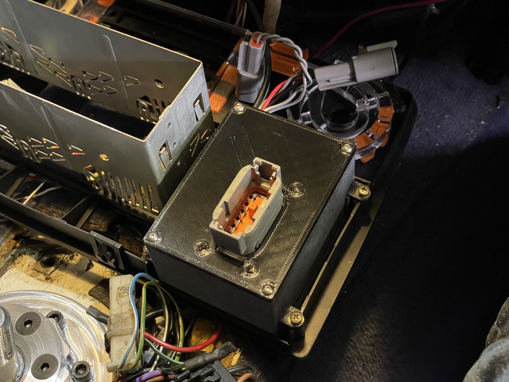
I've touched this list a couple times in the build thread for my VGT turbo project car. The version in my car now is very much a prototype, and I'm already working on a custom PCB design to replicate the setup, maybe with a few extra bells and whistles. Part of this redesign will be to use a TE Connectivity/Deutsch ECU-style enclosure with 2 12-pin DTM connectors for wiring to the rest of the car, with the ability to mount anywhere in the dash/glovebox area (or anywhere else it would fit). Only the touchscreen module would live in the stock OBC location, and it only needs 4 wires to connect to the Deutsch enclosure. Main reason for this change is that I already have a 12-pin bulkhead connector, a 3-pin connector, and a 2-pin connector coming out of the enclosure and I still want to add a few more sensors. 2 12-pin DTM connectors are probably too big for the OBC envelope, not to mention that it's a pain to make any modifications since the climate control panel needs to come out.
It looks like I can only buy these PCB-mounted bulkhead connectors in moderate quantities right now, which is a significant cost, and I only want one for myself. If there's any interest in these, I can come up with a price once I finalize the design. Should be much less than most other digital dash displays, in any case, and integrates nicely. Also no reason you couldn't upgrade to a larger screen in another location (up to 10" is available).
Status and Teaser:
I'm going to continue to do the design work on the PCB and will update the this thread with progress. In the meantime, a few pictures and an awful video of the current setup. Keep in mind the new OBC enclosure would be smaller and be wired to the remote-ish Deutsch enclosure that would be the real brains of the unit:
 Dash display by Mikey Antonakakis, on Flickr
 Untitled by Mikey Antonakakis, on Flickr
 E30 touchscreen OBC by Mikey Antonakakis, on Flickr
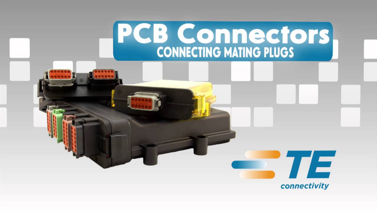
And here's a video on the line of enclosures/connectors I'm interested in:
New PCB is up and running on my car, and touchscreen display has been upgraded from 2.8" to 3.5". Get in contact if you'd like one - it's not exactly plug-and-play, but with a little of your own elbow grease should be able to be configured to take data from a huge variety of sources, and both display that data and run control schemes on that data. See this post for more details on the updated hardware, and how I'm using it for my own car. I'll be working on building some decent documentation/how-to guides in the near future, and doing testing to make sure everything works properly with the latest design changes.
STATUS UPDATE 11/4/2023:
New batch of PCBs ordered, with more features. See this post for more details.
ORIGINAL POST:
Hi all,
Want to get a sense of interest in a touchscreen OBC that, among other things, is a pretty feature-rich add-on to a Megasquirt installation, and can give a MS2 some of the features of MS3.
It would have the following features and likely more. This list is mostly what I've already had running for 2+ years in my own car, working pretty flawlessly. Feature set is up to your imagination really:
- read data from add-on analog sensors such as oil/fuel pressure, fuel pressure, etc.
- read data from more complicated sensors such as turbo shaft speed, accelerometers, etc.
- make your econometer work properly with Megasquirt and bigger injectors
- read CAN broadcast data from Megasquirt
- send sensor data back to Megasquirt for datalogging
- control relays
- control boost solenoids, using Megasquirt (for example, run dome pressure control on Megasquirt 2)
- interface with other CAN devices
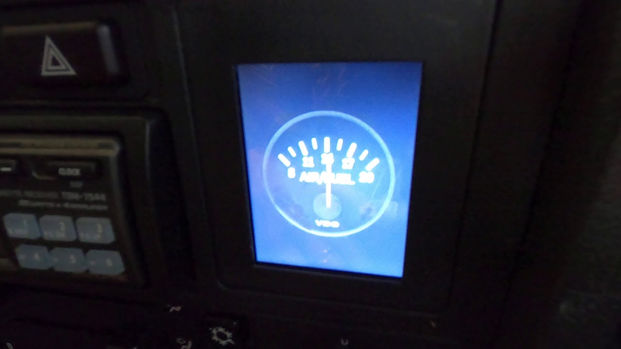
- stock OBC simulation with functional touchscreen buttons (working digital time and date)
- OBC buttons take you to simulated analog gauges
- recreation of e30 analog clock
- fully customizable display if you'd like digital gauges or bar graphs or anything
If you aren't running Megasquirt, you'll still be able to get up to 10 analog sensors connected, and more digital sensors than you'd know what to do with. If your ECU broadcasts CAN data and the protocol used is publicly documented, I can probably get it to work.
Some background:
I've touched this list a couple times in the build thread for my VGT turbo project car. The version in my car now is very much a prototype, and I'm already working on a custom PCB design to replicate the setup, maybe with a few extra bells and whistles. Part of this redesign will be to use a TE Connectivity/Deutsch ECU-style enclosure with 2 12-pin DTM connectors for wiring to the rest of the car, with the ability to mount anywhere in the dash/glovebox area (or anywhere else it would fit). Only the touchscreen module would live in the stock OBC location, and it only needs 4 wires to connect to the Deutsch enclosure. Main reason for this change is that I already have a 12-pin bulkhead connector, a 3-pin connector, and a 2-pin connector coming out of the enclosure and I still want to add a few more sensors. 2 12-pin DTM connectors are probably too big for the OBC envelope, not to mention that it's a pain to make any modifications since the climate control panel needs to come out.
It looks like I can only buy these PCB-mounted bulkhead connectors in moderate quantities right now, which is a significant cost, and I only want one for myself. If there's any interest in these, I can come up with a price once I finalize the design. Should be much less than most other digital dash displays, in any case, and integrates nicely. Also no reason you couldn't upgrade to a larger screen in another location (up to 10" is available).
Status and Teaser:
I'm going to continue to do the design work on the PCB and will update the this thread with progress. In the meantime, a few pictures and an awful video of the current setup. Keep in mind the new OBC enclosure would be smaller and be wired to the remote-ish Deutsch enclosure that would be the real brains of the unit:
Dash display by Mikey Antonakakis, on FlickrUntitled by Mikey Antonakakis, on FlickrE30 touchscreen OBC by Mikey Antonakakis, on Flickr
And here's a video on the line of enclosures/connectors I'm interested in:


Comment