Announcement

Collapse
No announcement yet.

MS3x and wheel speed?

Collapse
X
 
  • Filter
  • Time
  • Show
Clear All
new posts

    MS3x and wheel speed?

    Hey everyone,

    I am trying to determine the best way to get wheel speed (speedometer) input into my megasquirt primarily so i can have the MS3x show that on a digital gauge. I have been searching, but haven't really found an answer to my questions thus far.

    Where is the factory speedometer getting the wheel speed from? Some places i read said transmission, others have said differential. Any input would be very helpful.

    THanks

    #2
    E30 gets its speedo reading from the differential if I'm not mistaken.

    Comment


      #3
      Awesome, thanks for the feedback. Does anyone know if it is a hall type or VR type sensor?

      Comment


        #4
        I remember looking into this a bit and it seemed like a major pain in the ass to add the stock speed sensor from the diff as an input for MS. I believe it is a hall effect sensor.

        If this is just to drive an external gauge or tablet/cluster, you'd have a much easier time just running an external GPS. That is what I am doing with my tablet cluster. All race dashes (AiM, Racepak, etc.) should have GPS inputs as well.

        RISING EDGE

        Let's drive fast and have fun.

        Comment


          #5
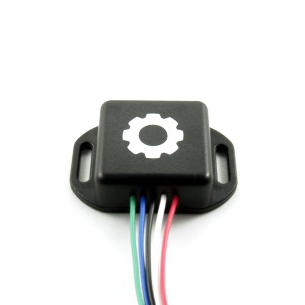
          So i actually found a company that makes a VR to Hall effect adapter.
          Connecting magnetic/VR/inductive sensors and two-wire hall effect sensors to the Cortex EBC will require the use of a speed sensor adapter. These adapters output a 0 – 12 V pulsed speed signal that matches the frequency of the signal produced by a magnetic/VR/inductive sensor or two-wire hall effect sensor.


          It turns the VR signal into a square wave. I ordered one to see how it works. If it is off by a few MPH i honestly don't care that much. I haven't been able to find much info on this aside from one article on a separate forum, but it wasn't very expensive so i thought i would give it a go. I have been communicating with who i assume is the owner, and things look promising so far. If this works well, i would consider using these for the crank and cam sensors as well (depending on accuracy of course).

          Comment


            #6
            What would the benefit of changing the signal be?

            RISING EDGE

            Let's drive fast and have fun.

            Comment


              #7
              From what i have been reading, Megasquirt can accept a hall effect signal for wheel speed. This is essentially what the factory gauge cluster does to the incoming VR signal from the factory sensor and then outputs to things like the cruise control module. From my understanding, people typically connect their MS units to that output on the gauge cluster to get the wheel speed signal. I am not running a factory gauge cluster, so this in theory should convert the VR signal to a square wave that the ECU should be able to understand. This will help with a) display purposes (gauge) and b) pit lane limiter, boost by gear/speed, etc.

              Comment


                #8
                I understand for the speedometer, but why would you alter the cam and crank signals as well?

                RISING EDGE

                Let's drive fast and have fun.

                Comment


                  #9
                  Originally posted by Digitalwave View Post
                  I understand for the speedometer, but why would you alter the cam and crank signals as well?
                  I have heard there are some issues with the internal VR conditioning for those circuits on MS and some people reporting sync issues at either low RPM or high RPM. I woud think this could fix that issue.

                  Comment


                    #10
                    Why are you making it so complicated?

                    Just run the VSS signal from the stock C101 connector or instrument cluster to your Megasquirt. It's already converted from the diff signal, you don't need to do anything other than enter the number of pulses per mile (it's a 9 tooth signal, so you'll have to figure that out based on your tire size).

                    FWIW, it's not a VR or a hall signal. it's actually a reed switch.

                    I have never had any issues with the VR conditioners of any of my megasquirts, and I've been running them for more than 10 years BTW...
                    Build thread

                    Bimmerlabs

                    Comment


                      #11
                      Originally posted by haaken675 View Post
                      I have heard there are some issues with the internal VR conditioning for those circuits on MS and some people reporting sync issues at either low RPM or high RPM. I woud think this could fix that issue.
                      Don't base your decisions on anecdotal evidence. VR sensors work perfectly fine on MS.

                      You can probably put any sensor in that diff sensor hole with a bit of thought.

                      Comment


                        #12
                        Originally posted by nando View Post
                        Why are you making it so complicated?

                        Just run the VSS signal from the stock C101 connector or instrument cluster to your Megasquirt. It's already converted from the diff signal, you don't need to do anything other than enter the number of pulses per mile (it's a 9 tooth signal, so you'll have to figure that out based on your tire size).

                        FWIW, it's not a VR or a hall signal. it's actually a reed switch.

                        I have never had any issues with the VR conditioners of any of my megasquirts, and I've been running them for more than 10 years BTW...
                        I'm not running a factory gauge cluster as stated. From what I have seen there isn't any input capable of turning a VR signal into a speedometer. If you have seen instructions somewhere for this, feel free to send them my way, I would love to see them.

                        I'm not running MS on any standard application, not using an MSpnp, and I am not using factory instrumentation.

                        Comment


                          #13
                          So lets take a few steps back. Have you determined what the differential sensor actually is? if it is a read switch as suggested. youll need a way of converting this into a pulse. See if you can figure out how the standard ecu does this, does it give it 12V and the dash cluster gets a 12v pulse from the read switch?

                          Then you need to look into what the MS3 accepts as a signal. the MS3 appears to have VSS1 and VSS2 in order. One of these seems to be called "launch in".

                          here is a thread where i understand they are saying the 0-12V signal from the diff sensor can be put stright into the launch in input. which i assume is VSS1 or VSS2.


                          if it were me id get stuck into the ms3 documentation and see if launch in will accept this diff sensor 0-12v pulse.

                          now if this all doesn't work. you can get a hall effect sensor and put it on a tab on your tail shaft. if you are only using it for speed this will be fine. but if you want to use it for traction control then you may want like a toothed wheel on the tailshaft.

                          For the time its taken me to write this post i could have done all of this for you, but hey, not my car.

                          Comment


                            #14
                            My suggestion is to use the original circuit from the speedometer to condition the circuit. It is simple and effective. I have the datasheet somewhere, you could easily isolate it and build your own conditioner circuot for pennies.

                            Its not a VR sensor as I stated. The stock circuit makes the most sense IMO since its already engineered and costs nothing. Just the signal proccessing chip (harvested from a stock cluster) and a resistor to calibrate the signal.
                            Build thread

                            Bimmerlabs

                            Comment


                              #15
                              Just looking what Nando said about it being a switch and the ETM block diagram it looks like it's just a simple pulldown circuit based pulse counter in the cluster since one wire from the speedometer sensor goes to ground (within the cluster) and the other to ??? (that info isn't in the ETM). MS3X should be able to handle that out of the box, +5V on one wire to the sensor, the other going to the speedometer sensor input. Might not though, the signal could very messy and conditioned and debounced by the circuitry in the cluster. I'd ask the cluster restoration guy about it and see if I could get a salvaged board or circuit diagram from him and either use the salvaged board or replicate its circuit. Either way it does not appear to be a VR sensor so that module would not help.
                              Last edited by varg; 09-21-2018, 07:00 AM.

                              IG @turbovarg
                              '91 318is, M20 turbo
                              [CoTM: 4-18]
                              '94 525iT slicktop, M50B30 + S362SX-E, 600WHP DD or bust
                              - updated 1-26

                              Comment

                              Working...
                              X