Announcement

Collapse
No announcement yet.

M42 ECU Conversion: Link G4X / E36X

Collapse
X
 
  • Filter
  • Time
  • Show
Clear All
new posts

    #76
    Originally posted by Northern View Post
    So I've been looking at the E36X stuff and I'm wondering how your experience has been so far?

    They say in the spec sheet you linked that, "a G4X PlugIn ECU is capable of the following features if the supports them."
    Incomplete sentence aside, they don't seem to elaborate on this in the E36X document, and have some questionable terms in there (talking about an AFM and how half the pinout descriptions aren't populated - Yes, it's a PNP ECU, but you think the information would be worth putting there for troubleshooting to save even one phone call for support.)

    I'm looking at the feature list for the XtremeX and I'm wondering if any of that is disabled (or completely omitted) on the E36X?
    Stuff like:
    DBW, it mentions an external controller? So does that mean it needs their $300 DBW module? (or could you use the ICV I/O for DBW?)
    "Injector Drives 7 and 8 aren't exposed and don't have the hardware required to drive Injectors." Can you still use these for other outputs? (I don't see them on the pinout)
    Exactly how much of the XtremeX I/O exists?

    I'm not really asking for you to do my research, more so taking the scenic route to the question of: Have you experienced any surprises wrt the above while digging around in it?
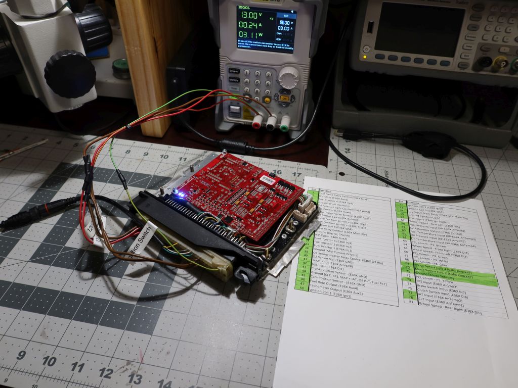
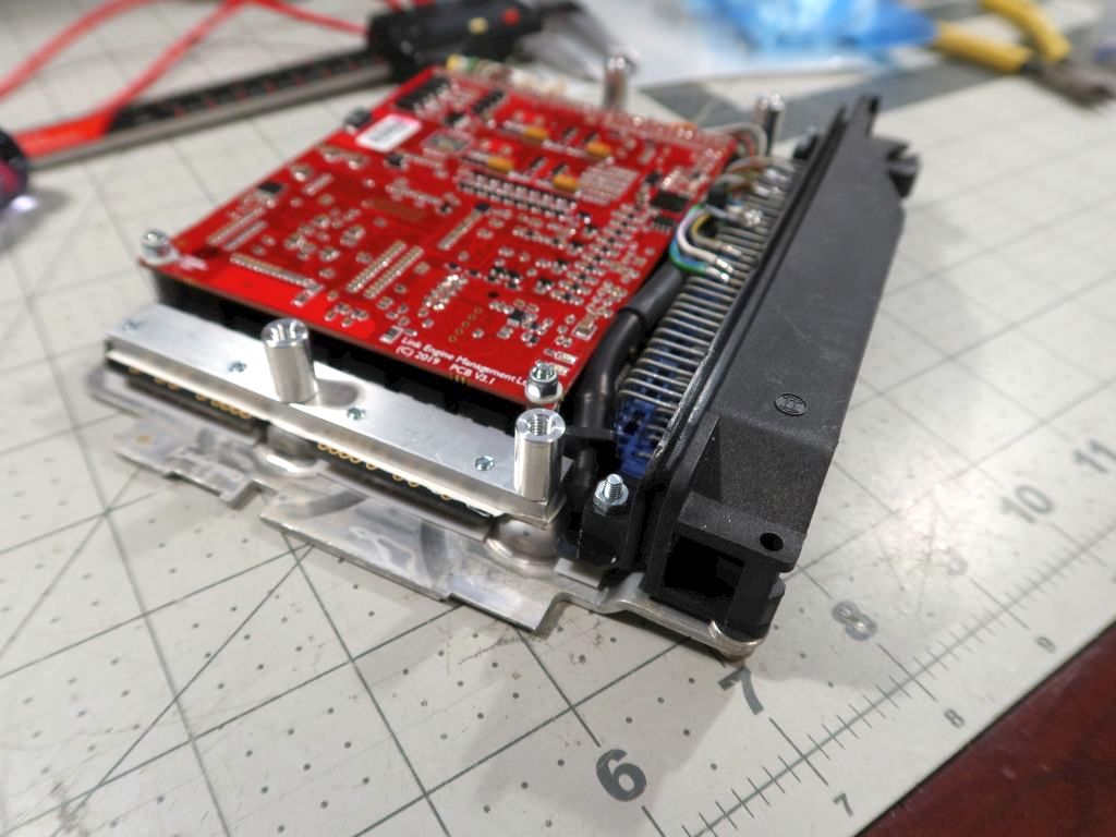
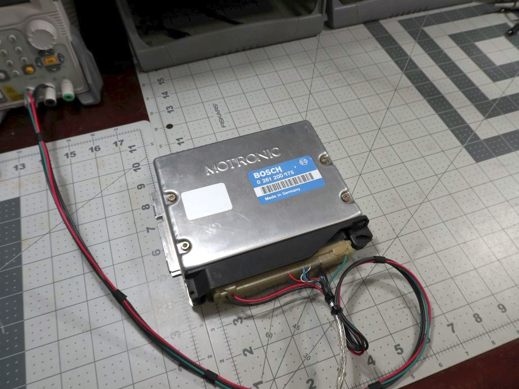
    These are mostly all things that I have asked Link, actually. They have been very good about answering. Basically, it is an almost fully featured G4X XtremeX, except it is missing the last 2 injector drive FETs, and the high-side driver IC since those are pretty rare to need in an OEM setup. What it does have which the regular one does not are onboard MAP and 6 high-current ignition drive transistors which can fire "dumb" coils directly.

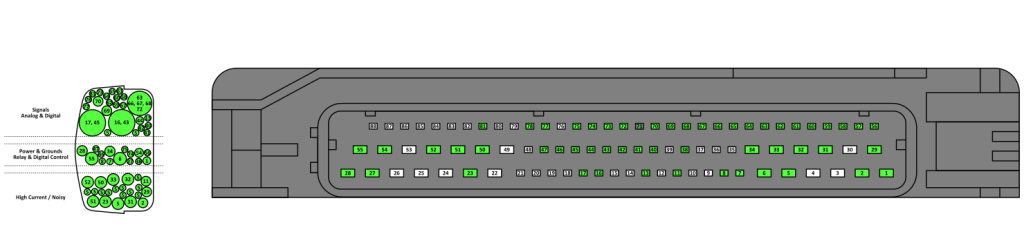
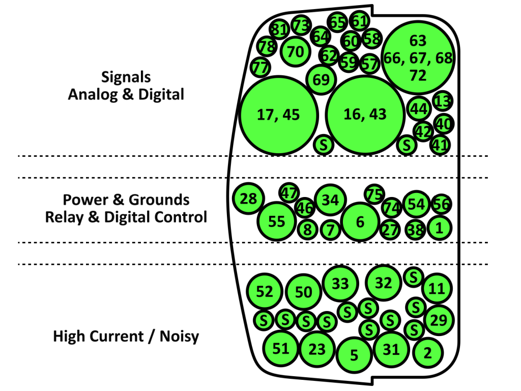
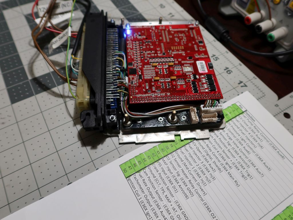
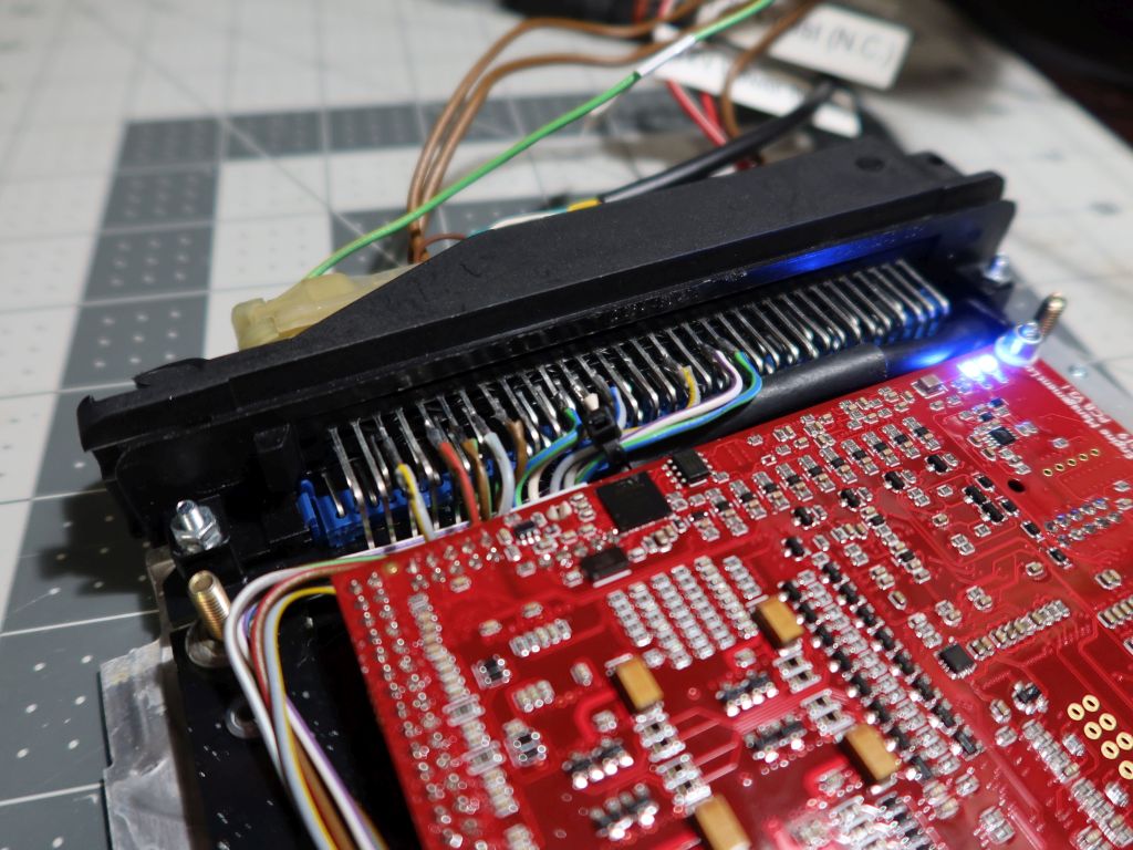
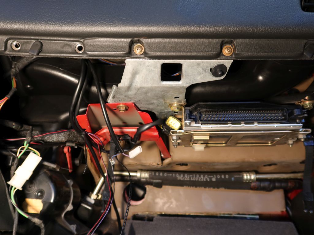
    Now, it is the case that quite a few things are not broken-out to the 88 pin DME connector, but they are all accessible in internal expansion connector and the through hole board-to-board connector that couples the G4X mainboard to the Motronic adapter/daughter board. In my case, I do not think that I will need to actually solder to any of those since there are just enough unused aux inputs and outputs by virtue of me not using this in an E36. DBW would require me to tap into some of them for sure (or give up traction control and fuel+oil pressure), but other than that the required hardware is all in there.

    Here's my Q&A thread at Link where I ask about some of this stuff.
    https://forums.linkecu.com/topic/130...e-application/

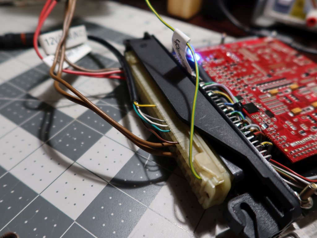
    Their rationale for NOT breaking-out all of the additional inputs and outputs is that it would make a support nightmare with everyone implementing the E36X differently, when it is supposed to be a PnP system. I actually entirely understand that, and don't really have a beef with it. It would not be too hard to figure out what is what on the B2B header inside using a multimeter and the PCLink software, and Link might even just tell you which pins to use if you asked (I doubt they would give you a full map).
    Last edited by bmwman91; 03-19-2021, 10:06 AM.

    Transaction Feedback: LINK

    Comment


      #77
      Long time no update...

      I am still not 100% back to working on this since I have told myself that I will finally deal with the full repaint this fall, but in the interim I have a little time to poke at the ECU project and do some basic legwork. As such, I finally planned out the wire arrangement for the main run that goes from the ECU to the firewall. It always irked me that the factory harness had some wires sort of twisted around one another, and there was a lot of "extra" wire here and there due to how mass production works with these things (harnesses are built out of sub-harnesses in most cases). Well, this sucker is a "too much time on my hands" special one-off, so none of that needed to be left in my new and improved one!

      Now that I am 99% sure of the final ECU pinout, I was able to build a map for the ECU connector entry. Things will be getting a little tight in there, so there can't be any unnecessary crossing or layering of wires as they come in. The general idea is to separate wires by "type", and to have them stacked in a closest-to-farthest-terminal way which will be most space-efficient. I am not about to go crimping terminals on and putting them into the housing yet since I want to do that in the actual car, but it is also the case that I wanted to have the wire runs through the large sheath be approximately stacked in the proper order.

      I built a little wire layout map based on the connection types and positions. All of the high and mid-current stuff is shielded, with the "S" wires being the shield taps that will be joined outside of the connector housing. Knock, crank and cam sensor wires are also shielded.


      If anyone wants the vector art template for a mostly-properly-scaled 88 pin connector (Motronic side) and the mating connector entry opening, it is here:


      So, I put together another basic pin board and got things labelled, sorted and arranged with an absolute minimum of twisting and crossing.


      I am also going to re-design some of the sensor adapters and stuff. The previous ideas were nice and fancy looking, but too much hassle to actually make. I can get the job done much more simply. The main thing that I want to change is the oil pressure+temperature sensor position. I had been planning to install it in place of the stock oil pressure switch, which would be fine and could be done with a simple adapter, but the thermistor would be well out of the actual oil flow and probably read 10-20 degrees cool. At this point, I think that I will have a little mount boss TIG'ed onto the upper portion where the filter element is. Yeah, it is on the dirty side and if somehow the filter got clogged it would not indicate loss of pressure on the clean side (although the housing has an emergency bypass valve), but I don't plan to forget to change the oil or filter for 100,000 miles lol. An additional benefit of having the sensor up there is that I can use the Bosch Motorsport knock sensors since there will be room for the front one again without the oil sensor down in the way. The stock M42 ones are fine, but I would prefer to not deal with sensors that have integrated wires and which might go out of production at some point.
      Last edited by bmwman91; 10-17-2021, 02:44 PM.

      Transaction Feedback: LINK

      Comment


        #78
        Small updates. Since the last post I started a new job, and I have been pretty focused on that as well as some badly needed home renovations. However, this project has not been forgotten, and I am going to start plugging away at it again when I have some time here and there. Basically, I need to deal with some of the custom machined parts for sensor adaptation, and I need to remove the existing wire harness from the engine so that I can properly size everything with the new harness dry-fitted. The harness is about as complete as it can get while not being installed in the car. Luckily, the M42 harness is easy to swap around, and the only headache is removal of the intake manifold (95% sure I cannot just shimmy the wiring box out from under it). I think that I can probably swap in this work-in-progress harness and get everything at the ECU connector side adjusted to the exact right length, and then put back the stock harness in a single weekend.

        This weekend I worked on a couple of things.

        Item 1 was finalizing my strategy for dealing with the shielded cables, specifically in how I will terminate the shields. I had posted some ideas about this earlier in the thread, but I looked back over the NASA workmanship guidelines for harnesses and saw a better solution than trying to terminate things at the end near the connector terminals. The ignition coils' switched primary lines in particular demand care in this area since they see ~425V spikes each time a coil fires, and I do not want any arcing due to damaged insulation or pokey-bits near the terminals.

        Here is a little pile of "experiments" I got some practice with.


        The "aha" moment I had was when I decided that it made a LOT more sense to lash the termination wire onto the shield braid a lot further from the end of the cable. It has a couple of benefits. One is that it doesn't put any risk of a stiff soldered mess of shielding right where the wire will have a sharp bend for the terminal to install in the carrier. The other benefit is that I can do this termination a couple of inches outside of the connector housing entirely; things in there are going to be cramped, and not having the extra wires, solder joints and shrink tubing inside the housing makes life a lot more pleasant. Another change is that I will just use 24ga wire for this. Previously I was taking 20ga wire and trimming off all but 4 strands of the conductors in order to make the lashing manageable. 24ga can be used as-is without hacking it up, and since the termination runs will be at MOST 6", probably more like 3", the smaller conductor size won't really matter.


        I also used up several extra terminals to get my crimping game dialed in. I have several generic crimp tools for this category of terminals, but none of them are specific to TE Timer-series terminals. I really wish I could use the ratcheting ones since they are a lot easier on my hands, but none of them deal with the cable grip portion properly. They all drive the wings straight into the cable and tear up the insulation. So, that leaves me with some non-ratcheting ones which can do the grip & conductor sections separately. The crimps produced by them are, in my opinion, as good as they are going to get without the VERY expensive TE-brand crimp tools (sorry, not gonna drop $1600 for the tool bodies & dies to be able to do MT1, JPT & SPT terminals). I inspected all of them under my microscope and they look like they will be more than adequate to ensure good electrical contact & a clean hold on the insulation.


        Item 2 for the weekend was implementing the little customizations on the E36X ECU itself. I want all connections made through the 88 pin connector. It doesn't really matter for any practical reason, but I like the simplicity of having a single point of connection. It would be trickier if I was using the built-in MAP sensor since there's no way to run a vacuum line through the factory connector, but since I am installing a MAP sensor directly into the intake manifold all I need is wires. With all of the sensors I am adding to the engine, I needed to use all of the extra analog & digital lines on the internal expansion connector. None of those connector terminals were internally routed to the 88 pin connector, so I made a little mini harness and soldered the wires directly to several unused pins on the output connector. Also, I want to have the USB interface cable fully integrated into the rest of the harness, so I did some similar hacking to put all of its connections onto unused pins. It works just fine and there are no communication issues with it set up this way. I guess we'll see how it goes when the car is running and the ignition is firing since the ignition leads are going to be right there next to things.


        I am also going to start poking through the PCLink software interface more. There is a LOT of capability here! Since my last post, Link has released about a dozen firmware updates with fixes and features. It is great to see that they support their product so well (it helps that the E36X is based on the G4X which is their current generation product).


        Transaction Feedback: LINK

        Comment


          #79
          Originally posted by bmwman91 View Post
          I really wish I could use the ratcheting ones since they are a lot easier on my hands, but none of them deal with the cable grip portion properly. They all drive the wings straight into the cable and tear up the insulation. So, that leaves me with some non-ratcheting ones which can do the grip & conductor sections separately. The crimps produced by them are, in my opinion, as good as they are going to get without the VERY expensive TE-brand crimp tools (sorry, not gonna drop $1600 for the tool bodies & dies to be able to do MT1, JPT & SPT terminals). I inspected all of them under my microscope and they look like they will be more than adequate to ensure good electrical contact & a clean hold on the insulation.
          Any chance that one of the ratcheting crimper dies could be modified so that it doesn't arc the strain relief tabs so tightly? Basically grinding that section from the sideways "8" shape into a larger radius "O"?

          Surprised there isn't something that exists for the ratcheting crimpers already
          Originally posted by priapism
          My girl don't know shit, but she bakes a mean cupcake.
          Originally posted by shameson
          Usually it's best not to know how much money you have into your e30

          Comment


            #80
            Yeah, the thought to stick the dies on a mill and hog out the little protrusion crossed my mind. Not sure if it is worth it since I am "only" crimping ~120 terminals lol.

            I am sure that there are cheap ratcheting crimpers out there that have the circular profile in the cable grip area, maybe I need to dig around Amazon a bit more.

            Otherwise, I guess I will get some grip strength training!

            Transaction Feedback: LINK

            Comment


              #81
              These look like they would fit my cheapo Princess Auto ratcheting crimpers, but I think some nicer crimpers have their dies attach differently.

              L JPT Quick Change Crimper Die for Female Junior Power Timer Terminals. 927776, 929929, 929930, 929938, 929931, 929940, 929942


              Shipping from Aus not ideal, but they look right to me.
              Originally posted by priapism
              My girl don't know shit, but she bakes a mean cupcake.
              Originally posted by shameson
              Usually it's best not to know how much money you have into your e30

              Comment


                #82
                Interesting. I have come across some Chinese crimpers that have "L" and "L1" dies which say they are for JPT and MCP terminals. The company also has dies for SPT (Standard Power Timer).


                Unfortunately I cannot find anywhere that actually sells their tools lol.

                It looks like there is a kit on eBay, and it is not terribly expensive.
                Die Material: AISI- 4140. Precision and Wax-lost Casting. Where to Use: Electrical connector common throughout the auto industry can be found on: Mass air flow sensor (MAF), pressure sensor (MAP), Ignition system, Coolant Temperature sensor (CTS), Oxygen sensor, Clutch pressure connector and EV1 injector etc.


                I had a coworker check out my crimps today. He used to be a trainer for IPC, focused on terminal crimps and wire harnesses. Basically the crimps are fine, despite not being passable if they were coming from a factory or if they were intended for use on a robotic arm or something where the conductors are subject to wide ranges of motion & torsion. For use on a car, things looked perfectly fine since there is a little vibration and heat, but nothing really wild otherwise. The bigger thing is paying attention to routing & making service loops, which is not an issue since the OEM pigtails are already fine in that regard, and I had planned out the same considerations for the new stuff. So, I think I will keep working with the crimpers that I have since I already spent the money and they do a fine job. A tired hand is the main downside!
                Last edited by bmwman91; 06-29-2022, 10:08 PM.

                Transaction Feedback: LINK

                Comment


                  #83
                  Oh, also I pulled the intake manifold and got the stock harness out of the car this evening. I'll rough in the new harness tomorrow and start trimming things to length. The main item will be to pull the wires in/out of the cabin as needed so that they are the ideal length when the terminals are installed in the 88-position ECU connector housing. Most of them can be trimmed to the final length in the engine bay that way. It does appear that many of the stock wires will be "too long" since I made some optimizations in how they are routed / not tangled, so I may end up chopping the original terminals off to get them the right length at the ECU. Even on the stock harness that I just removed, the main loom in the glove box is about 1.5" too long since I had completely taken that harness apart, cleaned it, modified it for my WBO2 & MAF sensors. To deal with it I had to form a big "kink" in it next to the ECU, and I want to not have that little feature in the new one!

                  Last night I crimped all of the JPT and MT1 terminals onto the wire ends, and prepped the shielded cables as needed. So, I think that tomorrow I should be able to get them all plugged in to the main connector. It'll be mated to the stock ECU, with the big back shell pulled further up the main loom, so I can plug wires into the terminal carrier with it in its actual position.

                  Transaction Feedback: LINK

                  Comment


                    #84
                    Progress report from a few evenings this past week.

                    Also, I updated the diagrams in post Track & AutoX to reflect the current design that I am working on.


                    I finalized how I want to have the ends of the shields lay. Things I wanted to avoid were having sharp cut ends in a position where they could dig into the inner conductor's insulation (mostly for the ignition coil lines since those see ~450V spikes), and I wanted to have the termination taps outside of the plug housing (my solution for that was in one of the previous posts). While I realize that this is obsessing over minutia, it is both part of the fun and a little extra insurance against needing to deal with electrical gremlins. Anyway, my solution is to trim the shields down to ~3mm, fold them back over the outer sheath, and then apply some Raychem DR shrink tubing over it all.


                    The final result.


                    Next up was to install the work-in-progress into the chassis to start sizing and trimming.


                    I did not like how the factory power wires were routed in the original setup, so I used a little bit of heat gun action to soften the insulation and re-route the main power taps for a cleaner arrangement. I think I have seen these routed like 3 different ways on stock E30s, so maybe some cars had this better arrangement depending on who the assembly tech was that day lol.


                    At the main wiring box...LOTS of new wires! Some old ones. Zero original connector housings other than the crank and cam position sensor receptacles (which I cleaned up and reapplied heat shrink tubing to). The stock connector housings were heat-staked so that you cannot extract the terminals without making a bit of a mess of things, so I just lopped all of them off back when I was taking the donor harness apart for cleaning and tidying. Most of the pigtails in the main wiring box had a ton of extra wire, crimps and rubber boot covers due to how the harness was assembled. I assume it is a mix of improved efficiency from doing the housing assembly + heat staking at some remote assembly station and then just crimping them into the main loom, and probably also to have "extra" wire in there in the event that the pigtails get damaged so that there's more to work with during a repair.

                    Whatever the case, I replaced almost all of the original wires with new Tefzel ones in single, continuous lengths. I will be adding a few splices to some of the wires which go between C101, the diagnostic connector, the alternator, and the starter. The original "lots of extra wire + splices" portions of those are gone, so it'll be cleaner in the end. Due to minimum order quantities for wire, it was not worth it to me to order $50 worth of heavier gauge colored wires to replace these. I'll detail all of that some other time when I work on the wire box itself.


                    The first thing I wanted to do was to get the main connector at the ECU populated, which meant that some stuff in the engine bay had to be in the approximately correct place. While the new runs of wire can be slid in or out as needed, the wires from the relays, C101, and the diagnostic port needed to be cut to the proper length at one end or the other. The terminals at the ECU are the easiest to dal with IMO, so I decided to get things in the engine bay laid in their final configuration, trim the ends near the ECU, and crimp new terminals on.


                    After carefully referencing my schematic and the arrangement in my stock harness, I reassembled the relay blocks. These terminals are of the Standard Power Timer series (same series used in the M42 ignition coil connectors), although the stock ones at the relays are some oddball type I cannot find anywhere which are a lot easier to remove than the type that is commercially available. So, a goal was to not chop any ends off there, and to do so elsewhere as needed. The one exception was the O2 sensor power wire (which will feed my WBO2 controller) since the stock wire was too short to reach where it needed to go and, you know, no splices if they can be avoided lol. So there is one newer style terminal in there, and God help me I hope I never need to remove it!


                    With most of the "harder to adjust" stuff adjusted, I secured the run on the firewall a little more so that it would be in its final location.


                    Once I had the relay blocks done and taped + zip tied their service loops, I was able to get going inside the car at the ECU. It was...a bit of work lol.


                    After a few evenings of work, it was in a mostly-assembled state.


                    A few things remain to be done, and I will do them after I remove this harness from the car since it will be a lot more pleasant on a bench. For one, the big ground splice that joins most of the ECU grounds was cut off since there was entirely too much extra wire there. Also, I need to add a couple of wires to the main ground splice, and it is best done with a new one. Also, the cam and crank sensor cables need trimming. All of the original wires that I kept ended up being 2-6" too long thanks to untangling them & doing a little route optimization. That is with me leaving a fair amount of slack in all of them too lol (none of them are pulled tight, and service loops are present where needed).


                    You can see how excessively long the cables are here. I will trim them down, and the cable shielding will also be a lot closer to the ends this time. As you may be able to see, things are getting a little tight in that connector housing! The other thing I will do off-car is splice into the shields of all of the new (white) shielded cables. The taps will be staggered out over the wires just outside of the connector housing, before the big sheath.


                    So there it is for now. Work is pretty busy right now, so progress will be made here and there. This project is not getting finished any time soon!
                    Last edited by bmwman91; 07-04-2022, 09:26 PM.

                    Transaction Feedback: LINK

                    Comment


                      #85
                      This week's updates:

                      I got the ignition coil cable assembly finished up. It is more or less the same way that I did it on my rebuilt OEM harness, so I had the strategy worked out well from prior experience. The only difference this time is that I wrapped some areas of sheathing in harness tape since I found that in the 2 years since rebuilding the OEM one, there were some small friction marks from where it passed over coil bolts.

                      The crimps came out nicely now that I have a lot more practice lol. Better looking than then ones in the last harness I did! The final setup will have things zip-tied to the coil mounts and stuff, but since I plan to pull the harness out soon I didn't worry about those.


                      Next up was putting a new sheath on the main ground conductors. It was a tight fit over the ring terminal, but some assistance from some brass wire did the trick to pull it all through.


                      After that, I decided to wrap up the last of the stuff on the passenger side and get the WBO2 (Spartan SLC2) connector done. It is a LOT easier to do than in the OEM harness rebuild since in that one, I retained the thick shielded cable. There is no need for that here since the output is an actively-driven 0-5V signal.


                      After that it was time to start looking at the "busy" side with the main wiring box.

                      As those who have followed this thread will recall, I was never really all that happy with how the fancy oil pressure + temperature sensor was fitting in the oil filter housing, and locating it there was making it hard to fit the knock sensors. Well, I recalled that there were some plugs on the back of the head, and I pulled the one with M12x1.5 threads. I was pleasantly surprised to see oil start running out of it. So, I think that this will be a much better place for the sensor. It will give a good read of the pressure at a critical functional location, and I imagine that the temperature will be more representative of things since there is not as much stagnant oil around it. There is about 8mm of space between the rubber boot and firewall pad, so plenty of room there as well.


                      As a bonus, the M12 plug from the head can be reused in the oil filter housing. With the area cleared out, I can use the Bosch Motorsport sensors instead of the OEM M42 ones. There is no functional difference, but now I do not need to worry about the sensors going out of production. The rear knock sensor is a bit of a tight fit and the coolant hose will lay on it a bit, but such is life. As far as I can tell the OEM sensor in the E36 M42 is the same way.


                      Some test-fitting of things for the fuel injector harness got going as well. I am doing away with the OEM setup with the connector in the wire box, and the injector wiring will be part of the main harness now, running directly from up on the firewall. I still need to think a little more about routing & strain relieving, but I think that my general plan here will work. Small holes will be drilled in the bottom of the harness tray so that I can zip tie the sheath to it in a couple of places, and I will look into some rubber grommets for the opening.


                      Since this path has the cable sheath contacting the head, I looked through my bag of extra OEM boots & grommets and found an ugly but functional solution. This will both help to locate the cable, and keep it from getting abraded due to engine vibration. As for where it enters the tray, I need to look around online for generic grommets that might work.


                      I also got the 12V power pigtails started in the "new" wiring tray.


                      The last thing I looked into was the fuel pressure + temperature sensor. My original plan was to machine a fitting that would go into the fuel feed hose a few inches before the rail, but I have never really liked that. It will move around a lot (wire fatigue), and honestly the fewer hose clamps you have on the fuel system the better (fewer potential failure opportunities). Gasoline is nasty stuff, and leaks at 45PSI are a recipe for disaster.

                      Since the intake manifolds are off of the car, I started playing around with the sensor to see if there is anywhere it could fit on the stock rail. There are in fact a few places, and this one is the best I think. If I turn a small steel bung on the lathe and machine a hole in the rail at the spot I marked, the bung could be TIG'ed on for a very clean arrangement. My only concern is that the inside of the rail seems to be powder coated, and the heat from welding would cause it to flake off. The injectors have filter screens, but I do not need clogs. So, I think that some little metal brushes or pipe cleaners could probably be bent and worked around the inside after welding to knock the charred stuff loose. Flushing out the rail is pretty easy, so as long as I can knock any bad paint off, I should be able to get it out.

                      Anyone got thoughts on this approach?


                      Transaction Feedback: LINK

                      Comment


                        #86
                        More progress this week.

                        I got all of the stuff at the wiring box finished up, so for the most part wiring items that are under the hood are complete. It came out looking pretty clean, although a few areas were a royal PITA to get all of the sheathing stuffed into. With all the new wires I have added, it got to be a pretty tight fit through most of the grommets!


                        Even with all of the new wires, the inside of the wiring box is actually cleaner and less cramped than the factory setup.


                        For the knock sensors, I did not want to terminate the shields out at the connector ends since those are subject to some amount of movement and vibration. So, I used some lash splices with ground taps up in the wire box, and ran the ground taps out to the connectors. In the OEM configuration, the shield is the ground connection for the knock sensors, so this is a little modification of that. A bonus is that I can run the shield up even closer to the end.


                        One of the trickier parts was dealing with the injector sub-harness. There is not a lot of space inside of the plastic tray, and I am using wire that is of a heavier gauge and stiffer to bend. Anyway, long story short, it took a bit of time and thought to get everything to fit in there.


                        Remaining items to do:
                        - Wrap wire bundles with harness tape
                        - Make ground taps on all 13 shielded cables just outside of the main ECU connector
                        - Connect the ground taps to stuff
                        - Trim & terminate the cam & crank sensor wires at the ECU
                        - Install the 6 wires needed for the 4 wheel ABS sensors, brake switch, and clutch switch
                        - Need to find a suitable, small 6-position connector set to make the above item easy to disconnect
                        - Install the QuadVR conditioner module near the ABS unit
                        - Install the PCLink cable into the ECU connector
                        - Make modifications to the upper intake manifold to adapt the TMAP sensor
                        - Make necessary modifications to the stock fuel rail to adapt the PST-F1 sensor
                        - TUNE!

                        Transaction Feedback: LINK

                        Comment


                          #87
                          Things have been busy with work and family the last couple of weeks, but I have made progress here and there. I finally got around to uploading some pictures and posting here.

                          The harness is 100% complete now. All assembly is done, and everything is 100% tested point-to-point to make sure that all wires go to the right places. At the main ECU connector, things are pretty packed! I can still add a few more wires in the future if needed/desired (such as a CAN bus to additional sensors & loggers), but it is otherwise quite full.


                          It took a little work and thought to get all of the ground taps installed nicely, but I am very happy with how they all turned out.


                          I had a bunch of rubber caps left from the sacrificial harnesses that I took apart over the years, so all of the parallel splices got nice OEM coverings. Also, I got the cam and crank position wires trimmed and installed, with the shielded portion of the cables running up MUCH closer to the wires' termination than in the OEM setup. Granted, noise on the VR sensor lines never seemed to be an issue to begin with, but I want to minimize any possibility of false triggering from ignition noise.


                          Once I was certain that everything was right, I put it back into the car and taped up the main umbilical which goes to the ECU. There are several tight turns that all of the wires have to make to get from the firewall to the ECU, and I wanted all conductors to be laying in a neutral way before taping them down into a bundle.


                          The rest of the taping up on the firewall was done on a bench since zip ties could hold everything in place while I removed the harness from the car. Trying to tape the firewall sections on the car would be a big pain.


                          Next up was dealing with the 4 channel VR sensor conditioner which will take the 4 ABS wheel speed sensors and turn their output into something usable by the ECU. To start, I extracted the necessary wires from the ABS computer plug, chopped off the original terminals (at the factory crimps), and installed new terminals with my wires combined with the originals. For reference, the ABS computer connector uses Junior Power Timer (JPT) terminals. The ones in there originally are an older style but the new ones fit fine. They are very easy to extract, too.


                          Here's the conditioner board all wired up and ready for the enclosure to be added.


                          And here it is tucked up into the knee bolster area.


                          The last thing to deal with was the connections to the brake and clutch switches. With the brake switch, I could have ordered some right-angle 2.5mm circular terminals, but I got impatient and just cut the original wire and used a parallel splice. Even the Mona Lisa has its imperfections lol. As for the clutch switch, since the E30 318iS never had cruise control, no existing wiring or anything was present. Luckily, the clutch switch, connector housing, and mounting bracket are still available and not too expensive, so it was easy to get set up.


                          Here is the other end of the sub-harness I made for the wheel speed sensors and pedal switches (ends at the yellow thing). If I ever have to swap back to the OEM harness and ECU, I do not want to have to snake this stuff back out of the dashboard, so I put a connector on it to allow disconnection from the new main harness. It tucks up nicely next to the ECU housing.


                          And of course, one of my trusty little helpers was providing moral support while I sweated and cursed in the driver's footwell. Her "help" is a mixed blessing...there is a lot of cat fur that needs to be vacuumed out of the car lol.


                          I just need to do some minor machining work to make the fuel sensor adapter, and to modify the upper intake manifold to take the TMAP sensor. I tried milling the fuel sensor adapter, and quickly found that I hate stainless steel. I bought 303 since it is considered a "highly machinable" grade of stainless, and it just ate up a HSS cuter. So, I shudder to think about what the "less machinable" alloys are like! Anyway, I just need to go pick up some basic carbide cutters (square end mill & 90° chamfering cutter) for the adapter. Hopefully I can knock that out in the next couple of weeks.

                          Transaction Feedback: LINK

                          Comment


                            #88
                            I had a little fun this evening and got some of my woodworking tools going for a little bit. To machine the top of the intake manifold to accept the TMAP sensor, I need a way to mount it to the mill's bed. The mounting flange is 40.3° from horizontal (design was probably 40°, but sand casting tolerances are usually not all that great), so I shaped a scrap of very dry, fairly dense Doug Fir 4x4 into a mounting jig. I do not expect the cutter loads to be very high since the manifold is aluminum and I will be using a 1/2" or smaller end mill to take a few light passes. So, I will just screw the manifold right onto this, bolt it down, and go for it!


                            Being that it is almost autumn, I am getting the itch for building speakers or furniture. It's been a year or so since my last woodworking project, and for whatever reason I always seem to start projects right about now. But, I am allowing myself one project at a time, so I guess it's extra motivation to get the car done!

                            Transaction Feedback: LINK

                            Comment


                              #89
                              Small updates since this was a busy week. I got a little time on the lathe and made some small parts.

                              One thing I wanted was some little spacers for securing the top Motronic lid. The stock ECU has internal heat sinks for the various power transistors and stuff, but the E36X does not. Anyway, I just made some little threaded spacers and it all worked nicely. No loose Motronic lids here!


                              The other little bits that I turned out were some bushings for the TMAP sensor. I will shrink fit these into some counterbores I make in the top of the intake plenum, and probably stake them for a little extra security (or maybe a dab of JB Weld under the flange). The plenum is ~3mm thick, which is not great for securing the sensor with an M6x1 screw, nor will it allow the o-ring to seal. These little bushings take care of that for me. Next I just need to find some time to actually mount and modify the intake manifold.


                              Transaction Feedback: LINK

                              Comment


                                #90
                                Small update. I had lots of momentum going on this, and then got busier with work and stuff. This weekend I managed to get a few hours in to work on the last of the machined parts, namely the adapter for the fuel sensor. Let's just say that I really do not like stainless steel much when it comes to machining it!

                                I made some small tweaks to the adapter to make it easier to cut. It is going to be made with a combination of operations on a mill and lathe. Over the weekend I started out pretty well, and the got stuck after burning up some drill bits. For the main milling operations, I had obtained some carbide cutters on eBay (1/2 the cost of McMaster, and while the quality is likely not the same, I am not running hardened stainless and only making one of these), and those did great. I wouldn't say that they cut it like butter, but there was no BS involved. Most of the holes were also bored without event, despite only having some TiN coated HSS drill bits on hand.

                                However, I got hung up with the hole for the sensor. As anyone who has worked with SS knows, it work hardens pretty easily if you mess up, so it is very unforgiving with HSS cutters. So, the pilot hole went fine, and I moved on to drill it out larger (one size smaller than the finished diameter). What I suspect happened is that that second bit had a chipped flute that I did not notice. So, I started trying to drill with it, and it just work hardened the part. You know you messed up when your hole starts emitting light lol. Anyway, it is not hard to deal with, but I need to drop another bit of cash on a 9mm carbide end mill on eBay. If I had caught the chipped HSS drill bit, I probably would have been fine, but alas I did not. Live and learn. Carbide will take care of this.

                                The "simplified adapter". Truly simple would be if I just left it as a block, but things are tight down where I want this thing so I want to reduce its size, and it is just sort of fun to make it look nicer.


                                The part came out looking reasonably good for a DIY experiment, between the proper cutting tools and a little rouge cloth on a surfacing block.


                                You can see the nastiness where drill bits went to die. It will be easy enough to fix/finish. I also started the M10x1 tap in here, just to make sure that cutting the threads was not going to fail completely. Thankfully the tap felt pretty good for the ~5mm or so that I was able to run it before it hit the lip where the drill bit died.


                                The hole and counterbores for where the fuel feed tube will be welded in came out really nice. Apparently HSS drill bits can work on 303SS if they are not damaged.


                                Transaction Feedback: LINK

                                Comment

                                Working...
                                X